
|
|
Forum Index : Microcontroller and PC projects : LCD + Pico combo
| Author | Message | ||||
| MikeO Senior Member Joined: 11/09/2011 Location: AustraliaPosts: 275 |
Milled version of the board has been loaded with components, initial testing found a couple if problems. The circuit pin outs for the linear reg is not correct, the Vout and Gnd are swapped. I jury rigged the regulator and to continue testing. All good except there is no electrical connection between the 3.3v and pin 3v3 on the PicoMite. I made a wire link on the board which energised all the 3.3v supplies on the PCB. So all is looking good, I will do testing with he Pico and the display tomorrow. Mike .jpg) .jpg) .jpg) Codenquilts |
||||
| Mixtel90 Guru Joined: 05/10/2019 Location: United KingdomPosts: 8989 |
The 3.3v regulator is only for the ESP module. Nothing else uses it so if you aren't using that it can be omitted, together with the capacitors. Mick Zilog Inside! nascom.info for Nascom & Gemini Preliminary MMBasic docs & my PCB designs |
||||
| lizby Guru Joined: 17/05/2016 Location: United StatesPosts: 3837 |
So further to that, as designed, the components other than the ESP will only have 3V3 if the Pico is plugged in and its usb port is also plugged in. PicoMite, Armmite F4, SensorKits, MMBasic Hardware, Games, etc. on FOTS |
||||
| Mixtel90 Guru Joined: 05/10/2019 Location: United KingdomPosts: 8989 |
Correct. The ESP can draw up to 400mA on startup and 300mA over a slightly longer time, settling down to about 80mA depending on mode. That might be a bit much for the 3v3 output from the PicoMite, so I used a 500mA LDO to get a second 3v3 supply from the 5v rail. I could probably have used a smaller one but the LF33 is cheap enough. LF33 Regulator Having the supply contact quite close means that (if you aren't using the ESP), with a couple of links you can ground 3V3EN to turn off the SMPS and link to the linear reg's output to the 3V3 rail to get a quiet supply. The LF33 is wired correctly on the PCB design, although an early drawing shows it with the tab on the left. It should be on the right. In-Gnd-Out when looking from the "front" of the reg. The outermost rail on the pcb is +5 and the next one in is Gnd. Edited 2021-07-29 02:35 by Mixtel90 Mick Zilog Inside! nascom.info for Nascom & Gemini Preliminary MMBasic docs & my PCB designs |
||||
| MikeO Senior Member Joined: 11/09/2011 Location: AustraliaPosts: 275 |
Oh,thanks for putting me right everyone, I had spent so much time in the isolation milling exercise and (obviously) no where near enough on the subtleties of the Raspberry Pico design! Also unfortunately the LD33v low dropout I had in stock I had ASSumed to be a similar device, wrong, different pin out. Bad Day.. Mike Codenquilts |
||||
| lizby Guru Joined: 17/05/2016 Location: United StatesPosts: 3837 |
And thanks very much for your guidance about that. Now bookmarked. Question: is milling the surface of the bed the best way to get a bed at a perfect right angle to the milling bit? What's the best material for the bed? What's the best surface planing bit? PicoMite, Armmite F4, SensorKits, MMBasic Hardware, Games, etc. on FOTS |
||||
| Mixtel90 Guru Joined: 05/10/2019 Location: United KingdomPosts: 8989 |
Apart from the minor reg mishap (easily done - I wish they were all the same!) that build is looking very nice, Mike. Congratulations on being the first (known) builder. :) I'm glad it seems to be working so far - my "posh" PCBs should be leaving China today and I might get sad if there are any major problems. lol Mick Zilog Inside! nascom.info for Nascom & Gemini Preliminary MMBasic docs & my PCB designs |
||||
| MikeO Senior Member Joined: 11/09/2011 Location: AustraliaPosts: 275 |
Milling a "base" board that you can reliably place back onto your mill's deck is the best way to go to ensure a parallel surface. My mill has less than 0.3mm variance over 200mm X and Y axis but that can be significant when you are trying to mill 0.08mm(3mil) into a 1oz copper pcb blank. Even then it is very preferable that you are also able to apply a "warp" or leveling factor to your gcode as even when you are running parallel the pcb blanks are not flat and can be distorted easily depending on how you mount them to the milling surface. I think double sided tape is probably best. Baseboard material , I settled on some marine (good quality) ply-board for my latest jig, as it strong and mills well without "feathering" which can happen if you use MDF/HDF. Just mill sufficiently into the baseboard to deal with any slope. then you can stick your "spoil" board to that area. You could also use HDPE (High Density Polyelyethylene) , kitchen cutting boards are a good source, cheaply. Surfacing bit, bit depends on your Mills capabilities and chuck/collet size , I now use a cheap 13mm router bit . It has a 1/4" shaft but it mounts ok "tightly" in a ER11 6mm collet. This help a lot when you want to surface 200mm square area. Do a roughing dept then a final fine cut to finish off. Good luck Mike Codenquilts |
||||
| lizby Guru Joined: 17/05/2016 Location: United StatesPosts: 3837 |
Thanks very much, Mike. My device hasn't arrived yet, so I'm taking notes. PicoMite, Armmite F4, SensorKits, MMBasic Hardware, Games, etc. on FOTS |
||||
TassyJim Guru Joined: 07/08/2011 Location: AustraliaPosts: 6554 |
You might want to have a look at autoleveler. http://www.autoleveller.co.uk/ It measures the uneven nature of a PCB then modifies you gcode to give accurate depth of cut. Handy if you use cheap PCB blanks. Jim VK7JH MMedit |
||||
| Mixtel90 Guru Joined: 05/10/2019 Location: United KingdomPosts: 8989 |
PCBs have arrived! 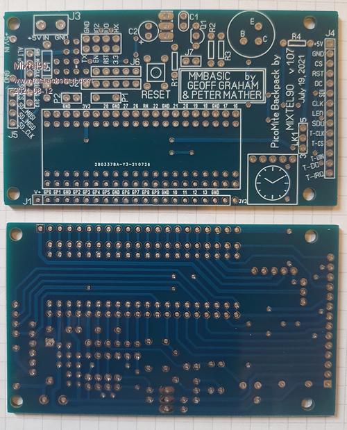 I'll populate one soon and give it a test. Probably when the British Standard Weather (i.e. rain) returns. Mick Zilog Inside! nascom.info for Nascom & Gemini Preliminary MMBasic docs & my PCB designs |
||||
| lizby Guru Joined: 17/05/2016 Location: United StatesPosts: 3837 |
Looking good. Can you provide OPTIONS? PicoMite, Armmite F4, SensorKits, MMBasic Hardware, Games, etc. on FOTS |
||||
| Mixtel90 Guru Joined: 05/10/2019 Location: United KingdomPosts: 8989 |
I can do better than that. :) PicoMite Backpack.zip Mick Zilog Inside! nascom.info for Nascom & Gemini Preliminary MMBasic docs & my PCB designs |
||||
| lizby Guru Joined: 17/05/2016 Location: United StatesPosts: 3837 |
Nice, thank you. I used 47R for R4. Learned the hard way that if the RTC is mounted on the same side as the Pico, then it needs to be oriented so that the silk-screen clock is visible, not covered. Scratch one hot RTC module. I had a lot of trouble with GUI CALIBRATE, but finally got it to work. SD card module used, not the LCD socket on my smaller ILI9341, though I could probably have made it work with long-pin headers. option list OPTION SDCARD GP22 OPTION SYSTEM SPI GP18,GP19,GP16 OPTION SYSTEM I2C GP12,GP13 OPTION LCDPANEL ILI9341, LANDSCAPE,GP20,GP21,GP17 OPTION RTC AUTO ENABLED OPTION GUI CONTROLS 59 OPTION MEMORY 60160, 100608 OPTION TOUCH GP14,GP15 GUI CALIBRATE 0, 4305, 0, -1425, 9223372036854775807 > rtc settime 2021,8,12,11,37,1 > ?date$,time$ 12-08-2021 11:37:15 > PicoMite MMBasic Version 5.07.00b11 Copyright 2011-2021 Geoff Graham Copyright 2016-2021 Peter Mather > ?date$,time$ 12-08-2021 11:47:27 > files A:/ 1408 bench.bas 35819 db_list.bas 640 grain.bas 1536 menu.bas 896 sieve.bas 512 speed.bas 4608 ta.bas 4736 tain.txt 47000936 tajunk.txt 936 taout.txt 313 us-500.def 107000 us-500.tbl 15029 us-500_City.ndx 299 us-500_County.ndx 12023 us-500_Last_Name.ndx 3897 us-500_State.ndx 7013 us-500_ZIP.ndx 0 directories, 17 files Thanks to Mixtel90 & VegiPete for this sweet design. $4.55USD from JLCPCB for 5 boards, slow boat shipping with PayPal payment. PicoMite, Armmite F4, SensorKits, MMBasic Hardware, Games, etc. on FOTS |
||||
| Mixtel90 Guru Joined: 05/10/2019 Location: United KingdomPosts: 8989 |
Thanks, lizby. :) I'll make a note about the RTC in the doc for the board. I'll own up - I messed up at the design stage. I tried all sorts of ways to get the RTC onboard. I've got a board running now too. Yep, I had fun calibrating the display too but it works eventually. GUI CALIBRATE 0, 3897, 3757, -897, -673 LCDPANEL option RL puts the SD card at the top & USB socket on the RHS. The distance between the display and backpack is intended to be 11mm as that's a standard length for metal spacers. It will depend on the connectors used though and sometimes 12mm spacers might be better. Now I could do with a RTC module that was actually calibrated! This one isn't very good and I haven't got a big posh frequency counter to set it up. :( I wonder how accurate the CMM2 is? Hmmm.... Edit: The SD card socket on the display works fine if the 2.8" display is used. Edited 2021-08-13 02:32 by Mixtel90 Mick Zilog Inside! nascom.info for Nascom & Gemini Preliminary MMBasic docs & my PCB designs |
||||
| Mixtel90 Guru Joined: 05/10/2019 Location: United KingdomPosts: 8989 |
New release of the doc for the MicroMite Backpack 1.07. PicoMite Backpack.zip Now has photos, construction section with BOM, much better cad drawings for the board & circuit diagram and a few more tweaks. Mick Zilog Inside! nascom.info for Nascom & Gemini Preliminary MMBasic docs & my PCB designs |
||||
| thwill Guru Joined: 16/09/2019 Location: United KingdomPosts: 4380 |
Thanks Mick, I hopefully have all the necessary parts on order (or in stock) with the exception of: 1. Can someone point me at an appropriate 1A schottky diode on eBay or aliexpress ? 2. Will a 2N3906 do for the PNP transistor or do I need something capable of handling more mA ? Best wishes, Tom MMBasic for Linux, Game*Mite, CMM2 Welcome Tape, Creaky old text adventures |
||||
| Mixtel90 Guru Joined: 05/10/2019 Location: United KingdomPosts: 8989 |
1N5817 or 1N5818 should be fine if you see those. The diode is only used if you are powering the board from the 5V terminals, not the USB input. Check your display before bothering about Q2. If it's version 1.2 or later you may not need it as the LED input pin is via a 1k resistor to an on-board transistor. The LED pin can go straight to a PicoMite pin. Edited 2021-08-14 00:31 by Mixtel90 Mick Zilog Inside! nascom.info for Nascom & Gemini Preliminary MMBasic docs & my PCB designs |
||||
| thwill Guru Joined: 16/09/2019 Location: United KingdomPosts: 4380 |
OK, I'm not entirely certain what I'm doing yet so I'll order a couple to have them on hand. Remember that when it comes to electronics I'm strictly "monkey see, monkey do" (monkey get wrong, monkey get frustrated, monkey start hollering and throwing poo). The board I "inherited" from Lewis is a v1.1, hopefully the one I ordered from Aliexpress will be a later version. Best wishes, Tom MMBasic for Linux, Game*Mite, CMM2 Welcome Tape, Creaky old text adventures |
||||
| Volhout Guru Joined: 05/03/2018 Location: NetherlandsPosts: 6006 |
If you know how to adjust the rtc you have, best to adjust it is using a locked gps 1hz output as reference and align to that. If your rtc has a 32 khz output simply count 1 1hz period a d adjust to 32768. That gets you within 30ppm. Then adjust for 327680 in 10 seconds. 3ppm. That is about as good as you can get it. PicomiteVGA PETSCII ROBOTS |
||||
| The Back Shed's forum code is written, and hosted, in Australia. | © JAQ Software 2026 |
