
|
|
Forum Index : Microcontroller and PC projects : *** COMM *** Mick�s PCB offerings
| Author | Message | ||||
bigmik Guru Joined: 20/06/2011 Location: AustraliaPosts: 2981 |
GDay Rob, All, The YELLOW is really quite impressive considering that the RED & GREEN LEDs are on and off alternately, ie RED is On when GREEN is off and vice versa. I know there are RGB versions of the matrix modules but I think Curtis would have a heart attack if I asked him (actually I did) to try to get it to work.. it would mean 3 x MAX7219 chips and I doubt I could fit them onto the PCB, 2 was hard enough.. But I am also sure that the limitations of BASIC might make that task a bit too much to ask anyway. Regards, Mick Mick's uMite Stuff can be found >>> HERE (Kindly hosted by Dontronics) <<< |
||||
| Justplayin Guru Joined: 31/01/2014 Location: United StatesPosts: 330 |
 RGB! Nope, not happening! I'm not going to do it! RGB! Nope, not happening! I'm not going to do it!
Okay, maybe next week. 
But seriously, I don't think MMBASIC can handle it and I'm sure I can't. --Curtis I am not a Mad Scientist... It makes me happy inventing new ways to take over the world!! |
||||
donmck Guru Joined: 09/06/2011 Location: AustraliaPosts: 1314 |
Recently I was given a Mik-Matrix by Big Mick. The hardware of the unit was put together by Mick and the software was written by Curtis Pratt. In the 1980s, I produced a similar LED moving message board, initially mono, then later tri-colour. This was featured over 4 consecutive issues in Silicon Chip when they had just started their magazine. I used a Z80 micro and wrote all of the software in machine language. A big task in those days. When I saw the Mik-Matrix unit, it brought back memories of the enjoyable time I spent programming my devices. I had space invader characters, jumping crocodiles, ringing telephones, etc. But the amount of hardware was much more expensive and much more involved than the maximite "Basic Program" unit with nice LED drivers, that the lads have come up with. My only criticism is that doing it all in "Basic" is stretching the timing capabilities of the micro, and a nice C Driver needs to be written to top it off. Mick showed me two versions of the LED displays. One version would almost burn your eyeballs in daylight conditions. :-) I imagine these little displays could be used as a lapel name badge, or a message board in the back window of a car, either to warn the driver behind you to back off a little, or even as an enhancement to turn indicators and stop lamps. Documentation can be seen at http://www.dontronics.com/micks-mites/files/index.php?dir=11+Mik-Matrix%2F Cheers Don... https://www.dontronics.com |
||||
| Justplayin Guru Joined: 31/01/2014 Location: United StatesPosts: 330 |
Mick, Received the packet of Mites yesterday. I knew the NanoMites were small, but I was still shocked when I physically had one in my hand! It is smaller than my thumbnail! You are a master of miniaturization. Which explains how you were able to squeeze Mik-Matrix together to hide behind the LED module. --Curtis I am not a Mad Scientist... It makes me happy inventing new ways to take over the world!! |
||||
| bigmik Guru Joined: 20/06/2011 Location: AustraliaPosts: 2981 |
Hi Curtis, All, Hardly a master of miniaturisation, I think kiiid probably will take that one but then all tracking for the NanoMite was done on a 0.006" clearance and track widths and was at the limits of Shenzhen2U's design criteria.. (in fact I breached that on the `shorting' pads which are at 0.004" gaps, but they worked out OK) and the tracks were routed by hand not auto-routed.. As to the Mik-Matrix, I really was surprised at how hard it actually was to get all of the tracking done, for a while there I had 2 nets that would not fit, I was about to start pushing the track widths & gaps on it but I wanted to stick to 0.010" for each of these (5V and GND are thicker) but I finally got them routed through.. There was no room to move as I wanted the PCB to be the same size as the LED modules so the modules could butt up together. Regards, Mick Mick's uMite Stuff can be found >>> HERE (Kindly hosted by Dontronics) <<< |
||||
| cicciocb Regular Member Joined: 29/04/2014 Location: FrancePosts: 74 |
Hi Don and Mick, you should have a look at this dotmatrix display on ebay . It' a little bit difficult to deal with it but I think it could be interesting for you. I already assembled one and interfaced with a pic32 and the result are not so bad; it could be brighter but it's very cheap! I'm waiting for more units in order to make a larger display. Regards, CiccioCB |
||||
lew247 Guru Joined: 23/12/2015 Location: United KingdomPosts: 1709 |
None of the links are working here (I'm in the UK) The main site dontronics.com works fine |
||||
| WhiteWizzard Guru Joined: 05/04/2013 Location: United KingdomPosts: 2991 |
@cicciocb Are the Matrix modules common Anode or common Cathode?? Thanks, WW EDIT: Just noticed the schematic and they look like common Anode!  |
||||
| donmck Guru Joined: 09/06/2011 Location: AustraliaPosts: 1314 |
Had to have a laugh at the description: It is DIY kit. User need to weld it. Cheers Don... https://www.dontronics.com |
||||
| donmck Guru Joined: 09/06/2011 Location: AustraliaPosts: 1314 |
Mick asked me to change the location of the files. missed it by a 's' Location is in his signature now: http://www.dontronics.com/micks-mite/files/ Cheers Don... https://www.dontronics.com |
||||
| cicciocb Regular Member Joined: 29/04/2014 Location: FrancePosts: 74 |
Hi, I confirm that are common anode. I confirm also that It is DIY kit. User need to weld it. 
CiccioCB |
||||
| bigmik Guru Joined: 20/06/2011 Location: AustraliaPosts: 2981 |
Hi cicciocb, lew247, all, Yes, I have looked at those displays, there is an RGB unit similar I have been looking at. The problem is that I reckon it needs CFunction to get it to work, I can barely navigate basic let alone C.. It is because of the proliferation of modules like these that the common anode modules are so cheap but YES they are very dim, no doubt try to keep costs down to be competitive. @lew, Sorry we had an issue with a 'free' counter (that shows how many visits my pages had) that decided that because it was free it could spit all manner of SPAM and SCAM pop ups. Due to Internet and browser cache the only way to fully kill it was to change the URL which seems to have fixed the problem.. The new URL is in my signature at the bottom of all of my messages... Sorry that I neglected to update this thread with the new details. Regards, Mick Mick's uMite Stuff can be found >>> HERE (Kindly hosted by Dontronics) <<< |
||||
| bigmik Guru Joined: 20/06/2011 Location: AustraliaPosts: 2981 |
@Don, Yes WELD the unit, I have a welder here, should I use the 20Amp or 40Amp setting? What diameter rods should I use to do the job..????


Mik Mick's uMite Stuff can be found >>> HERE (Kindly hosted by Dontronics) <<< |
||||
CircuitGizmos Guru Joined: 08/09/2011 Location: United StatesPosts: 1427 |
Rods? What a thug! This is fine electronics. You would use a wire feed MIG...
"The problem is that I reckon it needs CFunction to get it to work, I can barely navigate basic let alone C.. " Actually it uses SPI, so it is completely accessible with MMBasic. Micromites and Maximites! - Beginning Maximite |
||||
| cicciocb Regular Member Joined: 29/04/2014 Location: FrancePosts: 74 |
Hi, if you want I can help you to make the program in C. I already interfaced it with a pic32 so, if you want, I can send you the code. Regards, CiccioCB |
||||
| bigmik Guru Joined: 20/06/2011 Location: AustraliaPosts: 2981 |
Hi All, I am pleased to blatantly advertise a new board! The Serial BackPack 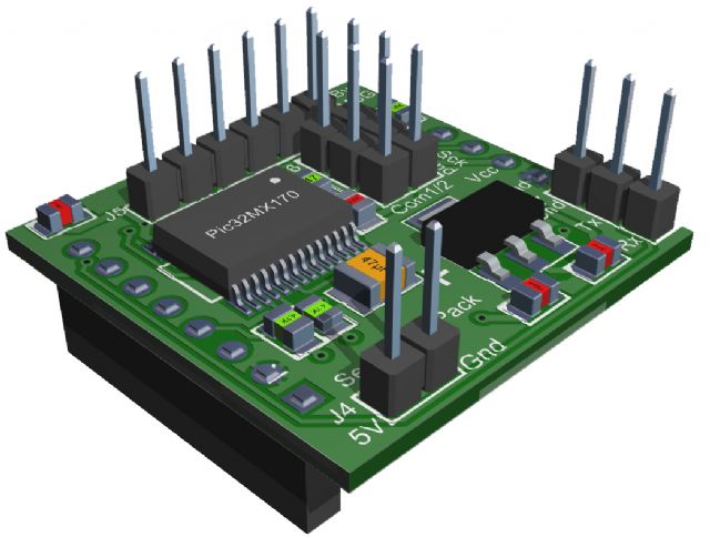
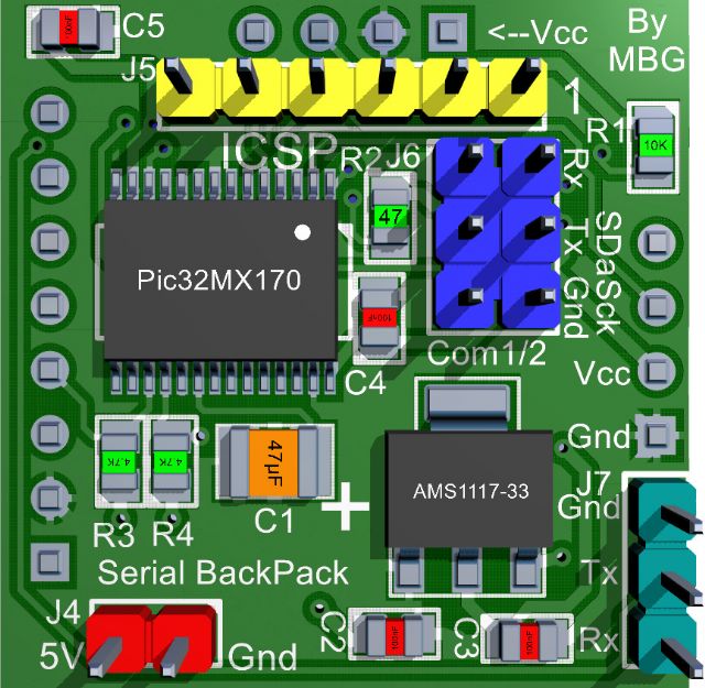
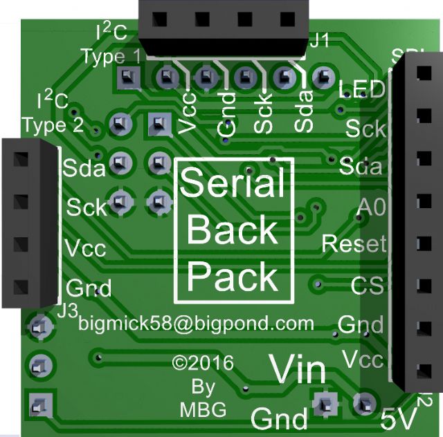
This is a BackPack board for the I2C based 1306 OLED 0.96" displays (supports 2 different pinouts) and also supports the small, SPI 8pin TFT modules and NOKIA 5110 (although there are 2 pinouts for the NOKIA module it only supports one type) The PCB is approx 28mm x 28mm square and has a PICMX170 SSOP uMite onboard. It is designed primarilly to accept commands via serial (com1 or com2) or the Console (all ports provided for via male headers). Of course it could run stand alone if you wish, although there are limited IO lines available. I have priced the boards as below: Serial BackPack --------------- Option 1 Bare Board only ................................................. $2AUD Option 1a 3x Bare Board only ............................................. $4AUD Option 1b 6x Bare Board only ............................................. $7AUD Option 1c 9x Bare Board only ............................................. $10AUD 1 x PIC32MX170 50MHz SSOP (Not programmed) ............................... $8AUD 1 set SMD's (1xAMS1117-33,4x100nf, 1x47uF, 1x10kohm 2x4k7ohm, 1x47R) ..... $2.50AUD/set All details including manual can be found on my `Site' There is a 5MB video clip showing it driving an OLED display and receiving commands from one of my MuPs in the link above that will show what it is designed to do. Note! the clip shows it connected via a male/female header, it does look silly as the board and display are so small, I recommend after you are happy with your development directly soldering the Serial BackPack to the relevant display module. Special Thanks goes to Peter Mather for the original C based driver and John Gerrard for poking me with a hot stick in the eye until I agreed to do the design for him, as Serial BackPack has come about as a direct result of his request. Thanks also to John (JMAN) for allowing me to include his demonstration files on my `site' and to distribute with this board. Kind Regards, Mick Mick's uMite Stuff can be found >>> HERE (Kindly hosted by Dontronics) <<< |
||||
| drkl Senior Member Joined: 18/10/2015 Location: HungaryPosts: 102 |
Hi Mick, Cool!!! Best regards drkl |
||||
| JohnS Guru Joined: 18/11/2011 Location: United KingdomPosts: 4355 |
Maybe worth adding the board's dimensions to one or more of the JPGs? The overlay maybe? John |
||||
| bigmik Guru Joined: 20/06/2011 Location: AustraliaPosts: 2981 |
Hi John, I have mentioned the board is 28mm x 28mm (1.10") but I have to admit it doesn't register how small they are until you see them. I designed it to be the exact size of the 0.96" OLED modules but with the panelising it has added 0.5mm or so. It comes out as approx. 28mm square.. I sent one to Iliya (of Autotrax DEX fame) and he was shocked at its size because he has been using my pictures (above) in his demonstrations on the DEX forum and didnt realise its size. It is so small it looks outright silly connecting to the display with male/female headers, see the Video clip Sample.MP4, on the link above.. You may have to download it to view it.. With my NanoMite (15mm square) I took a picture with a 5c coin and I reckon not one person realised how absolutely small they were until they had them in front of them. Here it is with a few AUSTRALIAN coins for comparison. 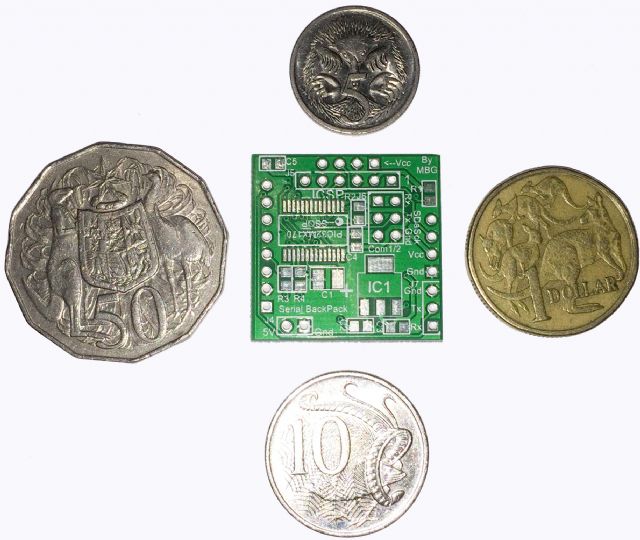
Kind Regards, Mick Mick's uMite Stuff can be found >>> HERE (Kindly hosted by Dontronics) <<< |
||||
TassyJim Guru Joined: 07/08/2011 Location: AustraliaPosts: 6549 |
Showing off your wealth again Mick. Jim VK7JH MMedit |
||||
| The Back Shed's forum code is written, and hosted, in Australia. | © JAQ Software 2026 |
