
|
|
Forum Index : Microcontroller and PC projects : *** COMM *** Mick�s PCB offerings
| Author | Message | ||||
| WhiteWizzard Guru Joined: 05/04/2013 Location: United KingdomPosts: 2794 |
Hi Mick, I have just finished building one of these - what a fantastic, and very useful little module at a very low price bearing in mind it uses a GENUINE FTDI part. My only comment would be that I would have extended the 3v3 output from the chip to the 6-way header (possibly onto Pin 4 which is currently No-Connection). Even though it has limited drive capability - it is useful for testing MicroMite modules that have no onboard 3v3 vReg. In a way I'm glad you didn't do this as it means there is still a market for my module - so no need to 'add' this feature just yet! 
Thanks for yet another useful BigMick product 
WW For everything Micromite visit micromite.org Direct Email: whitewizzard@micromite.o |
||||
bigmik Guru Joined: 20/06/2011 Location: AustraliaPosts: 2870 |
Hi Phil, Thanks for your comments, I didn't run 3v3 out to the J2 header for two reasons. First, there is only 50mA drive from the FTDI chip and its own 3v3 IO and I didn't think that would leave enough overhead to drive a uMite unless there was either minimal other peripherals or it was clocked down. and Secondly, I designed it to fit onto a MuP and Mup has its own 3v3 Regulator on board and feeds 3v3 OUT on the pin 4 in question. Also that leaves the 3v3 market open to yourself for your nice little board.
Regards, Mick Mick's uMite Stuff can be found >>> HERE (Kindly hosted by Dontronics) <<< |
||||
| bigmik Guru Joined: 20/06/2011 Location: AustraliaPosts: 2870 |
Hi All, There is a new/updated manual now available! Thanks Don! Here is the updated manual for MuP-TTL Mik Mick's uMite Stuff can be found >>> HERE (Kindly hosted by Dontronics) <<< |
||||
| bigmik Guru Joined: 20/06/2011 Location: AustraliaPosts: 2870 |
Hi All, I am pleased to announce that I now have available the SMD-BP170 which is the big brother (but same physical size) to the BackPack170 Top 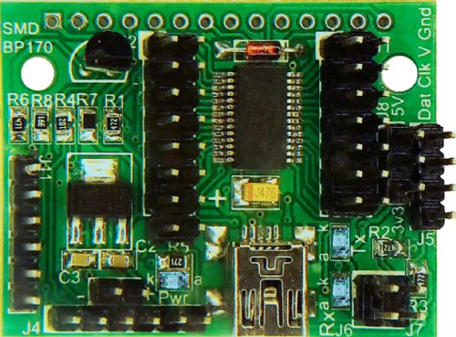
Bottom 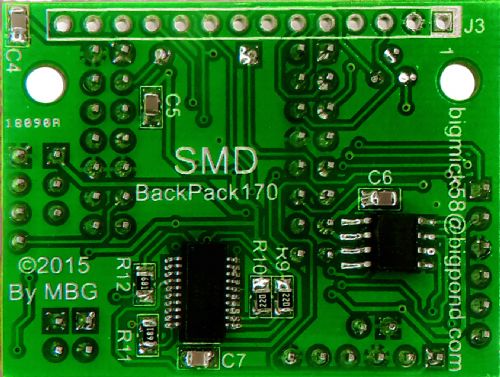
SMD-BP170, as its name suggests is a Surface mount (mostly) version of the BackPack170 and like its predecessor is designed to mount onto the back of a 2.4" or 2.8" SPI TFT Touch screen.. Due to the fact I have used a lot of SMD components in this design I have been able to keep the size to 43.5mm x 32.5mm (1.71� x 1.28�) and incorporate the same functionality as BackPack170 and add the following features: ICSP Programming header FT231X USB-Serial bridge (and USB connector) A DS3232MZ High accuracy real time clock chip (spec'd as �0.432 Second/Day) The Manual can be found HERE I have priced the SMD-BP170 as follows: Option 1 Bare Board only ................................................ $3AUD Option 1a 3x Bare Board only ............................................. $7AUD Option 1b 6x Bare Board only ............................................. $12AUD Option 2 Bare Board plus SMD Voltage Reg and SMD 47uF cap ............... $5AUD Option 3 Basic kit (No DS3232MZ or FT231X) .............................. $16 Option 4 Medium kit (No DS3232MZ) ....................................... $20 Option 5 Full kit (includes. DS3232MZ and FT231X) ....................... $32 Related parts, if purchased separately. Pic32MX170 28pin SSOP (Not programmed).................................... $8AUD FT231X 20pin SSOP ........................................................ $5AUD DS3232MZ 8pin SSOP ....................................................... $12AUD NOTE! That at this stage I cannot program the SSOP Pic32MX170 until it is soldered to a built board but I have ordered an SSOP socket that should allow me to program them in future (no extra charge). If anyone is interested please don't hesitate to contact me via PM or email: Regards, Mick Mick's uMite Stuff can be found >>> HERE (Kindly hosted by Dontronics) <<< |
||||
| ajkw Senior Member Joined: 29/06/2011 Location: AustraliaPosts: 290 |
Mick, Thanks for getting my order away promptly, I eagerly await. Cheers, Anthony. |
||||
| paceman Guru Joined: 07/10/2011 Location: AustraliaPosts: 1329 |
Mick, I'll have to take back all the nasty things I've said about Australia Post lately. I PM you yesterday for the new SMD BackPack 170, you send the kit at about 9:00pm and I receive it over here at 2:00pm the next day - brilliant! I guess the others probably don't know we're about 30km apart on opposite sides of the same city (Melbourne) but even so that's a record. I'm amazed you managed to get all that functionality on such a small card and yet still have header access to all the pins - and it fits spot-on between the connector and the SD card on the ILI9341 2.4" & 2.8" TFT displays I've got. Great effort! Greg |
||||
| bigmik Guru Joined: 20/06/2011 Location: AustraliaPosts: 2870 |
Hi Anthony, I hope you get it soon, but don't expect it quite as quick as Greg's.. @Greg, Whooooowww!! I think that is about a record.. Goes close to the 3 1/5 days to Scotland... It was posted about 6pm but maybe the postie picked it up nearer to 9pm.. I am happy to pay extra postage (I will pass it on to my customers anyway ..HeHee) if they deliver like that.. But then I have the one that took 11 days to Newcastle (next state) and the one that took 5 weeks to the US... Go figure. Anyway... Let me know how you go when you build it up. Regards, Mick Mick's uMite Stuff can be found >>> HERE (Kindly hosted by Dontronics) <<< |
||||
| bigmik Guru Joined: 20/06/2011 Location: AustraliaPosts: 2870 |
All, I have just added a small bit in the manual about colour of J9 (Battery backup input for J9) and J12 (INT and 32kHZ RTC out) to make them stand out amongst the black connectors as they are pretty tightly packed. The updated manual can be downloaded from HERE No big deal and not worth printing out a new copy if you have already done so. Regards, Mick Mick's uMite Stuff can be found >>> HERE (Kindly hosted by Dontronics) <<< |
||||
| paceman Guru Joined: 07/10/2011 Location: AustraliaPosts: 1329 |
Mine's up and running now Mick. Had a couple of tiny glitches to sort out - I managed to melt the clear plastic of one of the yellow 0805 LCD so replaced it with a 1206 blue one I had here - fits fine. Also had a bit of messing around getting the driver to load on my Win XP Home system. It couldn't find anything on the web by itself so I went to the link you gave in the Manual, and downloaded the "CDM v2.10.00 WHQL Certified" driver folder and pointed it at that. It loaded it the first time but then said it hadn't loaded properly - and it wasn't showing in the "loaded hardware devices". So I started again and the second time it loaded ccrrectly and fired everything up fine. I've set mine up at the moment with male headers pointing down (as below) so I can access all the headers easily and I've currently mounted it on a small breadboard so I can change the display I'm using easily. As you note though that's not how you'd normally do it in a project - it'd be underneath. It's all very neat - one USB cable only and you're away. Greg 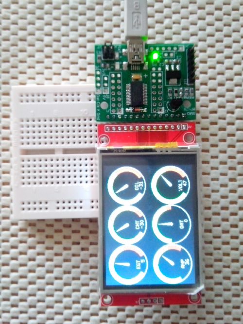
|
||||
| bigmik Guru Joined: 20/06/2011 Location: AustraliaPosts: 2870 |
Hi Greg, I have to laugh, sorry Greg, one of my LEDs was moving all over the shop and got stuck on the tip of my iron at one stage, I found it after a few seconds and it still worked and I gathered they must be glass as nothing melted that shouldn't have... This driver issue is interesting, I have had 3 comments now about either slow install or not installing.. I had no issue with win 8.1 but win 7 needed to be told to load them but then found them automatically online. I can only assume they are slightly different driver configs from the FT232RL chip. That's the whole point, Of course you do not have to attach it to a display it is a pretty neat uMite board in its own right. Anyway thanks for getting back to me with some feedback Greg, Time to have some fun with it now. Regards, Mick PS, I am wondering if there is anyone wanting a 44 pin version of this board or even a 470 version, although that board would probably be bigger and I would put a parallel interface on it as well. Regards, Mick Mick's uMite Stuff can be found >>> HERE (Kindly hosted by Dontronics) <<< |
||||
jman Guru Joined: 12/06/2011 Location: New ZealandPosts: 711 |
That would be most welcome Jman |
||||
| paceman Guru Joined: 07/10/2011 Location: AustraliaPosts: 1329 |
Definitely Mick - I'd like a 470 version too with a header for the 40 pin parallel interface; guess it would have to be the 64 pin variety at this stage. A header for the SD card socket that comes with the TFT screen PCB's would be excellent too - you'd probably need to connect that with a short ribbon cable? Since it would have to be a bit bigger it probably means the PCB will have to extend across the back of the SD socket but that would hardly matter to the "thickness" of the two boards mounted together as long as there was nothing "tall" mounted in that area. The extra area could then be used for other good things.
These would be some of my extra things and changes thoughts: 1. A 16mm "slip under" battery holder for the RTC. 2. An small ON/OFF switch - it's a bit of a nuisance having to unplug the USB cable to turn things off or re-boot. 3. Maybe DIP switches or just solder pads for some of the links to keep the profile low, e.g. the I2C pullups. 4. Make the BC337 SMD instead of TO92 - same reason. 5. Link to allow direct Tx/Rx access to bypass the FTDI chip if it's mounted. 6. Protection to allow 5v feed via the header. I'm sure we could think of more  - love this design by committee! - love this design by committee!
Greg Edit: Oops - hadn't read Mick's new thread - this probably should be there. |
||||
| bigmik Guru Joined: 20/06/2011 Location: AustraliaPosts: 2870 |
Hi Greg, I moved to a new thread to try to keep this one on context... Further discussion will be in this Thread Regards, Mick Mick's uMite Stuff can be found >>> HERE (Kindly hosted by Dontronics) <<< |
||||
| ajkw Senior Member Joined: 29/06/2011 Location: AustraliaPosts: 290 |
RE SMD BP170 Thanks Mick, my fully optioned kit arrived earlier this week and is now up and running. No trouble with the FTDI 'drivers' with Linux, just plug it in and away you go. Some trouble with the construction however, after 'completing' the build and programming the firmware I couldn't get it to work, I had missed installing the big C1 after doing all those small little blighter's. At first the small 0805 components seem impossible but once you get into it they are not hard to solder at all. So thanks again for a great board, excellent service and a well put together & fun kit. Now for some coding. Cheers, Anthony. |
||||
| bigmik Guru Joined: 20/06/2011 Location: AustraliaPosts: 2870 |
Hi Anthony, Yes the missing VCap might just be a little problem there.... Glad you have everything working as expected.. Regards, Mick Ps the 0805 parts aren't that difficult to solder once you get used to them. Mik Mick's uMite Stuff can be found >>> HERE (Kindly hosted by Dontronics) <<< |
||||
| MMAndy Regular Member Joined: 16/07/2015 Location: United StatesPosts: 91 |
Do have a "MuP-Test" for the up-coming MM+ Explore 64 stamp module? If you decide to design one ... Since you can put the headers "up" or "down" on this module then your module will need a accommodate this change. Also, due to a larger GPIO, why not go with SMT resistors and LEDs to save cost and PCB board space? |
||||
| bigmik Guru Joined: 20/06/2011 Location: AustraliaPosts: 2870 |
Hi MMAndy, Whilst I really like this idea I have to admit that MuP-Test has NOT been a very popular board.. For the life of me I don't know why. I invested about $100 in Leds and Resistor packs etc thinking this would be a must-have and be a big seller, but I think I `may' have just about broken even 14 months after I released MuP-Test. If I did do a 470 based I would first see what platform it `stabilised' in. Whilst the `stick' is a reasonably good developing platform it may not end up as the preferred board. I am working on a 470 based BackPack board that supports the Parallel and SPI displays (40pin and 14pin) that If It works out I would consider a test board for it.. I think, given the SMD style chip, a Led Test board would/should be more popular as there is more likely hood of a soldering problem to the chip. Regards, Mick Mick's uMite Stuff can be found >>> HERE (Kindly hosted by Dontronics) <<< |
||||
| bigmik Guru Joined: 20/06/2011 Location: AustraliaPosts: 2870 |
Hi All, 
Introducing Mik-Matrix , a moving LED Message display. This is a joint project between myself and Curtis Pratt, as such, boards may be obtained from either of us.. I am located in Australia and Curtis is in The United States. This project has been a while in the making and I have to say that I can't stop smiling when I look at the message I have constantly scrolling on top of my PC. Curtis has done a fantastic job with the software side of things and has implemented the following features. RED text, GREEN text, YELLOW text, MIXED text (colours alternate with each character) STRIPED text (colours alternate with each vertical column) FLASHING text (with any of the above colours) Flash Speed adjustment Scroll rate adjustment Brightness adjustment 18B20 support for Temperature readings RTC Support Curtis has also catered for several functions, such as Christmas and New Years Day count down timers. Full details including the hardware Manual and Software Manual can be located here. Mik-Matrix Documentation I have priced the PCBs etc as follows: Option 1 Bare Board only ................................................ $2AUD Option 1a 3x Bare Board only ............................................. $4AUD Option 1b 6x Bare Board only ............................................. $7AUD Chinese (slight external blemish) Low Brightness 8x8 BiColour LED Matrix $5AUD each 1 set R's and C's (2 x 100nf, 2 x 10uF, 2 x 10kOhm) SMD .................. $1AUD/set The Chinese Bi-Colour modules, whilst cheaper than the Sparkfun modules, are much lower insensity than the Sparkfun units. All that aside I have found that a brightness level of 15 is quite acceptable for indoors use and I also find the colours a bit more pleasing to the eye than the Sparkfun units, but of course these things are subjective and both are good modules. The Chinese units have some slight/minor blemishes but this is invisible when the display is being used. A 4minute Video clip of the DEMO program can be found >>>>>> HERE!!! <<<<<< I would suggest checking out the video clip before jumping in `boots and all'. Whilst the scrolling is pretty good there is a slight jerkyness to the scroll due to the fact that the code is written entirely in basic and no CFunctions have been used.. Neither Curtis nor myself speak in C. Please PM me if interested in anything or have any questions at all/ Kind Regards, Mick Mick's uMite Stuff can be found >>> HERE (Kindly hosted by Dontronics) <<< |
||||
| Geoffg Guru Joined: 06/06/2011 Location: AustraliaPosts: 3165 |
That is NEAT !!! Geoff Graham - http://geoffg.net |
||||
CircuitGizmos Guru Joined: 08/09/2011 Location: United StatesPosts: 1421 |
50% MORE color than bi-color! Micromites and Maximites! - Beginning Maximite |
||||
