
|
|
Forum Index : Microcontroller and PC projects : CMM2: V5.06.00b7 - 3D engine
| Author | Message | ||||
| matherp Guru Joined: 11/12/2012 Location: United KingdomPosts: 11513 |
I've just broken all your 3D programs in V5.06.00b13 attached. http://geoffg.net/Downloads/Maximite/CMM2_Beta.zip However the change needed is simple and needed now before too much work is done. Previously there was confusion over the VGA screen coordinates and the 3D world. I have now decoupled this completely. The 3D world is an area of space 65532 x 65532 x 32766 units (x, y, z) centred at 0,0,0 In other words an object can be placed from -32766 to 32766 in the x-axis, -32766 to 32766 in the y-axis and 0 to 32766 in the z-axis As previously described the camera can be placed anywhere in the plane x, y, 0 but always looks out along the z axis. The previous confusion was over the location of the viewplane. In previous versions it was centred on MM.HRES\2, MM.VRES\2 which made no real sense. The viewplane is perpendicular to the Z axis and is a plane sized 65532 x 65532 in the x and y axis stretching, like the world from -32766 to 32766 in the x-axis, -32766 to 32766 in the y-axis However, our VGA display can only show a very small part of the viewplane as limited by the screen dimensions (MM.HRES x MM.VRES). We could call this the "viewport". In b13 by default the viewport will be set to +/- MM.HRES\2 either side of the camera x position and +/- MM.VRES either side of the camera y position. This means If I place a 3D object at 0,0,Z in the 3D world and set my camera at 0,0,0 in the 3D world then the object will project into the centre of the screen. Likewise, if I place a 3D object at 400,400,Z in the 3D world and set my camera at 400,400,0 in the 3D world then the object will also project into the centre of the screen. However, there are occasions when this may not be what we want so I have added two extra parameters to the CAMERA command - PAN-X and PAN-Y. These move the position of the viewport on the viewplane relative to the camera position. DRAW3D CAMERA n, z_viewplane[,x_camera [,y_camera] [,PAN_X] [,PAN_Y] The camera number n and the viewplane z distance are mandatory, all other parameters are optional and all default to 0 A practical example makes this clearer. Suppose we position a number of objects in the 3D world with their lower extermities at x, 0, z. In other words they are all sitting on the ground. To look at them we may want the camera somwhere above the ground so we are looking down on them. If the viewport is centred on the camera (the default) then all the objects will appear in the bottom half of the screen. Now this may be exactly what we want but if not b13 allows you to pan the viewport up and down and/or left and right relative to the camera. So in our example we could pan the viewport down to better frame the image on the screen. This does not change the perspective of the image, that is locked in by the relative positions of the object and the camera. It merely allows us to frame the image better given our limited screen resolution This technique is demonstrated in the revised Wall demo program where we look down on the wall but want to move the image up the screen to see more of it What does this all mean for a programmer - hopefully things are simpler to visualise and simple to program Below are my various demo programs changed to match b13 Nothing that could cause this affect - just a re-write of bits of the graphics rendering that only affects some pages in some modes and not mode 1,8. Try a full chip erase and then re-program. Check the battery is good and all links removed (if Waveshare), check quality of power supply and cable. No-one else is reporting this issue so it looks to be local to your machine/environment Nice idea in theory but in practice trying to get the parsing to work would be a nightmare. EVAL has to take a string with the full command, including parameters, in order to tokenise it for execution so there is no obvious way to do what you suggest. Concave shape fixed in 3D space but with moving camera option explicit option default float mode 1,8 dim integer viewplane = 500 const camera = 1 dim q(4) dim yaw=rad(1),pitch=rad(2),roll=rad(0.5) dim integer nv=9, nf=9 ' cube has 9 vertices and 9 faces 'array to hold vertices dim v(2,nv-1)=(-1,1,-1, 1,1,-1, 1,-1,-1, -1,-1,-1, -1,1,1, 1,1,1, 1,-1,1, -1,-1,1, 0,0,0) math scale v(),100,v() ' array to hold number of vertices for each face dim integer fc(nf-1) =(4,4,4,4,4,3,3,3,3) dim integer cindex(9)=(rgb(red),rgb(blue),rgb(green),rgb(magenta),rgb(yellow),rgb(cyan),rgb(white),rgb(brown),rgb(gray),0) dim integer fcol(nf-1)=(9,9,9,9,9,9,9,9,9) dim integer bcol(nf-1)=(0,1,2,3,4,5,6,7,8) 'array to hold vertices for each face dim integer fv(math(sum fc())-1)=(1,5,6,2, 1,0,4,5, 0,3,7,4, 5,4,7,6, 2,6,7,3, 0,1,8, 1,2,8, 3,8,2 , 3,0,8) draw3d create 1, nv, nf, camera, v(), fc(), fv(),cindex(),fcol(),bcol() dim integer c page write 1 'draw3d diagnose 1,0,0,1000 gui cursor on 1,0,mm.vres\2 box 0,0,mm.hres,mm.vres do for c=-399 to 399 gui cursor c+400,MM.Vres\2-c*600/800 draw3d camera 1,viewplane,c,c*600/800 math q_create roll,1,1,1,q() draw3d show 1,0,0,1000 math q_euler yaw,pitch,roll,q() draw3d rotate q(),1 inc yaw,rad(1) inc pitch,rad(2) inc roll,rad(0.5) page copy 1 to 0 pause 20 next for c=399 to -399 step -1 gui cursor c+400,MM.Vres\2-c*600/800 draw3d camera 1,viewplane,c,c*600/800 math q_create roll,1,1,1,q() draw3d show 1,0,0,1000 math q_euler yaw,pitch,roll,q() draw3d rotate q(),1 inc yaw,rad(1) inc pitch,rad(2) inc roll,rad(0.5) page copy 1 to 0 pause 20 next loop draw3d close all Wall from a high view with panned viewport option explicit option default none option base 0 mode 1,8 DIM INTEGER x=-600,y,z,layer=0 DIM FLOAT Q(4), yaw=0, pitch=0, roll=0 const camerax=0, cameray=700, viewplane=400, panx= -150, pany=-250 dim integer nv=8, nf=6 ' cube has 8 vertices and 6 faces const camera1 = 1 dim float vertices(2,7) = (-1,1,-1, 1,1,-1, 1,-1,-1, -1,-1,-1, -1,1,1, 1,1,1, 1,-1,1, -1,-1,1) dim integer fc(5)=(4,4,4,4,4,4) ' define the number of vertices in each face dim integer faces(23)=(0,1,2,3, 1,5,6,2, 0,4,5,1, 5,4,7,6, 2,6,7,3, 0,3,7,4) 'define the vertice dim integer colours(6)=(rgb(blue), rgb(green), rgb(magenta), rgb(cyan), rgb(red), rgb(brown), rgb(yellow)) dim integer edge(5)=(6,6,6,6,6,6) 'define the colours used for the edges of each face dim integer fill(5)=(0,1,2,3,4,5) 'define the colours used to fill each face ' MATH SCALE vertices(), 20, vertices() dim float slice(7) math slice vertices(),2,,slice() math scale slice(),2,slice() math insert vertices(),2,,slice() DRAW3D CREATE 1, nv, nf, camera1, vertices(), fc(), faces(), colours(), edge(), fill() DRAW3D CAMERA 1, viewplane, camerax, cameray, panx, pany PAGE WRITE 1 circle camerax,MM.VRES-cameray,4,,,rgb(white),rgb(white) timer=0 for y=0 to 550 step 45 for z=0 to 960 step 85 DRAW3D write 1,x,y,1600-z+layer 'pause 500 next z if layer=0 then layer=40 else layer=0 endif next y print timer page copy 1 to 0 do:loop Football with missing panel option explicit option default none mode 2,16 dim float phi=(1+sqr(5))/2 ' data for location of verticies for verticesahedron of edge length 2 data 0,1,3*phi data 0,1,-3*phi data 0,-1,3*phi data 0,-1,-3*phi data 1,3*phi,0 data 1,-3*phi,0 data -1,3*phi,0 data -1,-3*phi,0 data 3*phi,0,1 data 3*phi,0,-1 data -3*phi,0,1 data -3*phi,0,-1 data 2,(1+2*phi),phi data 2,(1+2*phi),-phi data 2,-(1+2*phi),phi data 2,-(1+2*phi),-phi data -2,(1+2*phi),phi data -2,(1+2*phi),-phi data -2,-(1+2*phi),phi data -2,-(1+2*phi),-phi data (1+2*phi),phi,2 data (1+2*phi),phi,-2 data (1+2*phi),-phi,2 data (1+2*phi),-phi,-2 data -(1+2*phi),phi,2 data -(1+2*phi),phi,-2 data -(1+2*phi),-phi,2 data -(1+2*phi),-phi,-2 data phi,2,(1+2*phi) data phi,2,-(1+2*phi) data phi,-2,(1+2*phi) data phi,-2,-(1+2*phi) data -phi,2,(1+2*phi) data -phi,2,-(1+2*phi) data -phi,-2,(1+2*phi) data -phi,-2,-(1+2*phi) data 1,(2+phi),2*phi data 1,(2+phi),-2*phi data 1,-(2+phi),2*phi data 1,-(2+phi),-2*phi data -1,(2+phi),2*phi data -1,(2+phi),-2*phi data -1,-(2+phi),2*phi data -1,-(2+phi),-2*phi data (2+phi),2*phi,1 data (2+phi),2*phi,-1 data (2+phi),-2*phi,1 data (2+phi),-2*phi,-1 data -(2+phi),2*phi,1 data -(2+phi),2*phi,-1 data -(2+phi),-2*phi,1 data -(2+phi),-2*phi,-1 data 2*phi,1,(2+phi) data 2*phi,1,-(2+phi) data 2*phi,-1,(2+phi) data 2*phi,-1,-(2+phi) data -2*phi,1,(2+phi) data -2*phi,1,-(2+phi) data -2*phi,-1,(2+phi) data -2*phi,-1,-(2+phi) ' 12 faces with 5 sides data 0,28,36,40,32 data 33,41,37,29,1 data 34,42,38,30,2 data 3,31,39,43,35 data 4,12,44,45,13 data 15,47,46,14,5 data 17,49,48,16,6 data 7,18,50,51,19 data 8,20,52,54,22 data 23,55,53,21,9 data 26,58,56,24,10 data 25,57,59,27,11 ' 20 faces with 6 sides data 32,56,58,34,2,0 data 0,2,30,54,52,28 data 29,53,55,31,3,1 data 1,3,35,59,57,33 data 13,37,41,17,6,4 data 4,6,16,40,36,12 data 5,7,19,43,39,15 'data 14,38,42,18,7,5 data 22,46,47,23,9,8 data 8,9,21,45,44,20 data 10,11,27,51,50,26 data 24,48,49,25,11,10 data 36,28,52,20,44,12 data 13,45,21,53,29,37 data 14,46,22,54,30,38 data 39,31,55,23,47,15 data 16,48,24,56,32,40 data 41,33,57,25,49,17 data 42,34,58,26,50,18 data 19,51,27,59,35,43 ' dim float q1(4) dim float yaw=rad(1),pitch=rad(2),roll=rad(0.5) dim integer i, j, nf=31, nv=60, camera=1 dim float vertices(2,59) ' read in the coordinates of the verticies and scale for j=0 to 59 for i=0 to 2 read vertices(i,j) vertices(i,j)=vertices(i,j)*50 next i next j 'math scale vertices(),50,vertices() ' dim integer faces(173) for i=0 to 173 read faces(i) next i dim integer fc(30)= (5,5,5,5,5,5,5,5,5,5,5,5,6,6,6,6,6,6,6,6,6,6,6,6,6,6,6,6,6,6,6) dim integer colours(2)=(rgb(red),rgb(white),rgb(black)) dim integer edge(30)=(2,2,2,2,2,2,2,2,2,2,2,2,2,2,2,2,2,2,2,2,2,2,2,2,2,2,2,2,2,2,2) dim integer fill(30)=(0,0,0,0,0,0,0,0,0,0,0,0,1,1,1,1,1,1,1,1,1,1,1,1,1,1,1,1,1,1,1) math q_create rad(2),1,0.5,0.25,q1() draw3d create 1, nv,nf, camera, vertices(), fc(), faces(), colours(), edge(), fill() draw3d camera 1,800,0,0 'draw3d diagnose 1,mm.hres\2,mm.vres\2,1000 page write 1 draw3d show 1,0,0,1000,1 do math q_euler yaw,pitch,roll,q1() inc yaw,rad(1) inc pitch,rad(2) inc roll,rad(0.5) draw3d rotate q1(),1 draw3d show 1,0,0,1000,1 page copy 1 to 0,b loop Edited 2020-12-04 01:51 by matherp |
||||
| thwill Guru Joined: 16/09/2019 Location: United KingdomPosts: 4369 |
I'm not quite sure why there would be a parsing issue, though some string replacements are required. I think I know how to implement the behaviour I'm expecting in 10-20 lines of BASIC (though with a nasty ON ERROR hack because I can't tell from BASIC whether an identifier is a function or not). I'll give it a go, and then maybe you can make a call on whether it is a good idea or not. Best wishes, Tom MMBasic for Linux, Game*Mite, CMM2 Welcome Tape, Creaky old text adventures |
||||
| matherp Guru Joined: 11/12/2012 Location: United KingdomPosts: 11513 |
Please don't waste time on it - this is not a change I'm going to make - the manual has gone to press! Edited 2020-12-04 02:18 by matherp |
||||
| thwill Guru Joined: 16/09/2019 Location: United KingdomPosts: 4369 |
OK, that's reasonable, thanks for letting me know promptly. EDIT: ... honestly I'm relieved. Tom Edited 2020-12-04 02:19 by thwill MMBasic for Linux, Game*Mite, CMM2 Welcome Tape, Creaky old text adventures |
||||
mclout999 Guru Joined: 05/07/2020 Location: United StatesPosts: 509 |
This is just a projected question of potential future of the 3d Engen and not even an ask to be sure. Could there ever be a light-sorce/shader capability added? I have been playing around with blender and that would be the next thing that would be very useful but I know that might be way too computationally heavy. The addition of 3D in the firmware has really expanded the functionality of the CMM2 in an extraordinarily short time. I am not even sure this would be practical at all. I was just wondering. Thanks and as always for this amazing project. They call me Shai-Hulud (The maker) |
||||
| matherp Guru Joined: 11/12/2012 Location: United KingdomPosts: 11513 |
Something may be possible but I haven't got my head around how the UI might work. If we know the x,y,z coordinates of the light source then we can calculate the dot-product of the surface normal of a face with the normalised vector from the light source to the face. The closer this is to -1 the more the face is perpendicular to the light. This bit is comparatively easy. The difficult bit is working out how to select the colour to use based on this dot-product. In 8-bit modes we have a very limited intensity palette (8-levels for red and green and 4 for blue). 16-bit is better (32, 64, 32) Needs more thought  |
||||
| matherp Guru Joined: 11/12/2012 Location: United KingdomPosts: 11513 |
First cut at a document on the 3D engine - comments welcome The CMM2 3D engine.pdf |
||||
| PeteCotton Guru Joined: 13/08/2020 Location: CanadaPosts: 630 |
Wow! I leave you guys alone for a week (I was summoned up North to the Forbidden Lands to fight an ancient evil*) and I come back to find all of this! The progress in a matter of a few days is absolutely amazing! I'm going to need to do some serious reading just to catch up! Amazing job Peter (matherp) and co! *This sounds a lot more heroic than "I had to go up North to the rather picturesque lakeside town of 'Sylvan Lake' and work on some Windows Vista computers". |
||||
| mclout999 Guru Joined: 05/07/2020 Location: United StatesPosts: 509 |
Nice to know that you are already thinking about it, and as I write this and post it I will probably find you already implemented it. You are scary good at this. That actually happened on one improvement you did and it blew me away. thanks. They call me Shai-Hulud (The maker) |
||||
TassyJim Guru Joined: 07/08/2011 Location: AustraliaPosts: 6538 |
I thought I would add a mouse to the mix. Taking Peters first demo, the mouse moves the camera position around. If you move the mouse to the right, the camera moves right and the cube moves left. But - if you move the camera and mouse UP, the cube also moves up. Why is left-right different to up-down? option explicit option default float mode 1,8 dim integer viewplane = 500 const camera = 1 const mouse_port = 2 dim q(4) dim yaw=rad(1),pitch=rad(2),roll=rad(0.5) dim integer nv=9, nf=9 ' cube has 9 vertices and 9 faces 'array to hold vertices dim v(2,nv-1)=(-1,1,-1, 1,1,-1, 1,-1,-1, -1,-1,-1, -1,1,1, 1,1,1, 1,-1,1, -1,-1,1, 0,0,0) math scale v(),100,v() ' array to hold number of vertices for each face dim integer fc(nf-1) =(4,4,4,4,4,3,3,3,3) dim integer cindex(9)=(rgb(red),rgb(blue),rgb(green),rgb(magenta),rgb(yellow),rgb(cyan),rgb(white),rgb(brown),rgb(gray),0) dim integer fcol(nf-1)=(9,9,9,9,9,9,9,9,9) dim integer bcol(nf-1)=(0,1,2,3,4,5,6,7,8) 'array to hold vertices for each face dim integer fv(math(sum fc())-1)=(1,5,6,2, 1,0,4,5, 0,3,7,4, 5,4,7,6, 2,6,7,3, 0,1,8, 1,2,8, 3,8,2 , 3,0,8) draw3d create 1, nv, nf, camera, v(), fc(), fv(),cindex(),fcol(),bcol() dim integer c page write 1 cls controller mouse open mouse_port 'draw3d diagnose 1,0,0,1000 gui cursor on 1,mouse(x), mouse(y) box 0,0,mm.hres-1,mm.vres-1 do gui cursor mouse(x), mouse(y) draw3d camera 1,viewplane,mouse(x)-mm.hres/2, mouse(y)-mm.vres/2 math q_create roll,1,1,1,q() draw3d show 1,0,0,1000 math q_euler yaw,pitch,roll,q() draw3d rotate q(),1 inc yaw,rad(1) inc pitch,rad(2) inc roll,rad(0.5) page copy 1 to 0 pause 15 loop until inkey$ <>"" draw3d close all controller mouse close mouse_port You may have to change the mouse port on line 6 (I use 2) Jim VK7JH MMedit |
||||
| matherp Guru Joined: 11/12/2012 Location: United KingdomPosts: 11513 |
Because the screen coordinates are upside down compared to the 3D world. If you look at my demo you will see I use MM.VRES-y to output the camera position as a cursor. |
||||
| jirsoft Guru Joined: 18/09/2020 Location: Czech RepublicPosts: 533 |
Hi Peter, just an idea: maybe could be put in for example MM.INFO$(FIRMWARE MD5), that will return MD5 hash for current firmware. We can then check it against hash you can put inside archive with firmware to be sure, it's not corrupted. When's too complicated, at least CRC (or something else in similar fashion)... Jiri Napoleon Commander and SimplEd for CMM2 (GitHub), Â CMM2.fun |
||||
| MauroXavier Guru Joined: 06/03/2016 Location: BrazilPosts: 307 |
I upgraded from B7 to B13 and my cursor on the start is corrupted, what is working then I ignored it, then when I type my options as below it crashes on boot: OPTION KEYBOARD 500,25 OPTION RAM OPTION CONSOLE SCREEN OPTION CONSOLE SAVE Now when booting, there is no cursor and keyboard doesn´t respond anymore, it only shows the CMM2 logo and version. I flashed the firmware again using directly the waveboard and it back to the cursor corrupted but in a working CMM2 enviroment, but if I use the options above, crashes again. I´m updating using USB A-A and tried other ports and the result are the same. I reseted options using PIN trick and it works, and then when not using OPTION RAM and using OPTION FLASH 4, it gives me this in OPTION LIST: 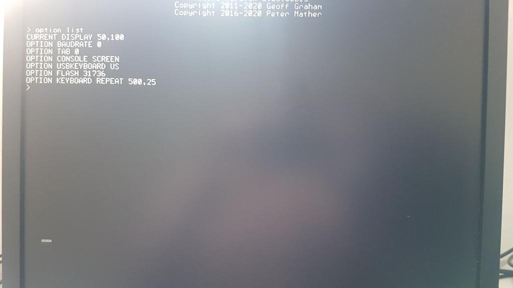 PS.: Look at the giant corrupted cursor. Edited 2020-12-05 04:59 by MauroXavier |
||||
| matherp Guru Joined: 11/12/2012 Location: United KingdomPosts: 11513 |
Try b14 just posted. I've just been through your sequence and it works perfectly Do an erase all before flashing. Also try putting the switch into SYSTEM mode then reset to enter flashing rather than UPDATE FIRMWARE Finally, remove battery when flashing and put it back in once flashed Edited 2020-12-05 05:07 by matherp |
||||
| MauroXavier Guru Joined: 06/03/2016 Location: BrazilPosts: 307 |
Full flash enabled and b14... Cursor corrupted and OPTION FLASH 31736 as default. I will try other things to see if I see it´s something here that is causing it. |
||||
| matherp Guru Joined: 11/12/2012 Location: United KingdomPosts: 11513 |
Try as follows: Plug in A-A USB Switch Waveshare to SYSTEM Press RESET You should get the MS connected noise Into CubeProgrammer Connect to USB Go to download screen Click on the top select checkbox to select all sectors click Erase Selected Sectors You should see confirmation of each sector being erased in turn Check "Skip flash erase before programming", we don;t need to erase twice Make sure "Verify programming" is also checked click Start Programming Click message boxes Click disconnect Move switch back to FLASH press reset Check Options look sensible |
||||
| MauroXavier Guru Joined: 06/03/2016 Location: BrazilPosts: 307 |
Tried exactly as you said, and the result is the same: 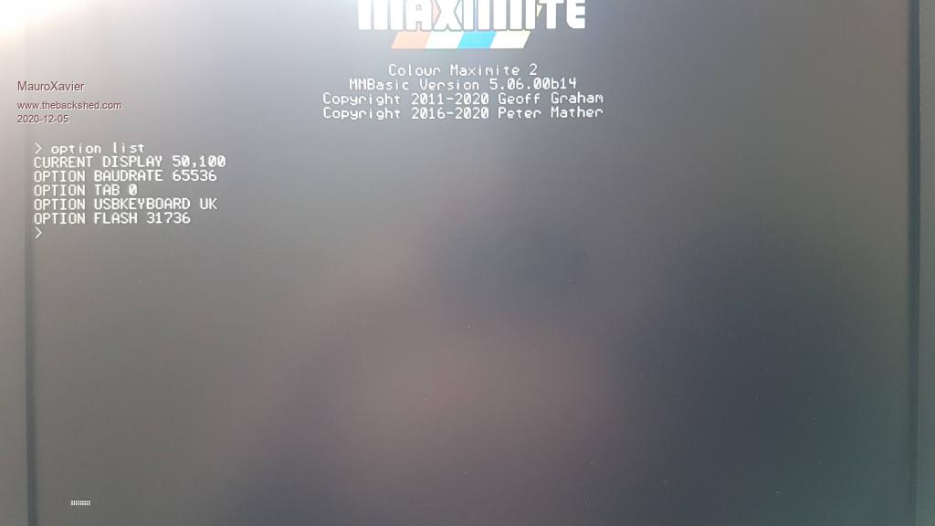 |
||||
| matherp Guru Joined: 11/12/2012 Location: United KingdomPosts: 11513 |
What happens if you now go OPTION RESET |
||||
| JohnS Guru Joined: 18/11/2011 Location: United KingdomPosts: 4335 |
I wonder if the corruption is a sign that (say) the last part of the file is not programmed correctly (or maybe at all)? Maybe round up the size of the bin file to a multiple of (er, 512? 1K?) by padding with 0xff (&HFF) bytes. John |
||||
| toml_12953 Guru Joined: 13/02/2015 Location: United StatesPosts: 657 |
That's what I've been trying to tell people! Maybe they'll listen to you. |
||||
| The Back Shed's forum code is written, and hosted, in Australia. | © JAQ Software 2026 |
