
|
|
Forum Index : Microcontroller and PC projects : PicoMite/PicoMiteVGA V5.07.05 betas
| Author | Message | ||||
| matherp Guru Joined: 11/12/2012 Location: United KingdomPosts: 11671 |
Manual page 47(VGA) or 72 |
||||
| phil99 Guru Joined: 11/02/2018 Location: AustraliaPosts: 3325 |
Is this any good? ? �MM.INFO(CPUSPEED) 378000000 > ? mm.ver 5.070511 > I type too slowly. Edited 2022-06-26 22:19 by phil99 |
||||
| thwill Guru Joined: 16/09/2019 Location: United KingdomPosts: 4379 |
Thanks guys, Not sure how MM.INFO(CPUSPEED) and MM.INFO(OPTION CPUSPEED) could possibly be equivalent, and I so wanted to type an extra keyword  . .Best wishes, Tom MMBasic for Linux, Game*Mite, CMM2 Welcome Tape, Creaky old text adventures |
||||
| Volhout Guru Joined: 05/03/2018 Location: NetherlandsPosts: 5999 |
@Peter, I was investigating the audio filter, as I promised, and noticed the audio tone does not play well. Please see below graph, there are 2 places where the sine wave is not continuous, but distorted. I excluded everything (i.e. SD card/system I2C). Virgin VGA mite MMBasic 05.07.05b11 OPTION AUDIO GP6,GP7 PLAY VOLUME 100,100 PLAY TONE 1000,1000 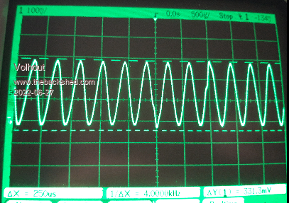 Software 05.07.04 (Geoff's official release) does not have this. Maybe it has some latency in stitching the waveforms together in the PWM. It is independent of the frequency. It may be (little) less in lower volume, but that may be due to oscilloscope triggering, missing these events. They are not only visible on the scope, you can hear these distortions as short ticks in the audio. To the ear maybe a bit random. FYI in these tests I run the picomite without USB connection, so it is not the USB stack I guess... It is better audible at 2kHz or 4kHz. If you think you get mad from the sine waves in your ear: PLAY STOP is your best friend... EDIT: in a full system with SD card you can see hear the artefact in the tone command emphasized if you PLAY TONE 2000,2000 FILES Edited 2022-06-27 01:57 by Volhout PicomiteVGA PETSCII ROBOTS |
||||
| Witenite Newbie Joined: 02/06/2022 Location: New ZealandPosts: 8 |
Just injecting myself into the conversation here. I have also done some investigation into the audio quality using an oscilloscope. I too noticed some distortion, and the distortion gets exponentially worse as you go up in frequency. This is to be expected given the very rude/crude first order filter used to filter the output PWM signal. I noticed that above about 8 or 10kHz, a PWM sinewave no longer resembles anything like a sinewave anymore. This distortion is consistent across the entire waveform though, and not the same distortion that you are seeing. I suspect the waveform is probably becoming distorted when the PWM duty cycle is being updated perhaps. If you like, I can do some more comprehensive analysis and come back to the forum and post my findings. Happy to help. Another option I have been seriously thinking about, is instead of outputting PWM and filtering it, what about generating an I2S (or failing that, I2C) serial output. This could use the same pins as the PWM output, so a user (or a PCB design) could use either option. An I2S input/audio output chip like a CS4344 would be a perfect choice for this, and produce far better quality audio than the current solution. So an end user may opt to either use the PWM (lowest cost) or I2S (add about $5 - $7 to the cost of the build) for far superior audio. This means though that MMBASIC would have to port I2S audio out on the PicoMite, which means a yet more software development (sorry Peter!). Probably have to use PIO for this, as I don't think the Pico board has native I2S support. Failing this there may be an I2C audio option too. That's my 2 cents worth, let me know what you think.  |
||||
| matherp Guru Joined: 11/12/2012 Location: United KingdomPosts: 11671 |
This would also be true if you played a 10Khz tone on a CD (4 samples per sinewave) I will try and fix the bug Volhout has found but I'm not going any further than that on audio. However, I need a better low-pass filter to see the bug before I can see and fix it. Volhout, can you confirm if the frequency stays correct when you see the glitch or is it a runt sinewave? UPDATE: just realised my oscilloscope (Picoscope) has a programmable low pass filter. Using this I can't replicate the bug seen in Volhout's trace Edited 2022-06-27 19:29 by matherp |
||||
| Volhout Guru Joined: 05/03/2018 Location: NetherlandsPosts: 5999 |
@Peter, When the artefact happens the frequency of that particular since cycle is different (I measured a lower frequency, one I remember was 3.9kHz versus 4.2kHz for other cycles). I estimate one PWM update is "late" and a sample is PWM-ed twice. @Witenite Yes, when the amount of "samples" per since cyle gets lower the odd harmonics increase. And for a 5kHz sine wave the 3'rd (15kHz) is within audio range and gets through UN-attenuated. So your sine wave doesn't look nice at all. For 8kHz, the 24kHz is in the filter falloff, and may get attenuated, but with only 5 samples per sine, the inaccuracy will be huge. 10kHz .... even worse. When your goal is to get the nicest sine waves, then the low pass filter should drop of much earlier, and you have to live with an audio bandwidth of less than 10kHz. And that is not a curse. My transistor active filter has a really nice slope, and starts to rolloff at 10kHz. The 5 and 8kHz waveforms look nice, and it is very acceptable to listen to music (CD quality from SD card). But nothing above 10kHz..... PicomiteVGA PETSCII ROBOTS |
||||
| thwill Guru Joined: 16/09/2019 Location: United KingdomPosts: 4379 |
Hi folks, Is the issue being chased also the one that causes my rendition of The Entertainer (entertainer.zip) to be very "clicky" at 126 MHz ? If not then (as @Volhout indicated in a different thread) the problem is presumably with either notes / Sine waves being interrupted before they are "complete" or with the implementation of rests (currently as "inaudible" notes, but temporarily stopping a channel is also clicky). I would appreciate any advice as to how I could overcome this problem without having to devote significantly more CPU time to the music playback in my game. Best wishes, Tom Edited 2022-06-27 21:02 by thwill MMBasic for Linux, Game*Mite, CMM2 Welcome Tape, Creaky old text adventures |
||||
| Mixtel90 Guru Joined: 05/10/2019 Location: United KingdomPosts: 8981 |
@ matherp When you did the recent change to make port writes simultaneous (or, if not actually simultaneous, near enough), did it also make port reads simultaneous? Mick Zilog Inside! nascom.info for Nascom & Gemini Preliminary MMBasic docs & my PCB designs |
||||
| Tinine Guru Joined: 30/03/2016 Location: United KingdomPosts: 1646 |
 Been meaning to ask. Been meaning to ask.I tested CAT, yesterday and it's definitely faster with only 2 strings but not for more. Edit: meaning that I had to do multiple CATs. Craig Edited 2022-06-29 08:21 by Tinine |
||||
| matherp Guru Joined: 11/12/2012 Location: United KingdomPosts: 11671 |
No. But will do in the next beta |
||||
| Mixtel90 Guru Joined: 05/10/2019 Location: United KingdomPosts: 8981 |
Thanks Peter. :) Mick Zilog Inside! nascom.info for Nascom & Gemini Preliminary MMBasic docs & my PCB designs |
||||
| matherp Guru Joined: 11/12/2012 Location: United KingdomPosts: 11671 |
PicoMite V5.07.05b13 https://geoffg.net/Downloads/picomite/PicoMite_Beta.zip Adds beta support for the 480x320 IPS ILI9341 display (use code ILI9341N) Modifies the port function to read all pins simultaneously Updates SDK to V1.4 Updates Compiler to version 11.2.1 |
||||
| Mixtel90 Guru Joined: 05/10/2019 Location: United KingdomPosts: 8981 |
Great! Thanks, Peter. :) Mick Zilog Inside! nascom.info for Nascom & Gemini Preliminary MMBasic docs & my PCB designs |
||||
| Witenite Newbie Joined: 02/06/2022 Location: New ZealandPosts: 8 |
Thanks Volhout for the detailed explanation. My experience has been in PWM filter development for very low frequencies only (power systems, 50Hz/60Hz) so while the theory and math is identical, the objectives and observations are quite different. Is there a reference or link to the active filter you have designed? I wouldn't mind assembling one myself and trying it out. It sounds like it is still a very low cost solution. Low cost is a characteristic I always enjoy playing with, especially when you can achieve entirely acceptable results. Anybody can throw a $1000 DAC solution at a problem, but it takes particularly skilled engineering to produce a good quality $5 solution. Discrete designs make for more hardware fun and learning too for newcomers (people such as students, that I am especially passionate about attracting into the industry). @Peter Yes I am well aware of PWM resolution for CD audio (2 samples per cycle at 20kHz for example), however at 10kHz I was expecting to at least see something that was quasi-sinewave, or exhibiting 4 samples per cycle. All I saw was a consistent sawtooth waveform with no sinusoidal shape or modulated output at all, at 10kHz. I fully appreciate I'm being pedantic here though, given the incredible cost and resource constraints of this little system, so don't get me wrong, I'm already beyond impressed at what you have achieved here. A pity we/you can't look further into an I2S audio implementation for the hardware, but I completely understand as you have already cleared a mountain of tasks here, and certainly have more than enough on your ToDo list as it is. We can revisit at a later date. If you guys need me to test anything or produce some decent oscilloscope data/images, just shout. Happy to help, and I have a couple of Pico's on my workbench, ready to roll. |
||||
| phil99 Guru Joined: 11/02/2018 Location: AustraliaPosts: 3325 |
Distortion of frequencies above 10kHz isn't all that important, for humans at least, as all the harmonics are above 20kHz and inaudible. I imagine few of us here can hear much above 15kHz. For me the limit is now down to 12kHz so above 4kHz a square wave, which only has odd harmonics, sounds the same as a sine wave. |
||||
bigmik Guru Joined: 20/06/2011 Location: AustraliaPosts: 2981 |
G�day Peter, All, Shouldn�t that be ILI9481 (and Code ILI9481N)? Regards, Mick Edited 2022-07-03 08:28 by bigmik Mick's uMite Stuff can be found >>> HERE (Kindly hosted by Dontronics) <<< |
||||
| bigmik Guru Joined: 20/06/2011 Location: AustraliaPosts: 2981 |
Hi All, Peter, There appears to be a minor issue with that release Peter, The 0,0 point is set for top right instead of Top left (at least with the ILI9481N driver) 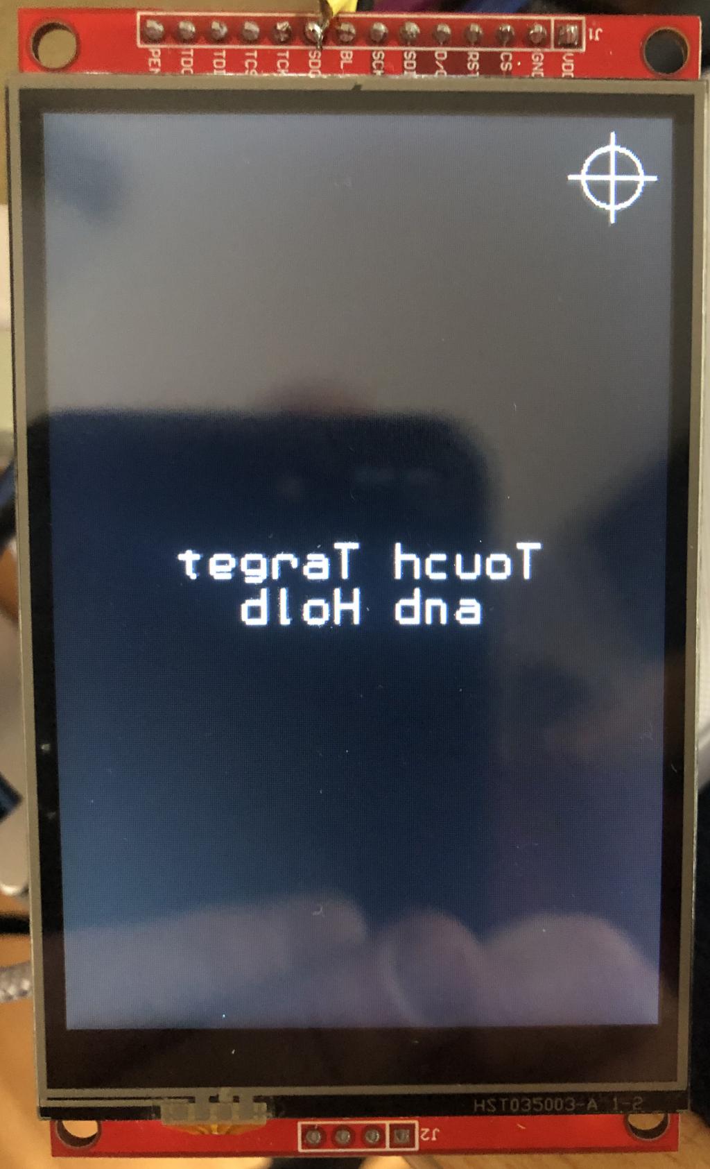 It is probably my fault as I didnt notice that the test for MISO reads was colouring the pixels at the top right instead of top left. Well I did notice that was where the pixel was being set but it didnt click that it was the wrong corner. Sorry about that FYI these are my option settings: OPTION SYSTEM SPI GP18,GP19,GP16 OPTION AUTORUN ON OPTION CPUSPEED (KHz) 125000 OPTION LCDPANEL ILI9481N, PORTRAIT,GP15,GP14,GP13,GP20 OPTION TOUCH GP12,GP11 GUI CALIBRATE 1, -167, 2043, 1267, -1737 OPTION SDCARD GP22 Regards, Mick Mick's uMite Stuff can be found >>> HERE (Kindly hosted by Dontronics) <<< |
||||
| matherp Guru Joined: 11/12/2012 Location: United KingdomPosts: 11671 |
Mick Can you try all 4 orientations and let me know which are correct and which not - thanks |
||||
| Mixtel90 Guru Joined: 05/10/2019 Location: United KingdomPosts: 8981 |
About time I did another compilation file of the Beta releases. :) V5 07 05 Betas Info..pdf Mick Zilog Inside! nascom.info for Nascom & Gemini Preliminary MMBasic docs & my PCB designs |
||||
| The Back Shed's forum code is written, and hosted, in Australia. | © JAQ Software 2026 |
