
|
|
Forum Index : Microcontroller and PC projects : PicoMite/PicoMiteVGA V5.07.05 betas
| Author | Message | ||||
| matherp Guru Joined: 11/12/2012 Location: United KingdomPosts: 10247 |
I've done more checking on the audio and don't think there is a bug in the firmware. Attached is the output of my scope of a 10KHz waveform (PLAY TONE 10000,10000). The bottom trace is the actual pwm output. The top trace is the same data passed through a digital filter with a 5KHz knee. Inspection of the bottom trace shows that there are no "odd" pulses and the filtered output appears perfect. I have made one tiny change to the priority of the audio interrupt in b13 but since I couldn't demonstrate any issue in earlier versions I can't see if this has had any effect 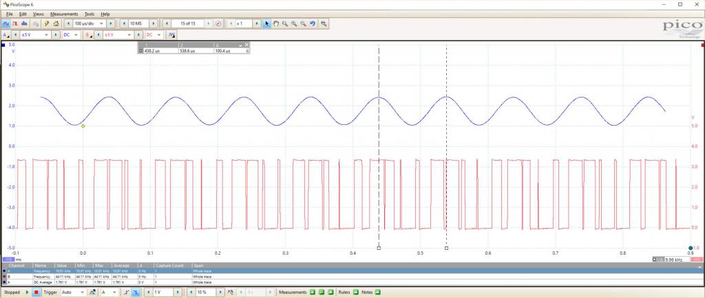 |
||||
| Volhout Guru Joined: 05/03/2018 Location: NetherlandsPosts: 5063 |
Thanks for looking at it! I am not sure if it van be found with your setup. Your low pass filter may hide the artefacts because the rolloff at 5k(*) and I had to use deep memory at the scope to make it visible (at 10khz you may need 10000 cycles before you capture one). If it really is the wrap around interrupt, feed it to a gpio pin, put the scope in persistent mode, you can see if it is stable, and always equally wide pulse width. Volhout (*) I assume you need this to suppress the 44kHz sufficiently. PicomiteVGA PETSCII ROBOTS |
||||
bigmik Guru Joined: 20/06/2011 Location: AustraliaPosts: 2949 |
Hi Peter, All, This was very hard to describe so I have compiled pictures, ALL photos are taken with the display in the same physical orientation as can be seen by the white USB lead on the top left of each image. I will leave it to you to work out what needs to change 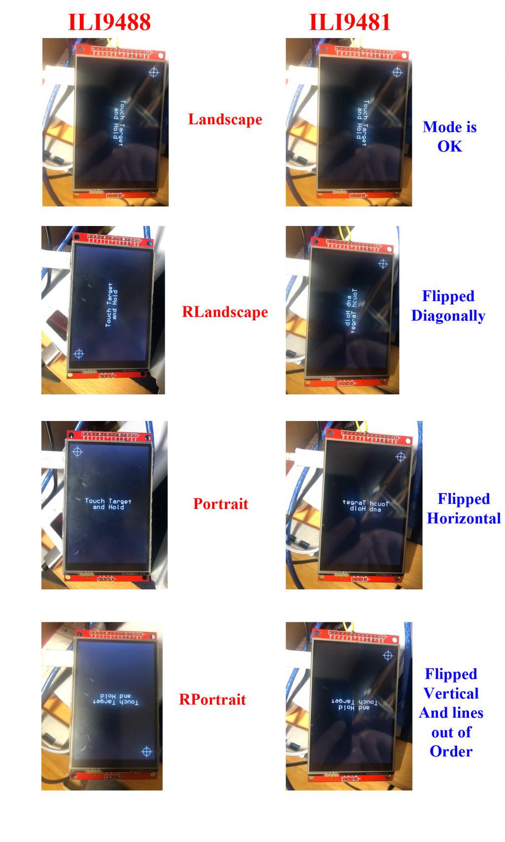 Kind Regards, Mick Mick's uMite Stuff can be found >>> HERE (Kindly hosted by Dontronics) <<< |
||||
| matherp Guru Joined: 11/12/2012 Location: United KingdomPosts: 10247 |
Mick Thanks for the pics - looks like they have wired this display different from the normal ILI9481. It will take multiple iterations to get right. Are you around for lots of trial and error? Peter |
||||
| bigmik Guru Joined: 20/06/2011 Location: AustraliaPosts: 2949 |
Hi Peter, All, It is all part of the fun. If you are prepared to write some code I am prepared to test it for you. I will monitor this thread every hour or so and test when family pressure permits. Now I have the ILI9488 to compare to it is an easy thing for me to test all of the modes. It is a sunny day today so I hope to try the two types in full sunlight and compare the differences. In the subdued lighting in my room it doesn�t seem much different. Regards, Mick Edited 2022-07-04 09:33 by bigmik Mick's uMite Stuff can be found >>> HERE (Kindly hosted by Dontronics) <<< |
||||
| phil99 Guru Joined: 11/02/2018 Location: AustraliaPosts: 2612 |
A very minor issue with PWM, it only accepts GP numbers. If this is intended could that be noted in the manual entry for the PWM command? PicoMiteVGA MMBasic Version 5.07.05b13 > setpin 1, pwm > pwm 1,10000,50 Error : Pin not set for PWM > pwm gp0,10000,50 > no error with GP0 |
||||
| bigmik Guru Joined: 20/06/2011 Location: AustraliaPosts: 2949 |
Hi All, I went outside to test the 2 screens (ILI9481 and ILI9488) side by side and the results are interesting. In direct Sunlight both displays were equally poor, neither could be read. In the shade, similarly, both displays were more or less identical and both could be read easilly. When Inside I had a really close look at them side by side and the following observations were made The BLACK on the ILI9481 is marginally blacker than the ILI9488, The ILI9488 fades as you look from an angle (starting at around 45 degrees) and the black background starts to go paler shades of grey from around 30 degrees viewing angle. The ILI9481 on the other hand is viewable from as sharp an angle as I could look at it, even looking almost edge on and the black maintains its blackness So I would think the ILI9481 might be a better choice overall, especially if Peter can improve the speed of the driver somehow. I was going to try to take pictures but that was pretty hard getting both displays to be the same angle and heights etc and realistically it is mainly the viewing angle that is the main difference. Hope this helps you decide on the best choice for your purpose. Regards, Mick Mick's uMite Stuff can be found >>> HERE (Kindly hosted by Dontronics) <<< |
||||
| Mixtel90 Guru Joined: 05/10/2019 Location: United KingdomPosts: 7873 |
@phil99 A bit inconsistent :) It's good practice to always use the GP numbers anyway. Absolute pin numbers only apply to the original Raspberry Pi Pico module and won't necessarily work on anything else. They are not RP2040 pin numbers either. The GP numbers are a shortened form of the GPIOnn numbers used on the RP2040 chip so are compatible with all platforms. Mick Zilog Inside! nascom.info for Nascom & Gemini Preliminary MMBasic docs & my PCB designs |
||||
| matherp Guru Joined: 11/12/2012 Location: United KingdomPosts: 10247 |
Mick Please try the attached PicoMite.zip Sorry but it's user error. Check the manual. Pin one is on PWM channel 0. The PWM GP0 works because gp0 in this case is an uninitialised variable with the value 0 Try SETPIN 1,pwm pwm 0,10000,50 Edited 2022-07-04 16:53 by matherp |
||||
| bigmik Guru Joined: 20/06/2011 Location: AustraliaPosts: 2949 |
Hi Peter, All, Same same but different. There are changes from earlier but the 3 modes are still incorrect 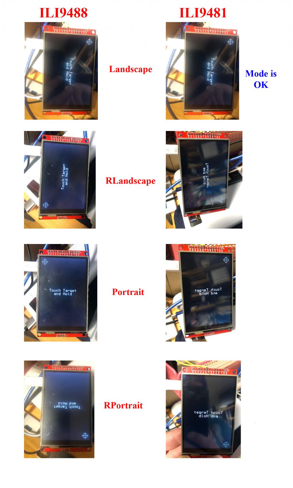 It is interesting that in PORTRAIT mode the Target is in the same place as previously but the Text is chr by chr flipped horizontally. Kind Regards, Mick Edited 2022-07-04 18:12 by bigmik Mick's uMite Stuff can be found >>> HERE (Kindly hosted by Dontronics) <<< |
||||
| phil99 Guru Joined: 11/02/2018 Location: AustraliaPosts: 2612 |
@matherp Thanks for the explanation. |
||||
| Volhout Guru Joined: 05/03/2018 Location: NetherlandsPosts: 5063 |
@Peter, I have tried your b13 (tried the VGA version) and the audio problem can still be found. I am not sure if it is a software issue. AFAIK the PWM runs stand alone and only the capture/compare register is updated with sine samples. Is this a DMA thing ? Or is the ARM putting new values in (under interrupt?). Anyway, when the compare register is updated at the wrong moment you may get a whole 44kHz cycle that is faulty. But this would happen far more frequent I guess. Anyway, the faults in the audio happen at "random" moments, but sometimes they happen around the peaks of the sine wave, leading to a higher peak value. When the sine wave is 3.3Vpp, the level cannot get any higher, but if you use a higher frequency, the filter rolloff will attenuate the sine wave to a lower level, and the peak can be used to trigger the scope. But you need a hardware filter to change the PWM to a sine wave. So what I do is: PLAY TONE 16000,16000 With my current test filter, this gives a 1.5Vpp sine wave (with intermodulation). Then I trigger the scope at 0Vdc and adjust the trigger upward until (single shot) I get a trigger. You can clearly see the fault. 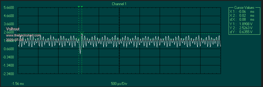 This is the filter I currently use (these components where in my bin) 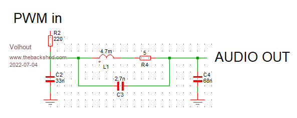 These "glitches" occur also at the high side. Why am I using this method, of a frequency in the rolloff of the filter ? Let's assume the values put into the PWM are the correct values. But they are simply delayed for some cause. The delay causes the frequency (temporary) to be lower, and lower frequencies are not attenuated that much, so they lead to higher levels. And levels you can trigger easily on a scope. If you look at the markers in the oscilloscope picture, you see that these are 0.08ms appart. This means that in the 16kHz (62us) since wave there is one 12kHz (80us) cycle. So there is an 18us delay in the update of (one of the ? ) values of the sine wave. Edit: the 18us is close enough to 22us, the cycle time of the PWM. Maybe the new value misses the pwm update slot, and the previos value is repeated once more, before, in the next slot the new value is used. Pwm updates are most likely hardware synchronized with the wrap around of the counter in the pwm. Edited 2022-07-05 02:36 by Volhout PicomiteVGA PETSCII ROBOTS |
||||
| matherp Guru Joined: 11/12/2012 Location: United KingdomPosts: 10247 |
PicoMite V5.07.05b14 https://geoffg.net/Downloads/picomite/PicoMite_Beta.zip New commands: BITBANG SERIALTX pinno, baudrate, ostring$ BITBANG SERIALRX pinno, baudrate, istring$, timeout_in_ms, status% [,nbr] [,terminators$] Allows serial I/O on any pins. status% returns: -1 = timeout (NB: use len(istring$) to see number received) 2 = number of characters requested satisfied 3 = terminating character satisfied baudrate in both cases 110-230400 (230400 may need CPU to be overclocked). NB: both commands are blocking and both disable interrupts during operation. ILI9481N renamed to ILI9481IPS, driver still in beta and only correct in landscape Edited 2022-07-05 18:01 by matherp |
||||
| bigmik Guru Joined: 20/06/2011 Location: AustraliaPosts: 2949 |
GDay Peter, All, Did you notice the latest photos I attached the other day. Peter? I did it in the same format as the original comparison so you may have thought it was the original and not a new comparison. Regards, Mick Edited 2022-07-05 18:40 by bigmik Mick's uMite Stuff can be found >>> HERE (Kindly hosted by Dontronics) <<< |
||||
| matherp Guru Joined: 11/12/2012 Location: United KingdomPosts: 10247 |
Mick - yes thanks. I will give up until my board arrives to avoid wasting both our times |
||||
| bigmik Guru Joined: 20/06/2011 Location: AustraliaPosts: 2949 |
Fair enough Peter, I have many other board options to keep me happy. Regards, Mick Mick's uMite Stuff can be found >>> HERE (Kindly hosted by Dontronics) <<< |
||||
| Martin H. Guru Joined: 04/06/2022 Location: GermanyPosts: 1221 |
Hi, after the BLIT Command is no longer in future MM-Basic versions, Will it be possible to give the Srites an attribut which makes them opaque? 'no comment |
||||
| lizby Guru Joined: 17/05/2016 Location: United StatesPosts: 3362 |
What does this refer to? I searched this entire thread, and the only other reference to BLIT was not related to this. PicoMite, Armmite F4, SensorKits, MMBasic Hardware, Games, etc. on fruitoftheshed |
||||
| Martin H. Guru Joined: 04/06/2022 Location: GermanyPosts: 1221 |
it refers to the Topic :PicoMiteVGA V5.07.05 betas So, naive as I am, I thought that I could ask questions, relating to PicoMiteVGA V5.07.05 betas. 'no comment |
||||
| Mixtel90 Guru Joined: 05/10/2019 Location: United KingdomPosts: 7873 |
I've not been keeping up with the Beta releases. Silly me. I have two PicoMites here and I've tried b14 on both. I got one to synch ok for a short period (but I don't know how), but both have bad line tearing, making the characters all but unreadable. I tried nukeing the flash, getting a new download and trying again but it was the same. I've just returned one of them to 5.07.04 and it's fine. Both can be accessed via the console ok. I'm assuming that it's my monitor that's not quite flexible enough to capture Hsync properly. Has anyone else had screen problems with the betas? EDIT: I've just tried to get the monitor to auto-synch. It didn't work. Reported frequencies are 30kHz horizontal and 59kHz vertical. I managed to get another synch. The heartbeat LED was continuously on and the keyboard was dead. Edited 2022-07-07 06:05 by Mixtel90 Mick Zilog Inside! nascom.info for Nascom & Gemini Preliminary MMBasic docs & my PCB designs |
||||
| The Back Shed's forum code is written, and hosted, in Australia. | © JAQ Software 2025 |
