
|
|
Forum Index : Microcontroller and PC projects : Circuit diagram
| Author | Message | ||||
| HankR Senior Member Joined: 02/01/2015 Location: United StatesPosts: 209 |
Might take a few days to get around to doing a decent drawing, so for now a description in words. One can arrange an inverting NPN stage with collector resistor (Common emitter) feeding into the existing PNP section just as it is now. This shifts the "reference" of the uC pin to ground (conventional) and allows for separate and different value voltages feeding the uC and the switched loads. Because of the inversion with the NPN stage, now a uC high provides current to a switched load. A uC low turns off load current. |
||||
lew247 Guru Joined: 23/12/2015 Location: United KingdomPosts: 1709 |
ok I've gone back to the original npn transistors I know this will work, even with a bit of a voltage drop if fed from the 4.7 or 5v rail there will be plenty of voltage to power the modules as each one works from anything between 2.6-5.5V When the pin goes high the transistor conducts and will let the voltage through to the module, simple transistor switch! |
||||
bigmik Guru Joined: 20/06/2011 Location: AustraliaPosts: 2981 |
Hi Lew, All, I think you are mistaken there as well... You are trying to get say 4.5V to your GPS module... Assuming you could get 4.5v there the voltage at the base cannot go above 3v3 so the transistor would be turned OFF hence you couldn't get 4.5V to the GPS... Basically the concept is wrong.. Going back to the PNP transistor circuit.. If you put a 10k bias resistor from Base to emitter you would get the following. Set the mite pin an OUTPUT and set it LOW and the transistor will turn on allowing power to the GPS module. Set the mite pin to an INPUT allows the 10k resistor to pull the base to 5V turning the transistor OFF.. Now that is OK if you use a 5V tolerant mite pin.. but if not you will need a schotkey protection diode (anode to the mite pin and cathode to 3v3) Regards, Mick Mick's uMite Stuff can be found >>> HERE (Kindly hosted by Dontronics) <<< |
||||
| bigmik Guru Joined: 20/06/2011 Location: AustraliaPosts: 2981 |
GDay Lew, All, Probably the easiest way is to use an opto isolator as in this circuit 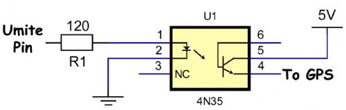
They are fairly cheap and will only draw power when ON (the LED side is set for about 10mA.) Regards, Mick Mick's uMite Stuff can be found >>> HERE (Kindly hosted by Dontronics) <<< |
||||
| MicroBlocks Guru Joined: 12/05/2012 Location: ThailandPosts: 2209 |
How much current can a opto isolator typically switch. Would having a transitor that is switching to ground not be a solution? 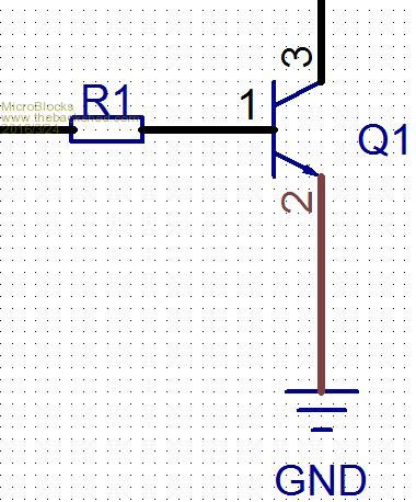
Microblocks. Build with logic. |
||||
| bigmik Guru Joined: 20/06/2011 Location: AustraliaPosts: 2981 |
Hi Jean, I thought of that but you `might' get some sort of powering the GPS (or other module) through the TX/RX lines... as the 5V will need to be connected permanently to the module... Probably not a good idea.. I am interested in feed back from others. How much current does the GPS module actually draw? Personally I think keep it continuously powered up and use a XIOAMI power bank that is topped up via a mains source...but I understand mains may not be available in all situations. Regards, Mick Mick's uMite Stuff can be found >>> HERE (Kindly hosted by Dontronics) <<< |
||||
| lew247 Guru Joined: 23/12/2015 Location: United KingdomPosts: 1709 |
Look at the diagram below The module itself brings the transistor to ground 
|
||||
| MicroBlocks Guru Joined: 12/05/2012 Location: ThailandPosts: 2209 |
Yes the TX/RX lines would need to be 'unconnected' when the GPS is not powered, maybe to be save also add a resistor in the TX/RX lines, maybe 100 ohm is enough. In the uMite it could be done by setting those pins to OFF with the SETPIN command. I think it can work if you do the sequence right. To activate the GPS, setup the comport, activate the power. To deactivate, close the comport,deactivate power. The pins would then automatically be configured by the OPEN and CLOSE commands, preventing some leaking currents from the TX/RX lines. From the MMBasic manual: [code] When a serial port is opened the pins used by the port will be automatically set to input or output as required and the SETPIN and PIN commands will be disabled for the pins. When the port is closed (using the CLOSE command) all pins used by the serial port will be set to a not-configured state and the SETPIN command can then be used to reconfigure them. [/code] Thinking about it a bit more.... if switching to ground that also means the GPS module has to be isolated, mounting screws might be grounded and give a path for the current.... hmmm. Looks like the opto is the easiest option. Microblocks. Build with logic. |
||||
| lew247 Guru Joined: 23/12/2015 Location: United KingdomPosts: 1709 |
How about this as a solution>? and obviously the same with the gps module transistor 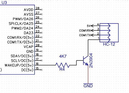
|
||||
| lew247 Guru Joined: 23/12/2015 Location: United KingdomPosts: 1709 |
I know the HC-12 module works with the Micromite when powered direct by 5v, I've tested it and the gps modules for several days All I need to do is turn the 5v power on and off with the micromite pin |
||||
| lew247 Guru Joined: 23/12/2015 Location: United KingdomPosts: 1709 |
The other options is this 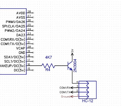
|
||||
| bigmik Guru Joined: 20/06/2011 Location: AustraliaPosts: 2981 |
Lew, If you look at your diagram (the one in 5V line) you can see that the Maximum voltage (with respect to GND) that can appear at the BASE is 3v3. Giving a best case of 0.6V drop across the b-e junction would mean the maximum output voltage that could appear is 3.3-0.6 or 2.7V.. But in practice I think you will find that the GPS module would not power up. The 2nd diagram with the transistor in the GND line is technically feasible but, as MB has stated, you would have to isolate the GND of the module from anything else and you have the problem of `bleed through the TX and RX lines when the transistor is OFF.. It `may' work OK, well it would probably work as a GPS solution but will it still draw more current than you wish to draw when it is OFF?? If you have a module why not try it and do some current measurements? Do you know the max current draw of the GPS? Even the OPTO (4N35) I drew may not work as it (the datasheet is a bit confusing to me) seems to have a max `operating' current of 50mA but you would need to feed the LED side with about the same which the uMite will not do (max about 15mA)... Back to the drawing board me-thinks.. best the dual transistor drive circuit Hank suggested.. or a miniature relay or solid state relay.. Mick Mick's uMite Stuff can be found >>> HERE (Kindly hosted by Dontronics) <<< |
||||
| lew247 Guru Joined: 23/12/2015 Location: United KingdomPosts: 1709 |
I would try it if I had some transistors here along with a working micromite, I don't have either unfortunately |
||||
| lew247 Guru Joined: 23/12/2015 Location: United KingdomPosts: 1709 |
Due to problems with the switching of the transistor I've had to modify the circuit I'm informed this should work perfectly now 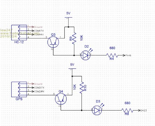
|
||||
| MicroBlocks Guru Joined: 12/05/2012 Location: ThailandPosts: 2209 |
What about using this: http://ww1.microchip.com/downloads/en/devicedoc/21422d.pdf It has two channels, so only one DIP-8 chip is needed. You would need the inverting TC4426. Pull the input up to 5v and use a 5v tolerant uMite pin to put a LOW on the input of the TC4426. Microblocks. Build with logic. |
||||
| lew247 Guru Joined: 23/12/2015 Location: United KingdomPosts: 1709 |
It's a driver for a fet so I'd need to add 2 fet's as well I'm pretty certain it will work fine as it is now BTW MicroBlocks (or anyone) How do I change the setting on Diptrace so I can see the traces on the bottom of the board (or the top again afterwards) ? |
||||
| MicroBlocks Guru Joined: 12/05/2012 Location: ThailandPosts: 2209 |
No the FETS are part of the chip. It is a complete circuit to get from a logic level to an output 'switch' that can have more current. Only one resistor per channel needed. I think this would be how to use them. 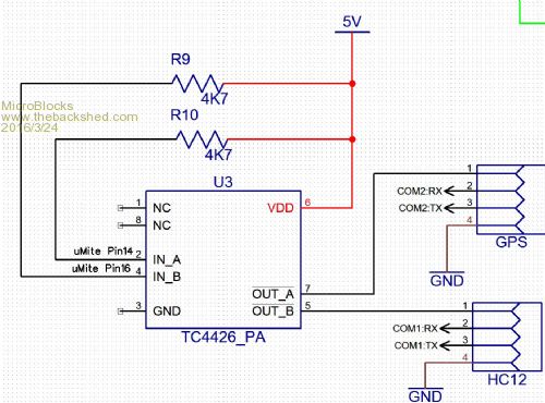
I don't have the part so i can not test. They look interesting so i have ordered a few. As for the layers in DipTrace: Press 1 for top, 2 for bottom. Or use the little listbox in the toolbar to choose the layer. If you not see that listbox, press F6 to enable/disabled the route toolbar. You can also check which toolbars are visible under the menu View->Toolbars Microblocks. Build with logic. |
||||
| lew247 Guru Joined: 23/12/2015 Location: United KingdomPosts: 1709 |
Thanks for that Jean, I never noticed that toolbar or maybe I had it hidden. That part does look interesting but for not I'll stick with transistors 
2016-03-24_192723_DipTrace_Schematic_-_Weather_17.pdf |
||||
| lew247 Guru Joined: 23/12/2015 Location: United KingdomPosts: 1709 |
MicroBlocks is the part you used on your board, the screw terminals part of the standard Diptrace package? I've been looking but cant find it |
||||
| bigmik Guru Joined: 20/06/2011 Location: AustraliaPosts: 2981 |
Hi Lew, I hate being the Harbinger of DOOM But..... I really do not understand that circuit at all, the way I see it the Emitter-Base junction will work as a diode and effectively be permanently supplying power to the LED/load.. Unless someone can show me the error behind my thinking and explain how that circuit works... I have a simple Idea I will post in a future message.. I am not entirely dismissing that circuit as I honestly cannot understand how it would work and my transistor theory is rusty at best. Regards, Mick Mick's uMite Stuff can be found >>> HERE (Kindly hosted by Dontronics) <<< |
||||
| The Back Shed's forum code is written, and hosted, in Australia. | © JAQ Software 2026 |
