
|
|
Forum Index : Microcontroller and PC projects : Armmite F4: programming the firmware
| Author | Message | ||||
| lizby Guru Joined: 17/05/2016 Location: United StatesPosts: 3758 |
Perfect. Thank you for this powerful addition to the micromite family. PicoMite, Armmite F4, SensorKits, MMBasic Hardware, Games, etc. on FOTS |
||||
| Modelguy Newbie Joined: 27/06/2019 Location: United StatesPosts: 1 |
Hello, I am a newbe to flashing these processors. I have ordered a unit and screen as described by Matherp, but in the waiting period to get it, I wanted to ask if the mmbasic port to the F4 would work on the stm32f4291 disco board, which I have. I am interested in learning about the inertial chip, but don't speak "c". Fortran was my type language many years ago. |
||||
| lizby Guru Joined: 17/05/2016 Location: United StatesPosts: 3758 |
Touch behavior has me puzzled. If I power on and download (F10) and run the program below, touch works to go from my opening screen with a [MENU] button to my menu selection screen and back (and on again and back). If I terminate with Ctrl-C and "run" again, the program doesn't respond to a touch. Neither does it respond to Ctrl-C--no return to ">". If I press the reset button, I can "run" again and all works until I press Ctrl-C and run again. This is on the F4 with MMBasic from June 22 and the standard display. [code] option base 1 dim integer i,vLoc,iButtonHeight,iPage,menuPos,iFlagMenuTouch=0,maxItems=10 dim integer iTouchX,iTouchY,iTouchBox(4) const cBlack=0,cWhite=&HFFFFFF,cRed=&Hff0000,cGreen=&H00FF00 const cCyan=&H00FFFF, cGray=&H808080,cLightGray=&HD3D3D3 GUI interrupt TouchDown,TouchInt vLoc=mm.fontheight*2 iButtonHeight=5+mm.fontheight iTouchBox(1)=mm.hres-(mm.fontwidth*7) ' left of first " " in " MENU " iTouchBox(2)=vLoc-8 ' top of first " " in " MENU " iTouchBox(3)=mm.hres-mm.fontwidth ' end last of " " in " MENU " iTouchBox(4)=vLoc+mm.fontheight ' bottom of last " " in " MENU " do iPage=1 cls vLoc=mm.fontheight*2 box mm.hres-mm.fontwidth*7,vLoc-8,mm.fontwidth*6.5,iButtonHeight,,,cCyan text mm.hres-(mm.fontwidth*6.5),vLoc-6," MENU ",L,,,cBlack,cCyan do ' wait for a touchup action on page 1 if iFlagMenuTouch=1 then iFlagMenuTouch=0 showMenu iTouchX = -1: iTouchY = -1 do ' wait for a touchup action on page 2 ' if iTouchX > 0 and iTouchY > 0 then if menuPos > 0 then print menuPos;" Selected exit do endif ' endif loop exit do endif loop loop end sub TouchInt ' interrupt activated when screen touch release (touch up) print "Page ";iPage;" Touch at "+str$(iTouchX)+","+str$(iTouchY) menuPos=-1 if iTouchX > 0 then if iPage = 1 then ' print "Touch at "+str$(iTouchX)+","+str$(iTouchY) if iTouchX >= iTouchBox(1) and iTouchX <= iTouchBox(3) then if iTouchY >= iTouchBox(2) and iTouchY <= iTouchBox(4) then print "MENU area touched" iFlagMenuTouch=1 endif endif elseif iPage = 2 then ' menu page if iTouchX > mm.fontwidth*14 and iTouchX < mm.fontwidth*32 then ' range for menu selection if iTouchY > (mm.fontheight+2)*2 and iTouchY < (mm.fontheight+2)*(maxItems+3) then menuPos=iTouchY/(mm.fontheight+2)-2 endif endif endif endif end sub ' TouchInt Sub showMenu local integer vLoc,inputs,loopCount local string sMenu(maxItems) length 20 = ("1. Mode OFF","2. Mode AUTO","3. Mode HEAT","4. Mode COOL","5. Blower ON","6. Blower OFF","7. Replace GEOsets","8. Renew Display","9. Enter Date/Time","CANCEL") const buttonDown=2,buttonSelect=1 iPage=2 cls vLoc=0 text mm.hres/2,vloc,"Select Item",C,,,cWhite,CBlack vLoc = (mm.fontheight+2)*2 menuPos=1 for menuPos=1 to maxItems text mm.fontwidth*14,vloc,sMenu(menuPos),L,,,cWhite,CBlack vLoc=vLoc + mm.fontheight+2 next menuPos menuPos=0 end sub ' showMenu sub TouchDown ' don't do anything on touch down--only touch up iTouchX=TOUCH(X) iTouchY=TOUCH(Y) end sub [/code] PicoMite, Armmite F4, SensorKits, MMBasic Hardware, Games, etc. on FOTS |
||||
| matherp Guru Joined: 11/12/2012 Location: United KingdomPosts: 11351 |
Thanks for the report - I'll look at it but won't have a chance until later in the week/next week |
||||
| lizby Guru Joined: 17/05/2016 Location: United StatesPosts: 3758 |
After OPTION LCDPANEL DISABLE, I'm trying to set up one of the hres-480 SSD1963 LCDs using your adapter (Peter's) with OPTION LCDPANEL SSD1963_4, LANDSCAPE The response is "Error: Argument count" What is the proper setup for this? Also for the 7" SSD1963? Also what should be done with the 3-pin header labelled "5V" on the left and "BL" on the right? PicoMite, Armmite F4, SensorKits, MMBasic Hardware, Games, etc. on FOTS |
||||
| matherp Guru Joined: 11/12/2012 Location: United KingdomPosts: 11351 |
OPTION LCDPANEL SSD1963_n_16,orientation Only 16-bit drivers are implemented on the F7 Only needed for 7" display (connect to external 5V supply) or PWM'd 5V |
||||
| lizby Guru Joined: 17/05/2016 Location: United StatesPosts: 3758 |
Thank you. I found that for the 4.5" 480x272 LCD, I had to connect 5V to the pin on the adapter, and bridge 5V to the middle pin on the BL 3-pin connector. With this I was able to paint the screen. However, I couldn't get GUI CALIBRATE to work. The first two targets presented successfully, but after I touched the second one, I got "Error: Touch hardware failure". This LCD worked (some months ago) on the H7. PicoMite, Armmite F4, SensorKits, MMBasic Hardware, Games, etc. on FOTS |
||||
| matherp Guru Joined: 11/12/2012 Location: United KingdomPosts: 11351 |
It is possible I have the SPI data lines transposed. If you can find a way of patch wiring to test this it would be appreciated. I haven't got one of the boards. WW was having some made but they seem to have gone missing in the post. SO, SI, T_DO, T_DIN, SPI2-OUT, SPI2-IN, MOSI, MISO aaaaargh!!!!!! |
||||
| lizby Guru Joined: 17/05/2016 Location: United StatesPosts: 3758 |
I feel your pain. It does appear to me that T_DO and T_DIN are reversed with respect to MOSI and MISO, but when I break the links and re-wire--successfully according to my DMM--I get multicolored vertical lines on the screen, and no response (on the screen) to commands. Back to the original adapter--it displays properly but GUI CALIBRATE fails. I've checked again and again, but don't see what I'm doing wrong with the swap. (And with respect to "aaaaargh", every time I look at this LCD stuff my brain gets turned upside down and inside out.) I'll be happy to send you a couple of the adapters, if you like. Post from Canada is pretty quick. Or if you wish to make the changes you think are appropriate and publish the gerbers, I'll order 10 of them and send you 5. PicoMite, Armmite F4, SensorKits, MMBasic Hardware, Games, etc. on FOTS |
||||
| matherp Guru Joined: 11/12/2012 Location: United KingdomPosts: 11351 |
I'll send you a PM with my address. Probably best if I get the original working before changing the layout and getting it wrong again  NB I don't think you should need to connect anything to the headers on a 4.3" display if you set the backlight control jumper on the display to 1963_PWM but I'll check this out as well once I have one of the boards |
||||
| lizby Guru Joined: 17/05/2016 Location: United StatesPosts: 3758 |
I'll mail two of the SSD1963 LDC adapter boards tomorrow. Hadn't tried that permutation. It works with jumper on the BL side and no 5V, but very faint. I tried BACKLIGHT nn up to BACKLIGHT 99 without seeing a difference. Switch jumper to 5V and connect 5V on the F4 board to 5V on the LCD adapter, and all is good, sharp and bright. .251A consumed. PicoMite, Armmite F4, SensorKits, MMBasic Hardware, Games, etc. on FOTS |
||||
| Volhout Guru Joined: 05/03/2018 Location: NetherlandsPosts: 5884 |
Finally my STM32F407evp6 board arrived with the LCD. Flashing worked fine, thanks for the detailed description. Problem: It was not recognized by Windows through USB. Tried re-flashing it 3 times. No luck. Tried waiting minutes and reconnecting. No luck. Googled around for this problem. Found a hint about removing R21, tried that, no luck. And something about clocks not on the right frequency. Have no idea how to influence that in a boot loader. Will go look for a serial interface. May have a 1455 somewhere. Otherwise this board becomes a brick in the dust bin. PicomiteVGA PETSCII ROBOTS |
||||
| Volhout Guru Joined: 05/03/2018 Location: NetherlandsPosts: 5884 |
@matherp, Have you used this info to create the MMbasic software for the F4? Maybe it has something that could lead to a solution for the USB not found �. https://blog.brichacek.net/wp-content/uploads/2015/10/STM32F4-and-USB.pdf Regards, Volhout PicomiteVGA PETSCII ROBOTS |
||||
| matherp Guru Joined: 11/12/2012 Location: United KingdomPosts: 11351 |
The code uses the standard STM supplied libraries and I can promise it works fine. What version of Windows are you using? STM provide a driver for versions other than W10 which doesn't need one. 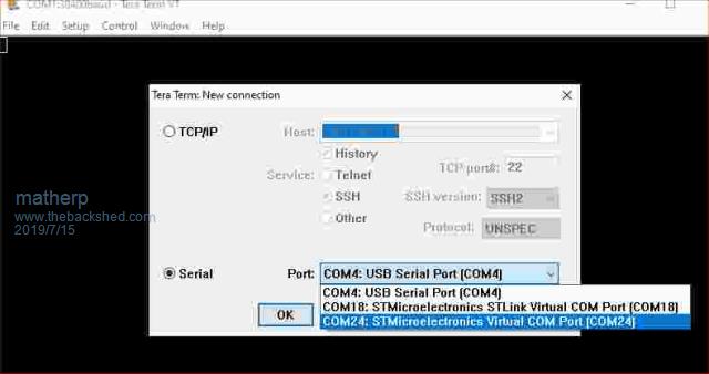 Given that you programmed the board (presumably over USB?) we know the clocks etc are fine and the wiring is OK on your board. |
||||
| Volhout Guru Joined: 05/03/2018 Location: NetherlandsPosts: 5884 |
Hi matherp, Using W10. So that shouldn't be the cause. As far as I can interpret the W10 popup it doesn't get the ID's when USB is plugged int. And there is a popup that the device had an error "last time it was connected". As if that applies to the programming itself. But the programmer reported success. As instructed, I closed the programming software. Now I think of it.. But I did not do a "safe removal".... Maybe that is essential. Not sure. After the success in programming and verification I closed the Cube programmer, and pulled the USB. I will try the safe disconnect tonight. PicomiteVGA PETSCII ROBOTS |
||||
| matherp Guru Joined: 11/12/2012 Location: United KingdomPosts: 11351 |
Also worth trying a good quality cable if you are using the one supplied and, of course, do the programming with the screen disconnected. |
||||
| Volhout Guru Joined: 05/03/2018 Location: NetherlandsPosts: 5884 |
@matherp / lizby, Tried a bit more with the F4 board, but could not get it to work. Output in device manager: Device USB\VID_0000&PID_0002\5&aea7634&0&1 was not migrated due to partial or ambiguous match. Last Device Instance Id: USB\VID_04D8&PID_FA8D\5&aea7634&0&1 Seems like when changing the bt0/bt1 bits it starts as a different device (VID/PID), but still has the same ID. Maybe clearing the registry is needed to get it recognised. PicomiteVGA PETSCII ROBOTS |
||||
| matherp Guru Joined: 11/12/2012 Location: United KingdomPosts: 11351 |
Serial port I get USB\VID_0483&PID_5740 DFU bootloader device I get USB\VID_0483&PID_DF11 Always worth trying a different USB port for the different modes of use. Are you using a laptop? USB power issue? |
||||
| lizby Guru Joined: 17/05/2016 Location: United StatesPosts: 3758 |
Sorry to hear about your problems. After some initial difficulties with the first F4 I tried, I've now got 6 of them working--some with the original cables and some with new. I have no idea why it didn't work at first but then did (original flashing of MMBasic with the STM32CubeProgrammer worked every time). Hate to ask, but you're sure you have the jumper positions changed from those for flashing to those for MMBasic programming as shown in the first post of this thread? On Win7 laptops, I had to install a driver, but not for Win10. You might try flashing the version with OPTION SERIAL built in (on page 4 of this thread). Then you could see if you can connect to console via usb/serial to COM1. That won't be the best long-term solution, though--you probably couldn't expect updates. Wish I could offer more concrete advice. Good luck. PicoMite, Armmite F4, SensorKits, MMBasic Hardware, Games, etc. on FOTS |
||||
| erbp Senior Member Joined: 03/05/2016 Location: AustraliaPosts: 195 |
Hi, This problem sounds exactly like the one I had with my first board - see my earlier posts in this thread (pages 4 & 5 I think). The down side to the USB Console is that if the firmware fails to initialize properly, then it stops processing and either doesn't setup the USB connection properly, or because it has stopped it doesn't respond to the Windows request for a Device Descriptor. Either way Windows can't talk to the device and displays the sort of error messages you are seeing. The version of firmware that @lizby referred to on page 4 was a special mod created by @matherp for me when I was trying to figure out my problem. It has OPTION SERIAL CONSOLE ON set by default, so doesn't try to use the USB Console, but you need a UART/USB module connected to J6. In my case once I had this setup in place I could see that the firmware was reporting "Error: Invalid Pin" during initialization, and therefore stopped running at that point - it never displayed the startup banner and copyright messages. You will never see this via the USB Console as the connection hasn't been successfully established at that time. I eventually ordered (from a different vendor) and received another F4 which works correctly, so the assumption is that the original board/chip has a defect. Maybe one day I'll investigate it further. I do recommend trying the Serial Console enabled version of the firmware (with a serial console connected of course), I think it is the only way you are likely to find out if there is a problem initializing the firmware. This may still mean that your board is a dud, but at least it might give certainity one way or other. Cheers, Phil. |
||||
| The Back Shed's forum code is written, and hosted, in Australia. | © JAQ Software 2026 |
