
|
|
Forum Index : Microcontroller and PC projects : Armmite F4: programming the firmware
| Author | Message | ||||
| JohnS Guru Joined: 18/11/2011 Location: United KingdomPosts: 4038 |
Quite an interesting PDF but is there one with English that isn't mangled into garbage? (It doesn't seem relevant to this reported problem, though.) John |
||||
| matherp Guru Joined: 11/12/2012 Location: United KingdomPosts: 10240 |
Please find attached a new version. 2019-07-17_011424_ArmmiteF4.zip This includes most of the changes Geoff has included in his latest beta release so is a biggish change and should also be considered a beta. In addition it fixes a bug relating to touch when a program is terminated with Ctrl-C. It also fixes "GUI RESET LCDPANEL" for the ILI9341 default display. Geoff's changes: Further optimised the storage of programs in flash memory. Added the command AUTOSAVE CRUNCH. This instructs MMBasic to remove all comments, blank lines and unnecessary spaces from the program before saving. This can be used on large programs to allow them to fit into limited memory. CRUNCH can be abbreviated to the single letter C. Added the command XMODEM CRUNCH. This acts the same as XMODEM RECEIVE except that it "crunches" the program in the same manner as AUTOSAVE CRUNCH. Added the command GUI FORMATBOX. This has a popup keypad which can be used to enter a date, time, latitude, etc in a fixed format. For example, it can be used to get a latitude in the format: dd� mm' ss" N/S. See FormatBox.pdf in this distribution. Geoff's bug fixes : A space is now added after the question mark ("?") shortcut when it is translated into the PRINT command. Fixed a bug in STR$() where it did not correctly position the sign when the padding was set to a zero character ("0"). Removed the ability to have MM.KEYPRESS called from the GUI NUMBERBOX and TEXTBOX controls. There were too many issues with getting this feature to run reliably. This functionality has been partially replaced by GUI FORMATBOX (see above). Fixed a bug which prevented GUI HIDE from operating on a page not currently displayed. On small displays the GUI NUMBERBOX numeric keypad is now displayed and erased correctly (previously it could corrupt the display). Also fixed an issue where sometimes the invoking box itself was erased from the screen when the number pad was deployed. Fixed a small issue with the brightness of a GUI SWITCH caption when depressed. Corrected a bug which could cause a GUI radio buttons in two separate frames to interfere with each other. The GUI MsgBox() function will now wait for any touch to be lifted before taking over the screen. |
||||
| RonnS Senior Member Joined: 16/07/2015 Location: GermanyPosts: 121 |
I also have the problem that after the flash of, the USB port is not found Ron UPDATE 10 mins later disconnected the LCD and flasch the new MM Basic Version an it seems to work thanks Matherp |
||||
Chopperp Guru Joined: 03/01/2018 Location: AustraliaPosts: 1095 |
Bugger!!! Accidentally cracked the LCD screen on one of my F4's the other day. Board went dead. Wouldn't reboot. Screen OK (apart from the cracks) on the other F4 (touch not tested). Tried uploading the HEX file after setting the jumpers but the module itself wouldn't even come up properly on the USB controllers List:- "Unknown USB Device (Device Descriptor Request Failed)" Tried different leads & USB ports etc to no avail. I was having fun at the time. Put a damper on that. Like to know what I did to destroy it. Brian Edit. Successfully updated good board ChopperP |
||||
| erbp Senior Member Joined: 03/05/2016 Location: AustraliaPosts: 195 |
I believe you do have the SPI data lines reversed. I have just connected up an East Rising 9" LCD to my ARMMite F4. Below is the list of connections that I used between the LCD connector on the F4 module and the LCD screen connector. 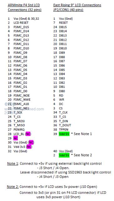 As shown I have ARMmite LCD connector pin 25 (T_MOSI) connected to ER LCD pin 35 (T_DIN - this would be pin 22 on a standard SSD1963 LCD connector) and ARMmite LCD connector pin 26 (T_MISO) connected to ER LCD pin 36 (T_DOUT - this would be pin 26 on a standard SSD1963 LCD connector). This arrangement is working properly, I have been able to perform the GUI CALIBRATE without any issues and GUI TEST TOUCH works ok as does the display on the LCD. Hope this info helps. Cheers, Phil. |
||||
| lizby Guru Joined: 17/05/2016 Location: United StatesPosts: 3358 |
Phil--thanks for your testimony that Peter's adapter should work with Din and Dout swapped. And it does. I don't know what I had done wrong the first umpteen times I tried it (maybe had the wrong LCDPANEL selected), but now GUI CALIBRATE works with no problem, as does GUI TEST TOUCH. Thank you for encouraging me to revisit this. Now I can go back to trying to see if I can get the 7" SSD1963 to work after I rewire another F4 LCD adapter. Did you produce a PCB adapter for the Earth Rising panel? Shareable? PicoMite, Armmite F4, SensorKits, MMBasic Hardware, Games, etc. on fruitoftheshed |
||||
| lizby Guru Joined: 17/05/2016 Location: United StatesPosts: 3358 |
Much easier to make the change on a new SSD1963 adapter after I know the other one worked. And the new one worked as well with the 4.3" SSD1963. I set up a different F4 with the original working adapter and plugged in the 7" SSD1963 (which worked yesterday evening on an H7 hat board). Here are my options: > option list OPTION LCDPANEL SSD1963_7_16, LANDSCAPE OPTION TOUCH PB12, PC5 > The panel doesn't flash on power-up, and doesn't respond to GUI CALIBRATE. I don't think it is getting enough power. I have it wired the same as the 4.3" LCD, with 5V from the F4 board connected to 5V on the adapter, and the backlight shorted to the 5V side. The F4 is connected to USB on the laptop. I'm connecting through a voltage and current display. With the 4.3" panel, the current jumps to .250A. With the 7" panel, it settles at .105A. What should I do to power the panel and F4 when using the 7" panel? PicoMite, Armmite F4, SensorKits, MMBasic Hardware, Games, etc. on fruitoftheshed |
||||
| erbp Senior Member Joined: 03/05/2016 Location: AustraliaPosts: 195 |
No, I didn't create a PCB adapter. This is only a temporary arrangement so I just used a set to 10cm female-female dupont wires. Originally from a 40-way set, I separated all the wires I actually used from each other so they could easily cross-over / head in different directions as the pin connections do jump around a bit. Cheers, Phil. PS. re your power question. I have all but given up using USB power from PC's, especially laptops. I have a couple of adapters made up in small cases that have a mini-USB connector to accept a std USB cable connection from a PC and another regular USB connector - the same type as the one that would be on the PC/laptop. I only connect Ground and D+/D- from the mini-USB to the regular USB "output" connector (so a data only connection). Then I have a few power connectors (whatever type you like - I have 1 x 2.1mm barrel socket, 1 x 2.5mm barrel socket and another mini-USB). I only connect Ground and +5v from these connectors to the regular USB "output" connector. This allows me to have a USB data connection to the PC, but inject +5v from some other (more capable) power source. It works a treat and eliminates many USB power related issues. |
||||
| lizby Guru Joined: 17/05/2016 Location: United StatesPosts: 3358 |
Thank you. I had wondered about a power arrangement like that. The H7 + 7" SSD1963 draws .785A at 5V. But I had wondered if a beefier 5V in would matter if the 3.3V regulator on the F4 was unable to handle the extra current draw anyway. I guess your experience shows that it will. I see that the regulator on the F4 is an AMS1117, rated for 1A. So I guess with your D+, D-, and 0V on the usb connector, one could feed a heftier 5V+0V to the COM1 header pins. Does that sound safe? Do you know what the draw is for your 9" East Rising LCD with the F4? PicoMite, Armmite F4, SensorKits, MMBasic Hardware, Games, etc. on fruitoftheshed |
||||
| erbp Senior Member Joined: 03/05/2016 Location: AustraliaPosts: 195 |
Current draw for the F4 + ER 9" is .74A when displaying a black screen and .69A when displaying a white screen. The J2 connector on the F4 has +5v connections on the top 2 rows of pins (4 pins in total - the ones nearest the USB connector). I feed power in via them rather than the single +5v pin on J6. J2 also has 2 Ground pins in row 5. As long as you don't also have a power connection via the USB plug using the J2 pins should be perfectly safe. |
||||
| erbp Senior Member Joined: 03/05/2016 Location: AustraliaPosts: 195 |
Does anyone have instructions on how to upload from the F4 to create a customised firmware load file? I can't even find where to start an upload from in the STM32 CubeProgrammer.  Phil. |
||||
| matherp Guru Joined: 11/12/2012 Location: United KingdomPosts: 10240 |
Minor update attached. I've changed the USB enumeration code to request 500mA rather than 100mA. May or may not help with higher power TFT. 2019-07-19_223042_ArmmiteF4.zip 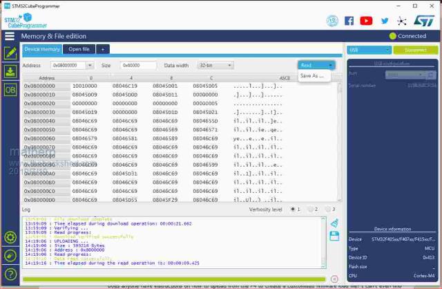 |
||||
| erbp Senior Member Joined: 03/05/2016 Location: AustraliaPosts: 195 |
@matherp - Thanks, I didn't see the "Save As..." option in the Read drop down.  Unfortunately the image is a little blurred - can you please confirm the Address value is 0x08000000 and the Size is 0x6000? Unfortunately the image is a little blurred - can you please confirm the Address value is 0x08000000 and the Size is 0x6000?Thanks, Phil. |
||||
| matherp Guru Joined: 11/12/2012 Location: United KingdomPosts: 10240 |
0x60000 not 0x6000 |
||||
| lizby Guru Joined: 17/05/2016 Location: United StatesPosts: 3358 |
I've been unable to get the 7" SSD1963 LCD to respond on the F4. With the new software (5.05.08) and just the usb connection, I have no response to GUI CALIBRATE. Here's the power arrangement I cobbled together to try to supply more: 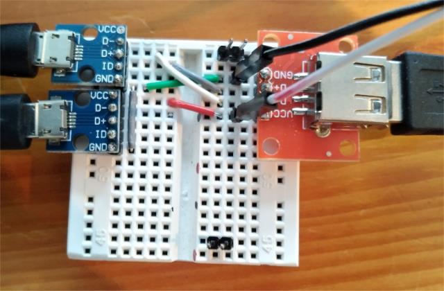 The micro USB breakout adapter on the upper left (plugged into a laptop USB port) has power not connected, D+, D-, and GND connected to the adapter on the right, which plugs into the F4 USB connector. The micro USB breakout adapter on the lower left is plugged into a power plug which provides up to 2.1A. It has successfully powered r-pi-zws. The white and black dupont wires on the breadboard are plugged into 5V and 0V respectively on the F4. 5V and 0V on the F4 are connected to 5V and 0V on the LCD adapter. For BL, 5V is jumpered. This also gives me no response to GUI CALIBRATE. A current sensor on the power plug only shows .134A. I would expect something in excess of .500A since on the H7, this LCD draws .785A, .295A with the LCD disconnected (but with the H7 adapter on). OPTION LIST gives this: > option list OPTION LCDPANEL SSD1963_7_16, LANDSCAPE OPTION TOUCH PB12, PC5 > Any thoughts about what I should try next? PicoMite, Armmite F4, SensorKits, MMBasic Hardware, Games, etc. on fruitoftheshed |
||||
| erbp Senior Member Joined: 03/05/2016 Location: AustraliaPosts: 195 |
@matherp - you will probably remember that I had a problem with my original F4 module (see page 4/5 of this thread). With your help I eventually discovered that it was reporting "Error: Invalid pin" when the firmware attempted to start and we supposed either the chip or module to be faulty. I bought another F4 which works fine. I have done some more investigation with the "dud" module. First I loaded the most recent (19-July) firmware - loads and verifies ok, but still doesn't run. I then took my good module, also loaded with the most recent firmware, and did an OPTION LCDPANEL DISABLE to clear the pre-configured LCDPanel and Touch options. OPTION LIST then returns an empty list. I also did an OPTION SERIAL CONSOLE ON so that I could use a serial console since the USB console is useless when the firmware fails to run. I then used STM32 CubeProgrammer to upload a copy of the firmware from the good module to a PC file, swapped to the "dud" module and downloaded the file just created. With a serial console attached I then fired up the "dud' module and it now works  - no "Error: Invalid pin" reported. Futhermore I was then able to manually re-enter the LCDPanel and Touch options (using the same values as the pre-configured setup) and again no errors reported. I was able to do a GUI CALIBRATE without problems, and so far it seems to successfully run any test that I have tried. I have been able to switch back to USB Console mode too and that works as well. - no "Error: Invalid pin" reported. Futhermore I was then able to manually re-enter the LCDPanel and Touch options (using the same values as the pre-configured setup) and again no errors reported. I was able to do a GUI CALIBRATE without problems, and so far it seems to successfully run any test that I have tried. I have been able to switch back to USB Console mode too and that works as well. I'm glad it didn't bin this module, as it is not such a dud after all.  I thought you would be interested to know this. I thought you would be interested to know this.Cheers, Phil. |
||||
| matherp Guru Joined: 11/12/2012 Location: United KingdomPosts: 10240 |
Try bridging LED_A to the pin next to it labelled 5V on the adapter 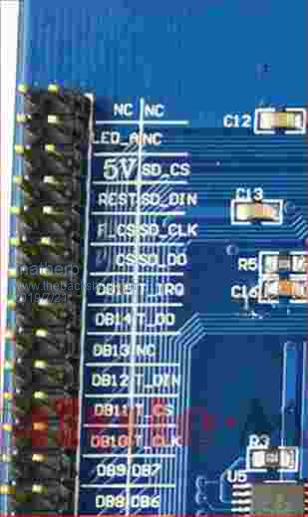 |
||||
| erbp Senior Member Joined: 03/05/2016 Location: AustraliaPosts: 195 |
@lizby - I tried my SSD1963 7" LCD on a F4 tonight and I couldn't get it to display anything sensible (using the same option settings as in your post). It did display a faint "pattern" - kind of tiny checkerboard rectangles covering the entire screen, but it was very hard to see, certainly no display from a GUI TEST LCDPANEL command, nor a CLS with various background colours tried. It seemed to ignore GUI CALIBRATE and GUI RESET LCDPANEL didn't show any visible changes either. Phil. |
||||
| lizby Guru Joined: 17/05/2016 Location: United StatesPosts: 3358 |
Bingo! Thanks. On first power-up, I got a current draw of .555A (good news)--but many colors on the screen. I'd gotten that before with the 4.3" LCD, and had found that RESET would fix it (maybe several times with different screen patterns)--and it did for the 7" with one RESET press. Still no response to GUI CALIBRATE. But I fiddled some more, downloaded my program again, RESET several times, and then, with no wiring changes, GUI CALIBRATE worked, as did GUI TEST TOUCH and CLS, and my program. So thanks very much. (FYI doesn't work with this particular 7" LCD when the F4 is just plugged straight into a USB port, though the current draw jumps to .443A.) PicoMite, Armmite F4, SensorKits, MMBasic Hardware, Games, etc. on fruitoftheshed |
||||
| lizby Guru Joined: 17/05/2016 Location: United StatesPosts: 3358 |
Next step: I tried a 9" EastRising 800x480 SSD1963 with Grogster's Adapter plugged into Peter's adapter (same one that worked for the 7" SSD1963). I suppose this is like the one erbp got working with (I think) flying leads. It drew .218A, but didn't respond. Do I need the two outer 2x4 sockets? Anything else likely necessary? PicoMite, Armmite F4, SensorKits, MMBasic Hardware, Games, etc. on fruitoftheshed |
||||
| The Back Shed's forum code is written, and hosted, in Australia. | © JAQ Software 2025 |
