
|
|
Forum Index : Electronics : 150V 45A MPPT - roll your own
| Author | Message | ||||
| poida Guru Joined: 02/02/2017 Location: AustraliaPosts: 1478 |
Mike, the above code was just a start. It does not work as a matter of fact. proc_mppt_test_2_works.zip does work and works well. n/N alter the noise, k/K moves the "knee" of the current curve left or right. In the case of the buck converter, PWM width is directly proportional to the ratio of input and output voltages. With the mppt controller I am designing, pwm width is proportional to the "operating voltage" of the solar panel, i.e. input voltage. I have found that with the low impedence wiring I used in the 2 boards, I saw only very small changes in PWM width when I alter the current that is output. I find pwm width to be a close analog to input voltage. The code determines input voltage from the pwm width. I use 800 units of pwm width, 1 unit to 800 units wide. I map this 1 to 800 units to 0 to 50V (Vmax in the code) I do not care about output voltage or battery charging in this test code. I just want to see a peak search function work. And still work with noise. Give the attached file a go and see what you see. Now I have functioning perturb and observe code, and I have improved it to be capable of working well with a noisy signal, I am ready to start on the controller firmware. It only took me 3 hours here at work. What can I can to do while I am still here? I'm bored. All the electronics is located at home. wronger than a phone book full of wrong phone numbers |
||||
| poida Guru Joined: 02/02/2017 Location: AustraliaPosts: 1478 |
thanks for the pointer to these chips. I bought a couple ages ago and I agree they are a much better choice than opamps. The ones I got can be used on the high or low side. Just pick a resistor and that sets the gain. I keep coming back to the LEM sensors. I get 3 of them for free from an Aerosharp board. Just give it 5V and you get a bipolar output. 3 wires. Isolation is inherently obtained from the package design. wronger than a phone book full of wrong phone numbers |
||||
| poida Guru Joined: 02/02/2017 Location: AustraliaPosts: 1478 |
Both boards are quite stable enough right down to about 1 Amp output. I think I will just switch off output once the battery/charge program thinks it needs less. A 400AH battery will not miss the 1 Amp much. And once the battery voltage drops a little, it will suck up more than 1 A and so the controller will switch back on, running Absorb or float constant voltage. When running mppt, it is assumed the battery is more than somewhat less than the absorb voltage. This will probably ensure continuous mode is present. Discontinuous mode is stable right down to very small pwm widths that are fractions of an Amp at 30V in, 15V out test conditions. Transition from night (i.e. zero input power) to something small might well place the controller in a situation where the pwm control becomes unstable. That is to be seen at a later date for me. First I build a robust buck converter, then mppt tracking, then mppt/absorb transition, then night to daytime and back transition. I think there is plenty to do. But I get yer drift with this. I am a hacker, not an engineer so I will find a way, the only thing is the way could be inelegant and crazy. wronger than a phone book full of wrong phone numbers |
||||
| poida Guru Joined: 02/02/2017 Location: AustraliaPosts: 1478 |
here is a video of the mppt tracking, running the program contained in the zip file above I change the knee position of the current curve, which of course alters the location of the power peak. It works nicely. With less noise it finds the peak faster. https://youtu.be/HkBr3sKRzKo wronger than a phone book full of wrong phone numbers |
||||
| Warpspeed Guru Joined: 09/08/2007 Location: AustraliaPosts: 4406 |
Yup. You have it all pretty well mapped out. With sufficient early sun, the battery voltage here can zoom up to max in maybe only one hour, the current then quickly tapers right down too, and the remaining part of the day it can be charging at less than one amp. Inelegant and crazy is fine. Some pretty strange and unconventional engineering can work extremely well. Just because something is totally weird and unique and has probably never been done before, does not mean its not a practical solution. Cheers, �Tony. |
||||
| poida Guru Joined: 02/02/2017 Location: AustraliaPosts: 1478 |
0.6% RMS tracking error. Not too bad with this amount of noise. proc_mppt_test_2_works.zip 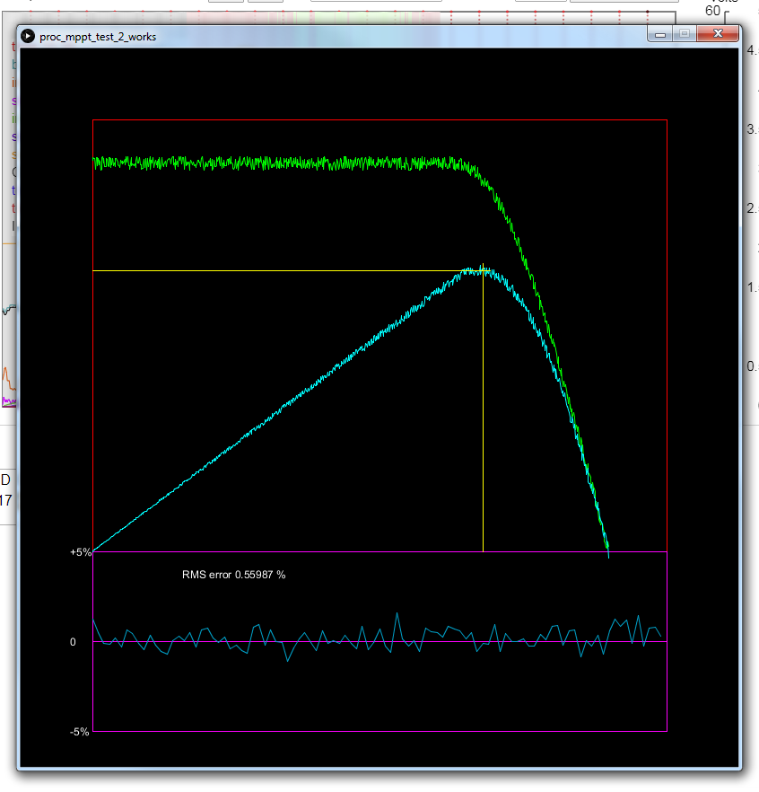 Edited 2020-04-28 15:43 by poida wronger than a phone book full of wrong phone numbers |
||||
disco4now Guru Joined: 18/12/2014 Location: AustraliaPosts: 1128 |
I am not 100% sure but I think the problem maybe only when i is used as the index variable. i enclosed by square brackets looks like html start of italics. I have tried j to see what happens below void init() { int i,k; float v,kv,t; for (i=0; i < np; i++) { v = 50.0 * (float)(i)/(float)(np-1); if (v < vknee) amps[i] = imax ; else { t = (vmax - v)/(vmax - vknee); kv = cos((1.0 - t)*3.14159*0.5); amps[i] = kv * imax ; } volts[i] = v; } } void init() { int j,k; float v,kv,t; for (j=0; j < np; j++) { v = 50.0 * (float)(j)/(float)(np-1); if (v < vknee) amps[j] = imax ; else { t = (vmax - v)/(vmax - vknee); kv = cos((1.0 - t)*3.14159*0.5); amps[j] = kv * imax ; } volts[j] = v; } } F4 H7FotSF4xGT |
||||
| wiseguy Guru Joined: 21/06/2018 Location: AustraliaPosts: 1296 |
Peter, the mppt video you posted is a great demonstration example - it appears to work a treat. I cant find my bench at the moment to play with anything electronic - its about 3 layers deep in "stuff" being sorted.... I need to do a lot of culling but I cant bear to throw out all this "good stuff" (my wife calls it junk......) And thanks Noneya for the TI current sense part comment, I did not know it existed and it looks like a very good addition for my go to bits bin. Edited 2020-04-29 10:18 by wiseguy If at first you dont succeed, I suggest you avoid sky diving.... Cheers Mike |
||||
| nickskethisniks Guru Joined: 17/10/2017 Location: BelgiumPosts: 478 |
Hi, good work Poida! Something different, last week I was doing some research and testing on gate drivers. It was then that I noticed that the absence of a 10uF capacitor can result in some gate ringing during turn on. (It's not specific 10uF but small buffer Cap is realy needed) I tested with a Fod3182 driver, I was driving 3 mosfets irfp4110 �with 5R switch off resistor and 20R turn on resistor each fet. BTW, I've got a lot of questions about how to switch a mosfet, I think I'm going to open a neww thread about it. Edited 2020-04-29 21:15 by nickskethisniks |
||||
| poida Guru Joined: 02/02/2017 Location: AustraliaPosts: 1478 |
nickskethisniks, I have built 2 boards, with variations on MOSFET types. board #1 has a 100uF and a Tantalum of unknown value positioned side by side under the TLP205 socket. board #2 has a 10uF 16V Tantalum and 100u cap. I used the 12V-12V isolated single supply part so the 16V Tant cap is OK. I notice your schematic uses a 12V-15V bipolar output and uses -15 and +15 outputs to supply the TLP250. I think that is a bit high and wanted to try 12V for gate drive and see what happens. As it happens board #1 has less ringing than #2. Last night I finally got MPPT working on a board (and not just simulated in software) It works fine. I found that from a cold start, MPPT does not work at all for me, but every minute the code does as scan from 1/16th power to 15/16ths power and records the pwm that produces maximum power. Then I start MPPT from that point and it works flawlessly. The reason I will incorporate the periodic max. power scan is due to shading of parts of an array can cause multiple power peaks. My MPPT code will not find always the maximum peak among a few, it will just track to the top of the first one it sees. the paper from here shows some potential situations. 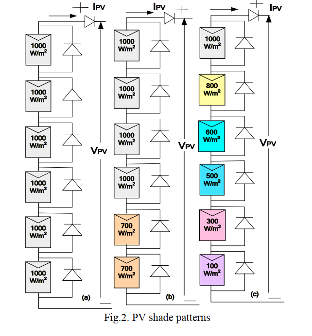 and here are the P-V curves for the above 3 examples 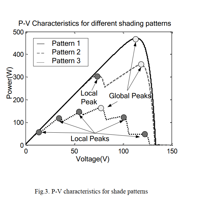 wronger than a phone book full of wrong phone numbers |
||||
| poida Guru Joined: 02/02/2017 Location: AustraliaPosts: 1478 |
Today I have connected board#2 to the East facing solar array. Weather is rain and some bright clouds but mainly rain. The code is the usual, a periodic scan for max power point, then run for a minute tracking around that point. here is the pwm during tracking, scan then back to tracking. https://youtu.be/Gh8SCeYtEPk Below is a graph of a certain time this morning when the sun nearly broke through. Peak power was about 1500W. Power INPUT is Orange, divided by 10 Blue is Volts IN Red is Amps OUT Green is Amps IN The x axis is 500 points wide, 1 second per point. 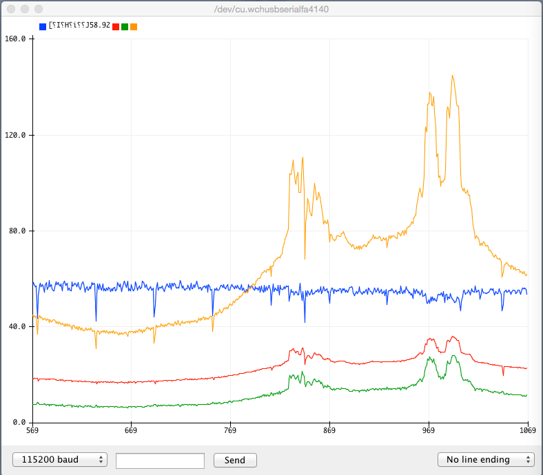 You can see a periodic short dip in output power. This is when the max power scan occurs. It is satisfying to see that after max power is determined, it is quite close to the power that was tracked just prior to the scan. It means the MPPT tracking is working well. The bucket of water (that holds the 1 Ohm load resistor) has nearly come to the boil https://youtu.be/H2wleS350hA Edited 2020-05-02 13:54 by poida wronger than a phone book full of wrong phone numbers |
||||
| Warpspeed Guru Joined: 09/08/2007 Location: AustraliaPosts: 4406 |
Really crappy weather like this is an excellent test for it. That is all looking really good. Cheers, �Tony. |
||||
| nickskethisniks Guru Joined: 17/10/2017 Location: BelgiumPosts: 478 |
I use an Re-1215, it should be one voltage, 12V is enough, even 10V will do. I have a s*load of certain components that are not allways the right fit, but it should safe me money, not allways. Btw, it has the same footprint then for example a recom R05B15 and it has - an +15V outputs. So you guys had a bad day huhm? I made a record with that powerpcb yesterday: 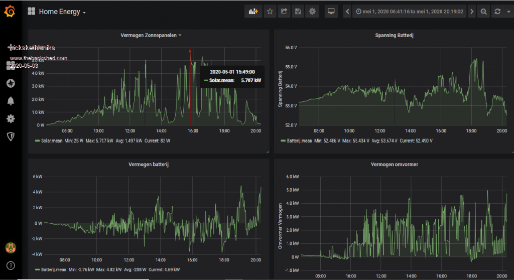 I don't consume that much energy btw, but I activate a heating element in my heat storage tank (3kW) as soon the battery voltage is 54V. The heat is used to warm the bathroom and the small office of my wife, they both have floorheating. So 5700W! that's more then 100Amps pumping in the battery (load)!  � �(btw there is a small gridtie inverter coupled to the ozz inverter) Edited 2020-05-03 05:22 by nickskethisniks |
||||
renewableMark Guru Joined: 09/12/2017 Location: AustraliaPosts: 1679 |
Looks like you are going well mate. Is there any benefit on placing mppt on 2s panels? Half my roof is 2s other half is 3s. Dunno how, but my system managed to capture 11 kwhr for the day, pretty good for such a bad day. Cheers Caveman Mark Off grid eastern Melb |
||||
| nickskethisniks Guru Joined: 17/10/2017 Location: BelgiumPosts: 478 |
Let's make it simple: In theory Yes, I say there are 2 extreme cases in my setup, empty battery 48V, full battery 56V. If I take 62V as mppt voltage. Gain @ 48V --> 62/48= 1,3 --> 30% Gain @ 56V --> 62/56= 1,1 --> 10% There are some losses, but they are also in another controller. And it depends, in my situation it doesn't make sence except in winter were I need all the energy I can get out my Array, the rest of the year I have to much energy. Edited 2020-05-03 14:07 by nickskethisniks |
||||
| ryanm Senior Member Joined: 25/09/2015 Location: AustraliaPosts: 203 |
So are you pretty happy with the circuit design poida? Just software from here on out? Pretty keen to get some parts on the way for my own. |
||||
| renewableMark Guru Joined: 09/12/2017 Location: AustraliaPosts: 1679 |
Well in winter even 10% extra is a big bonus. Cheers Caveman Mark Off grid eastern Melb |
||||
| poida Guru Joined: 02/02/2017 Location: AustraliaPosts: 1478 |
The hardware design is firming up to a design I can trust. I want to run a few things past Nicks.. first. It's his PCB. So far I have not broken either board and I have had some rather poorly performing code running things too. The bad thing the code does is go from 30% PWM to zero in one step. That sort of thing. No problem when this happens even under 1500W loads. wronger than a phone book full of wrong phone numbers |
||||
| nickskethisniks Guru Joined: 17/10/2017 Location: BelgiumPosts: 478 |
I'm sure the hardware can be improved, I would wait a bit until Poida has finished his tests. They are very informative and will only contribute to the reliability of the final design. Since I now have an array further away from the house I think I'm getting interest in a higher input voltage model. Anyway, the design is open for use or copy by others. I�m happy to make adjustments and maybe design a controller board. |
||||
| poida Guru Joined: 02/02/2017 Location: AustraliaPosts: 1478 |
Just a detail test: I wanted to see more accurately the difference between the 2 MOSFET types I bought. There was a hint that one board ran warmer than other other, and the warmer one was the IRFP4321 board. The FDH055N15A board always seemed to run cooler but it had a much bigger heat sink. So I fitted identical heat sinks to both boards and ran them for 10 minutes at 1850W. Both boards increased in temp (measured at about the same spot near a MOSFET) by 10 degC. Both inductor windings increased 20 degC and the ferrite cores about 10 C. Room temperature was about 20 C. I think the design is capable of extended periods at 2kW. So that's that. Time to work on the PCB to make a few small changes. Once that is done and checked by Nick I will feel confident to publish it here. The PCB work will happen while I am at work, there is a LOT of spare time for me when I am there. Also while at work I will write the beginnings of the firmware. I am looking forward to the coming weeks for this project, there will be some progress. wronger than a phone book full of wrong phone numbers |
||||
| The Back Shed's forum code is written, and hosted, in Australia. | © JAQ Software 2026 |
