Notice. New forum software under development. It's going to miss a few functions and look a bit ugly for a while, but I'm working on it full time now as the old forum was too unstable. Couple days, all good. If you notice any issues, please contact me.
poida Guru Joined: 02/02/2017 Location: AustraliaPosts: 1432
Posted: 07:20am 24 Mar 2020
Copy link to clipboard
Print this post
I am a strong believer in making your own inverters. The benefit is you can fix the damnned thing when it smokes. No need to return to the manufacturer at your cost including freight or postage. I had a Victron 3kW inverter. It cost me $2,700 AU and lasted 25 months. Warranty is 24 months. So that made me angry. Anger is an energy..
Time to make a MPPT of a useful size and (limited) function. And when it dies, I can fix it.
I use at the moment 2 charge controllers. I have 3kW panels facing North and another 3kW panels facing East. The North facing array is 3 in series x 4 giving about 105V open circuit. This goes to the Morningstar 60A MPPT controller. The East facing array is 2 in series x 6 going to a Morningstar 60A PWM controller. (2 in series is quite close to battery voltage and I am happy with the results)
Prices for the controllers (with $1 AU = $0.55 US) are: MPPT 60A $1122 PWM 60A $425 That's a lot of fun tickets. And - get this - you can blow up the MPPT controller just by enabling battery voltage when the device still has a large voltage stored in it's caps. Do not, ever, use the modbus command to reset. You will blow it. I am so tired of fragile and expensive devices we depend upon for our solar power systems.
The boards cost $100 AU for 5 boards plus about $100 for main components for 2 boards. I have a lot of 560uF 450V caps from dead grid tie inverters so I will use them. It may be that it is not enough capacitance. We will find out.
Specs: Input voltage: up to 150V Output voltage: 55V (i.e. a 48 V lead acid battery) Output current: 45A, nominal. Probably handle more but we will see. Home built with easy to source parts, simple construction, no bells and whistles, just get the current into the battery and don't over charge it for Dog's sake. PWM freq: 20KHz (due to the size of the inductor I have spare) control: Arduino nano. We all give a collective groan but I don't care. Open source project?: of course. One microcontroller, simple with low parts count. Heat sink: the biggest thing you have laying in the shed. efficiency: the buck converter will get maybe 90% at full load, 93% at low outputs. MPPT efficiency: near enough. The code will search for max power once a minute. Then run the standard peak finding algorithm used by all and his dog. Interface: LCD maybe, only if it does not upset PWM function.
code outline: ignore battery temperature. Charge to a conservative voltage. No float function. In my case it will be 55V. Find max power and send it to the battery if voltage is less than 55V. Limit output current to 45A. If at 55V, just maintain it there. Show some useful info on LCD if possible. Be aware of no solar voltage. Be aware of no battery connection. Do not over charge. Later if people want add temperature compensated charge voltages.
Nick (nickskethisniks) has kindly given me the design file for his solar buck converter. I have ordered 5 boards, 2 oz copper, and ordered some parts as needed. These arrive in 5 or so days.
Time to start coding. I have a test setup on the bench, just a buck converter with input volts, output volts and output current sensed. This is enough to start fleshing out some code.
In time nickskethisniks or me will publish the PCB files. I want to ensure the PCB has no problems first.
(by the way, the nanoverter/madness 6kW powerboard inverter I built is running well. I started using it back in early September 2019. So it seems I have found a long lived inverter design and will stick with it. And I know how to repair it too. This is a most pleasant feeling - to be able to fix expensive things yourself.)wronger than a phone book full of wrong phone numbers
Davo99 Guru Joined: 03/06/2019 Location: AustraliaPosts: 1584
Posted: 09:25am 24 Mar 2020
Copy link to clipboard
Print this post
I'll be very interested to see what you come up with using the Nano.
I have been playing with one a bit as a pulse generator for a direct water heater. Seems to me it would be very simple to code one up to sense the high and low voltage from a panel -IF- you knew how.
Sounds like there may be some parts of your design I can learn from so would be interested to see what you come up with.
BTW, what's wrong with Nanos?
Revlac Guru Joined: 31/12/2016 Location: AustraliaPosts: 1153
Posted: 01:18pm 24 Mar 2020
Copy link to clipboard
Print this post
Definitely agree that build it your self and be able to repair if necessary is the best way to go. Keep it simple, optional. Edited 2020-03-24 23:19 by RevlacCheers Aaron Off The Grid
renewableMark Guru Joined: 09/12/2017 Location: AustraliaPosts: 1678
Posted: 08:27am 25 Mar 2020
Copy link to clipboard
Print this post
The fangpusen 80A one I got for $500 runs nicely, it's a rip off from the outback. But when it goes pop, I won't be able to fix it. And I don't like it's layout, how the heat builds up in the top, totally sh*t design. Simply built/designed to go pop at some point.
Diy open source is fantastic, being able to harness the sun should be made as easy as possible.
Fantastic to see clever people make that happen.
Yell out if you need any bits, plenty of spares floating around here. I have some inductors from various things you may find handy.Cheers Caveman Mark Off grid eastern Melb
Warpspeed Guru Joined: 09/08/2007 Location: AustraliaPosts: 4406
Posted: 08:41pm 25 Mar 2020
Copy link to clipboard
Print this post
Have to agree with Peter, home brewing is definitely the way to go.
There will usually be big cost savings initially, and you can always have a spare tested circuit board ready to go, and a few spare mosfets on hand. If Murphy strikes, it should be dead easy to get going again fairly quickly.
Its also practical to build in all the exact features you want, and not skimp on things like decent heat sinks.Cheers, �Tony.
kentfielddude Regular Member Joined: 09/05/2019 Location: United StatesPosts: 89
Posted: 03:01am 26 Mar 2020
Copy link to clipboard
Print this post
The problem with home brewing is that your stuff isn't ETL or UL listed.
Davo99 Guru Joined: 03/06/2019 Location: AustraliaPosts: 1584
Posted: 10:40am 26 Mar 2020
Copy link to clipboard
Print this post
To many, that is not at all the concern it is to some others.
Regional differences make that quite a pre occupation to some where as to others whom know what they have built, it's barely a passing thought if at all.
Here at least, if you have a home brew appliance and you have a fire because because the store bought clock was faulty, they can't point to something unrelated and say that's not compliant so we aren't covering you for anything.
If your creation causes the fire, different thing. Insurance can and probably will walk away. Many are happy with that arrangement and to take responsibility for their own handy work.
Most mass produced things are made as cheaply as possible. Someone building something for themselves has a vested interest in it and are far more likely to ensure it's built to a higher standard than the bare minimum acceptable in a commercial product.
Seems to be one of those things that a lot of unfounded fear mongering and internet wives tales are based on though.
I can't wait to see the progress of this wonderful project! Can I ask for it to be one-sided? It makes it so much simpler for those who want to corrode the board with iron perchloride at home! Edited 2020-03-29 12:22 by hugocamaras
poida Guru Joined: 02/02/2017 Location: AustraliaPosts: 1432
Posted: 02:39am 29 Mar 2020
Copy link to clipboard
Print this post
Hugo, I ordered 5 boards. I will need 2 only so I can send you one if you like. But first I need to get a few things done.
The boards are arriving soon. I have bought the SMD resistors and caps, MOSFETs and diodes. I have enough DC bulk capacitors. I have fleshed out the code which has not been tested in any way.
I need to be able to simulate a solar panel. How? No idea actually. I have some linear bench power supplies that permit constant voltage and/or constant current control. I think I am going to use them. Maybe have one with 5A max limit, and 30V output. Have other 1A max and 45V output. Put them both in parallel. This will give a clear peak power of 6A at 30V, dropping very quickly to 1A at 31V.
I have a nice buck converter with input and output voltage and current sensing. Maybe with a bit of software I could make it provide 5A for output volts from 5 to 30V and reduce amps to zero by 35V output. This would simulate well a 5A 30V (150W panel).
And then I need to simulate a battery. I have some batteries but they are charged up. I am thinking of a microcontroller based DC load. The code will apply a constant DC load for voltages up to 24V and reduce it to near zero at 27V. That will give the mppt charge function a workout.wronger than a phone book full of wrong phone numbers
poida Guru Joined: 02/02/2017 Location: AustraliaPosts: 1432
Posted: 01:56am 30 Mar 2020
Copy link to clipboard
Print this post
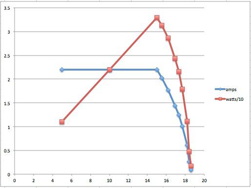
I have a simulation of a solar panel working well. It uses the buck converter running some custom code. The code runs in constant current mode, but with a twist. It is CC from 0 to 15V output, and then when the output volts rise from 15 to 18V, the output current is reduced proportionally.
This gives the sort of power verses voltage curve I need to test MPPT code.
The data is from the constant DC load I built years ago. I dial up a current and observe the voltage...
which looks like this when graphed. X axis is volts, Y is amps (and watts/10)
Beaut. Now I have something to test the MPPT buck converter against. If my MPPT code can't find that peak then something is very wrong.wronger than a phone book full of wrong phone numbers
BenandAmber Guru Joined: 16/02/2019 Location: United StatesPosts: 961
Posted: 09:34am 30 Mar 2020
Copy link to clipboard
Print this post
this new project sounds really cool poida
Sounds like u want to know and perfect every part of your system
Look forward to reading all about it
Please post pics anytime you get a chance
God bless you and all the other good people of Australia!!!!be warned i am good parrot but Dumber than a box of rocks
Hello Poida! Yes, I would like you to send me a board.
nickskethisniks Guru Joined: 17/10/2017 Location: BelgiumPosts: 462
Posted: 07:50pm 30 Mar 2020
Copy link to clipboard
Print this post
Poida, I would be happy to test your code on my solar controller if you want. :p
I will be following this topic with great interest, last weekend I did the winding of my 3 inductors. One step closer of hanging the controller against the wall.
I will be happy to help you anyway I can.
wiseguy Guru Joined: 21/06/2018 Location: AustraliaPosts: 1206
Posted: 10:28pm 30 Mar 2020
Copy link to clipboard
Print this post
Their is essentially no difference between the power stage of half (one leg) of an inverter and the power stage of a buck PWM used for MPPT. However their is quite a difference when returning inductor energy during the PWM off time.between a synchronous PWM buck and a non synchronous PWM buck (flywheel diode).
Efficiency should rise from ~ 90% up to >95% and hopefully closer to 97+%. The Power stage I am using for my inverter with the cross coupled LED/Opto drive that Warpspeed has advocated for some time, does work a treat. With no changes to my PCBs I can either have a 1 x 8 parallel Mosfet PWM controller that should be good for output currents to 100+A or by cutting a couple of tracks 2 channels of 50+A that could be applied to 2 different input strings combining their outputs to a common battery. �Their is a large range of Mosfets to choose from in the 100 - 150V range with sub 10mOhm on resistance down to ~ 3mOhms depending on your budget and acceptable losses.
Using the HY5110 that Ben first posted on here with the power PCB configured as 8 in parallel would yield losses of 2.6W at 100Amps standing, so switching could be ~ 5W total loss for strings under 100V @100A out. ($3 - $5ea on Ali Express)
Using a FDH055N15A configured as 8 in parallel would yield losses of ~7.5W at 100Amps standing so switching could be ~ 15W total loss for strings >100V but < 150V @100A out. ($7.30 - $8ea on Digikey)
Assume a switching rate of 20kHz, a good starting point for experimenting would be as below.
For strings of Vin 60 - 100V & Vout 55V using 8 x 100V Mosfets in Parallel could either use a common larger choke of ~ 30uH �or 2 smaller chokes ~60uH.
For strings of Vin 100 - 150V & Vout 55V using 8 x 150V Mosfets in Parallel could either use a common larger choke of ~ 45uH �or 2 smaller chokes ~90uH.
Using the topology I adopted, galvanically isolates the analog section from the Power section using isolated supplies and opto coupling the drive waveforms from the nano. Edited 2020-03-31 08:32 by wiseguyIf at first you dont succeed, I suggest you avoid sky diving.... Cheers Mike
ryanm Senior Member Joined: 25/09/2015 Location: AustraliaPosts: 203
Posted: 12:17am 31 Mar 2020
Copy link to clipboard
Print this post
Hi Poida,
I'm very interested in your board. Assuming it works I'll definitely be building one. Been looking for an open source MPPT design for a while now. If you need some real world testing for your code I'm quite happy to purchase a board off you and give it a try. I've got a couple of different panel voltages and batteries laying around. Also experience with Arduino programming and all the associated gear.
Edit: Note that I don't have anywhere near enough spare gear at the moment to drive it at 150A.
Ryan. Edited 2020-03-31 10:19 by ryanm
wiseguy Guru Joined: 21/06/2018 Location: AustraliaPosts: 1206
Posted: 06:04am 31 Mar 2020
Copy link to clipboard
Print this post
Sorry Poida I missed 2 places 1 above the spec & 1 below where you have already ordered 5 x PCBs. Note to self: do not read too hastily & before my first coffee.
When I skimmed the subject I thought the Spec was also aimed at hardware & a suitable topology selection - I know you will soon sort out the software.
When the software is ready I look forward to applying it to my hardware to try out.
Can I confirm that your MPPT scheme assumes VPanel is higher then VBatt so boost is not required ?If at first you dont succeed, I suggest you avoid sky diving.... Cheers Mike
Warpspeed Guru Joined: 09/08/2007 Location: AustraliaPosts: 4406
Posted: 07:54am 31 Mar 2020
Copy link to clipboard
Print this post
You need a variable voltage dc bench power supply and a series resistor of your choice. Couple up your buck converter to that along with some type of convenient low impedance load to dissipate the anticipated power.
You will be drawing maximum power from the source when you pull the voltage down to exactly half of what it is unloaded.
By changing the value of your series resistor over a wide range, if the software "brain" always loads it down to half the open circuit source voltage, with a combination of different source voltages and series test resistor values, your algorithm works fine at finding max power transfer.
The idea is that max power transfer always occurs when a load impedance is perfectly matched to the source impedance. That will always pull the voltage down to exactly half, because its really just two equal resistors in series, source and load.
The source impedance will be your series test resistor, plus whatever internal impedance the dc power supply has. �The load impedance will be your buck converter and actual final dissipative load in series with it.
Turn on the power and watch your software creep towards loading down the source voltage to EXACTLY half the open circuit voltage. That operating point equates with max power transfer.
Now solar panels are odd things, they are very non linear source, a charging battery makes up a complex non linear load as well. If your algorithm can truly seek out and lock onto the power peak, it will aso work on something much more predictable such as a voltage source of known impedance.
So you really don't need to duplicate crazy solar panels and batteries for a valid test of your software. Edited 2020-03-31 18:11 by WarpspeedCheers, �Tony.
poida Guru Joined: 02/02/2017 Location: AustraliaPosts: 1432
Posted: 08:05am 31 Mar 2020
Copy link to clipboard
Print this post
thanks for the offer of help Ryan. I think it likely I will want you to help in testing. There goes spare board #2. One left.
I think my specs are up to 150V IN, 45 A out, 48V lead acid battery as the load. I think it's not really important that we test immediately at max power/voltage. I want to start with baby steps. I am not an EE (Electronics Engineer) tho some here on the forum are.
First things first. The boards are in transit from JCLPCB. The main components are supposedly here at home already according to RS-Components. But they are not.
This is to be a simple and reproducible project. We just need a decent but not optimal MPPT charger for 48V lead acid batteries. (one change to a #define is all that's needed to change to different battery chemistries)wronger than a phone book full of wrong phone numbers
poida Guru Joined: 02/02/2017 Location: AustraliaPosts: 1432
Posted: 08:19am 31 Mar 2020
Copy link to clipboard
Print this post
Mike, for sure the idea is to take a solar array of voltage well bigger than the battery. I view a reasonable design of a solar array/CC/inverter/battery to have the solar array about 50 to 100% larger voltage than the battery. Why? The high voltage let's you use thinner wire from array to CC. In my case the cable run is 30 meters or more. I do not like I2R losses. I can live with marginal Rds(on) losses due to high voltage MOSFET choices.
The reason for MPPT is to produce a design that can take any and all used and abused panels we can buy for small$. Chances are the panels are not optimal for a simple 2 in series PWM setup (for eaxample..) MPPT will take all voltages within reason and convert to useful charge outputs.
The amount of energy available during early morning and late evening is small and I do not care for special conditions where MPPT is dropped in favor of straight through connection of panel array to battery. The code will run MPPT and the DC-DC converter when power IN is not enough.
The code will look for lower Vin compared to Vbattery and turn off. I also want it to look for no battery load and turn off. It would be nice if it was idiot proof and just survived all attempts to kill it. Edited 2020-03-31 18:19 by poidawronger than a phone book full of wrong phone numbers
renewableMark Guru Joined: 09/12/2017 Location: AustraliaPosts: 1678
Posted: 03:25am 01 Apr 2020
Copy link to clipboard
Print this post
LOL, bet I could find a way to kill it.
I'de love to have a board, but will let someone else grab the last one as I will most likely not get onto it for a while.
Yell out if you need any bits.Cheers Caveman Mark Off grid eastern Melb
Page 1 of 50
Print this page
The Back Shed's forum code is written, and hosted, in Australia.