Notice. New forum software under development. It's going to miss a few functions and look a bit ugly for a while, but I'm working on it full time now as the old forum was too unstable. Couple days, all good. If you notice any issues, please contact me.
Solar Mike Guru Joined: 08/02/2015 Location: New ZealandPosts: 1220
Posted: 07:58pm 01 Apr 2019
Copy link to clipboard
Print this post
Agree the TL431 is a great device, there are about 30 of them in a tin on my bench somewhere... didn't use one as I would then require another device as the latch, where as I had already some small smd versions of the venerable LM393, and with a few extra resistors etc could use it as the over voltage trip and resettable latch in the single device; the TL431 would be more accurate, but that aspect not required in this instance.
Inrush current can be an issue, input limited here by the PV being a constant current source of 25 amps or so at the 155 Vmp being used here, so not worried about it. Connection to the battery will cause a splat charging up the output caps, when switched by the output breaker, cannot see any efficient way of managing that.
The current detection circuitry has too much latency to use it for limiting of inrush currents and as the device is not yet powered up at the instance of connection couldn't be used anyway.
Cheers Mike
BenandAmber Guru Joined: 16/02/2019 Location: United StatesPosts: 961
Posted: 09:13pm 01 Apr 2019
Copy link to clipboard
Print this post
I have high hopes that at the end of testing this design
you will make it kind of monkey see monkey do
so some of us less experience members can build learn and benefit from your hard work and wisdom
Thanks for your time and hard workbe warned i am good parrot but Dumber than a box of rocks
Solar Mike Guru Joined: 08/02/2015 Location: New ZealandPosts: 1220
Posted: 06:21am 02 Apr 2019
Copy link to clipboard
Print this post
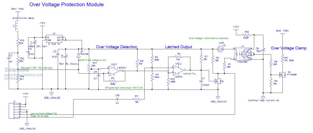
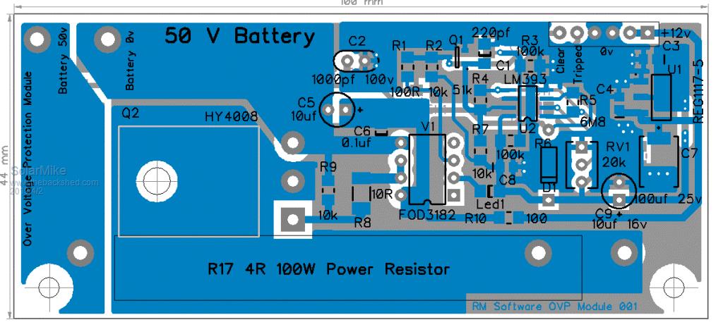
OK, have completed the layout for the Over voltage protection part, made as a plugin board 100mm x 44mm that sits atop the main power board above the mosfets and pickups the main power tracks etc from the mother board.
Have fitted a 100w 4 ohm resistor and a mosfet to sink any current from the capacitors. Obviously we don't want this thing to activate during normal operation as something will melt, can test fully it by not plugging in the opto-coupler.
One issue I have is its manually setup (RV1), so the charger cannot automatically set it for different voltage battery banks, can live with this, never use less than 48v anyway.
Due to the generic nature of the board, will use it in other projects, can get on with the changes to the main power board now... many alterations.
Cheers Mike
Solar Mike Guru Joined: 08/02/2015 Location: New ZealandPosts: 1220
Posted: 10:41am 03 Apr 2019
Copy link to clipboard
Print this post
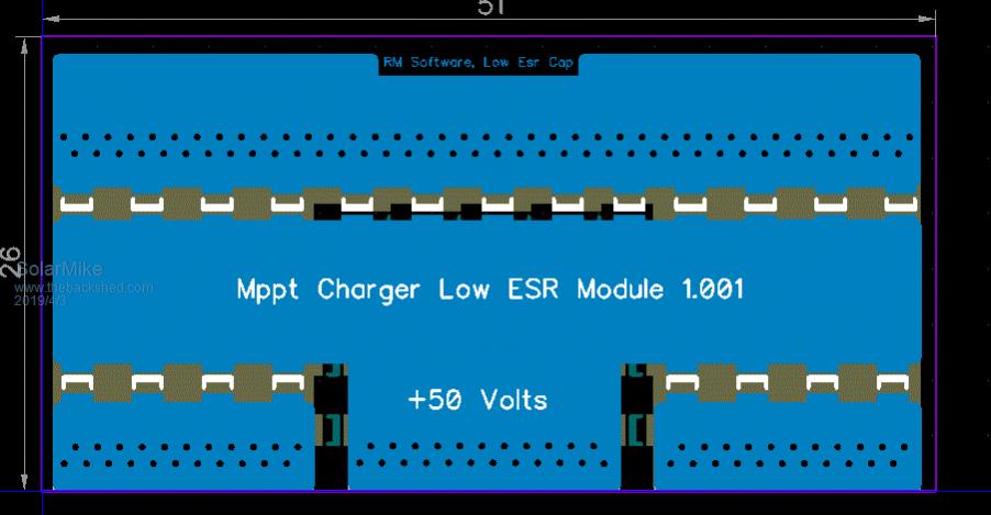
Decided to add a small pcb containing 30 or so 1uf 250v ceramic caps parallel with the main output electro's. Originally they were to be mounted under the main pcb in a line across the power rails. This pcb sits between the main caps and soldered to the top tracks.
Reason for doing this is its not unknown for these types of cap to go short circuit, even if correctly rated, being effectively across the battery, will draw lots of current carbonizing the pcb and effectively destroying the board in the process. Placing them on a separate pcb makes repair easier.
azhaque Senior Member Joined: 21/02/2017 Location: PakistanPosts: 131
Posted: 09:55am 06 Apr 2019
Copy link to clipboard
Print this post
Mike,
Need your help in relating and understanding the PCB image to the above image.
On the PCB I can't locate the MOSFET that will play the role of the PV isolator. Have you abandoned having an isolator MOSFET after adding in the ACS770? Would the ACS detect reverse current and shut down the system after sunset, thus making the isolator redundant?
Thanks and regards
azhaque
Solar Mike Guru Joined: 08/02/2015 Location: New ZealandPosts: 1220
Posted: 10:49am 06 Apr 2019
Copy link to clipboard
Print this post
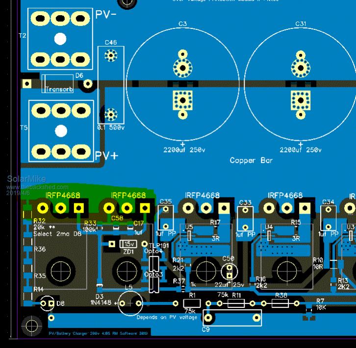
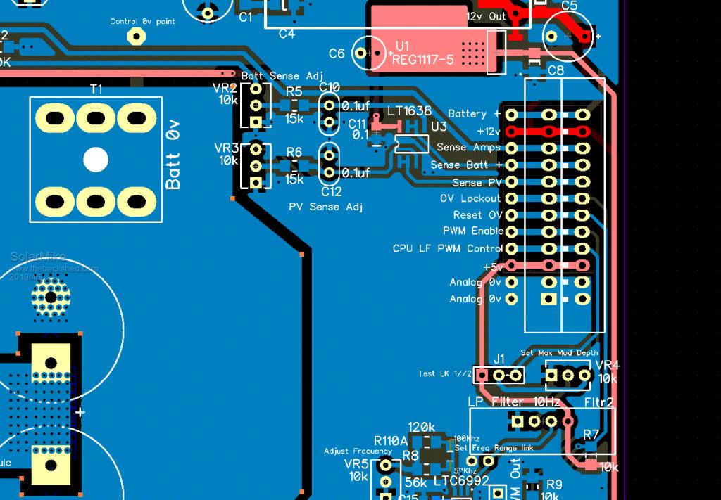
No this part of the circuit hasn't changed, the 2 parallel IRFP4668 mosfets are switched by opto-couplers that output a DC voltage, see the highlighted (yellow).
The whole pcb is being re-designed; the PWM driver and associated components have been moved from the CPU board to the power unit, to better allow easier connection for other CPU types. see part pcb below.
The ACS770 output is passed to the CPU board where any decisions are made to shut down or isolate the PV array from battery.
Cheers Mike
BenandAmber Guru Joined: 16/02/2019 Location: United StatesPosts: 961
Posted: 07:39pm 06 Apr 2019
Copy link to clipboard
Print this post
Solar Mike I haven't got a chance to read this post yet as soon as I get a chance I will read it from beginning to end
I just wanted to jump on here long enough tell you thank you so much for your very very hard work
this is going to benefit so many people when you're finished thank yoube warned i am good parrot but Dumber than a box of rocks
azhaque Senior Member Joined: 21/02/2017 Location: PakistanPosts: 131
Posted: 03:14am 07 Apr 2019
Copy link to clipboard
Print this post
Greetings, Peace and many thanks for the update, Mike.
When doing the uC PCB, please do incorporate an SD Card and an RTC. These will help to do datalogging.
azhaque
Solar Mike Guru Joined: 08/02/2015 Location: New ZealandPosts: 1220
Posted: 05:54am 07 Apr 2019
Copy link to clipboard
Print this post
To get this thing running initially and debugged, will be using a very basic CPU card using a 14 pin PIC CPU. The only fancy thing on it will be an LCD display, I will leave it to others to build anything more sophisticated.
Solar Mike Guru Joined: 08/02/2015 Location: New ZealandPosts: 1220
Posted: 11:46am 09 Apr 2019
Copy link to clipboard
Print this post
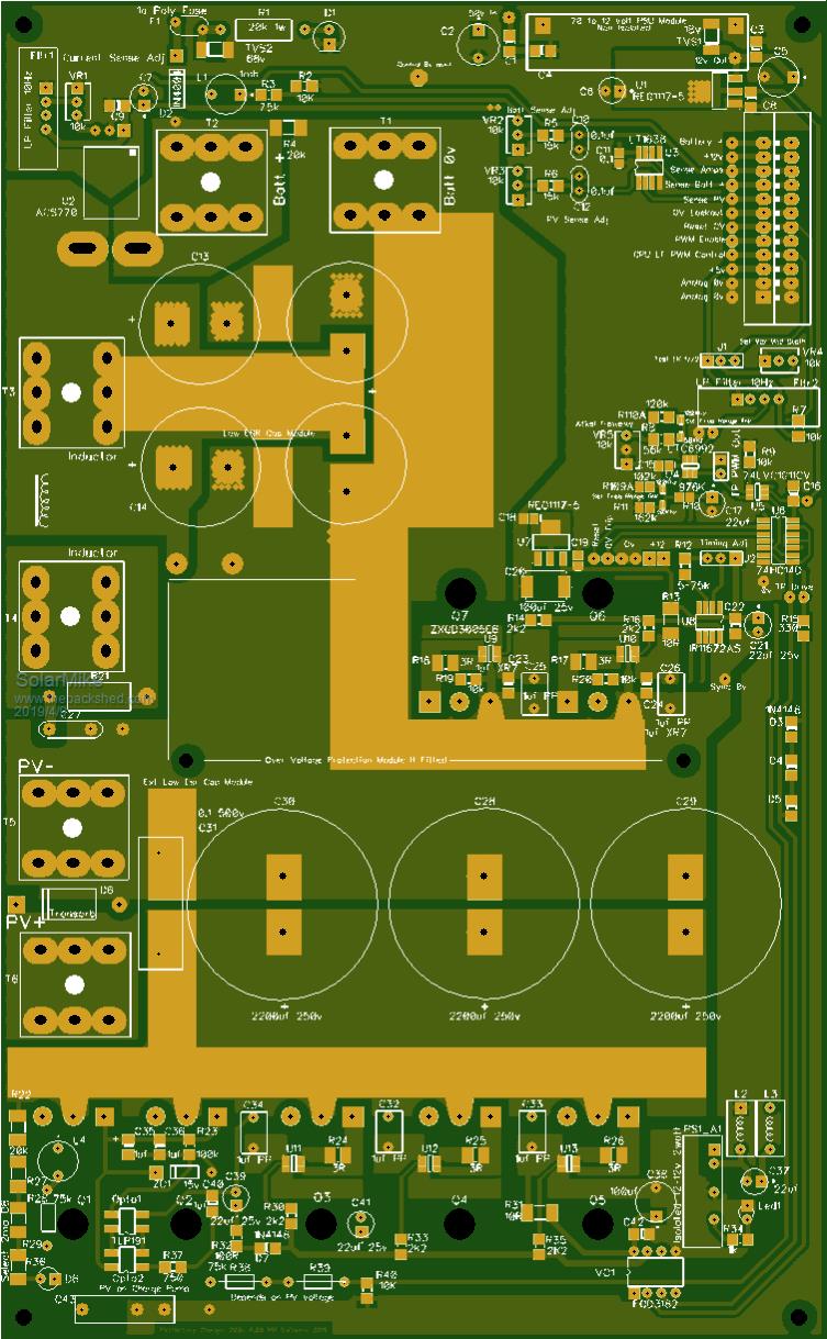
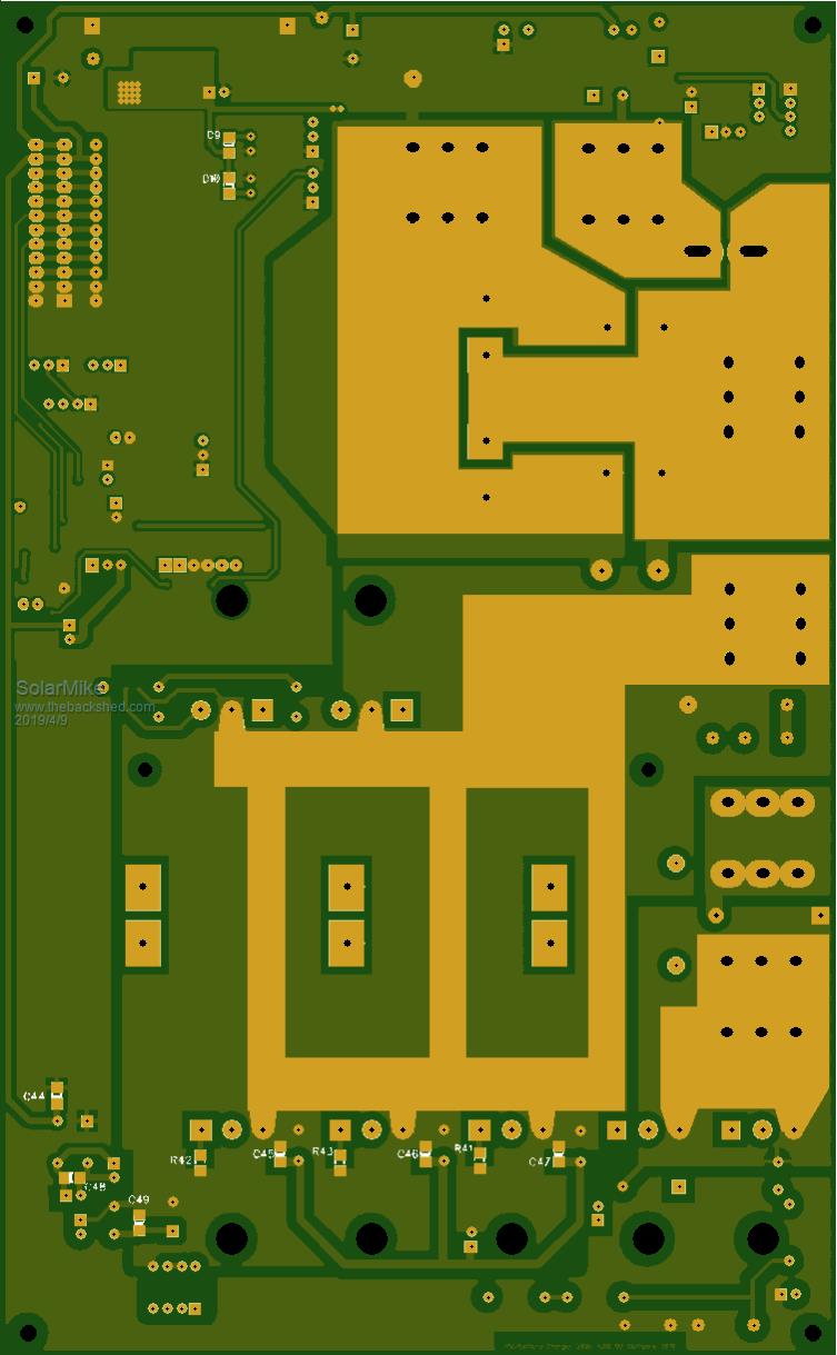
Onward, its been a bit of work to modify the main power board, have added a HF modulator and associated components to easily allow full mppt control by an add on CPU board. Ready to send off to get test boards. Final size is 243 x 150mm, have widened some of the main current tracks to allow use of 1oz copper.
Along the line, I laid my hand on dead outback 60a flexmax , I want to clone the circuit layout and see how those guys switch the two bucks with logic gates .. will post updates on proces .. cheers Ghost 👻.
azhaque Senior Member Joined: 21/02/2017 Location: PakistanPosts: 131
Posted: 01:50am 23 Apr 2019
Copy link to clipboard
Print this post
Mike,
Would it be possible to connect two or more of these controllers to a single battery, to increase current capacity.
Regards azhaque
Solar Mike Guru Joined: 08/02/2015 Location: New ZealandPosts: 1220
Posted: 02:44am 23 Apr 2019
Copy link to clipboard
Print this post
Yes, I have a couple of smaller test devices connected to the same battery, however they each have their own isolated PV array. One always seems to switch to float etc earlier than the other, prob because of differing voltage drops in cables and circuit breakers etc. I have not added remote battery voltage sense yet. There is no system here to keep them in track, ie master\slave, would be easy to do, its just software.
No, if sharing the same PV source, would require cycle by cycle current limiting, ie a very fast process, this is not in the design brief.
I would quite like to build a multi-phase controller, so that smaller inductors could be used, this would also allow plugging in extra modules for added current capacity..... way down the track.
PCB's for test boards are in transit from China, so waiting......
Cheers Mike
azhaque Senior Member Joined: 21/02/2017 Location: PakistanPosts: 131
Posted: 05:44am 23 Apr 2019
Copy link to clipboard
Print this post
OK. I guess a circuit between the the o/p of the multiple CCs and the battery could perform such a function. Likely to be relatively simple with multiple ACS758 type of devices, monitoring the respective stream and either PWMing each stream to balance currents OR sending data to the mppt CC cpu using MODBUS to adjust their outputs.
Yessss!
azhaque
azhaque Senior Member Joined: 21/02/2017 Location: PakistanPosts: 131
Solar Mike Guru Joined: 08/02/2015 Location: New ZealandPosts: 1220
Posted: 07:13am 23 Apr 2019
Copy link to clipboard
Print this post
What sort of max charge currents and voltage are you expecting to use azhaque, that require parallel controllers.
Cheers Mike
azhaque Senior Member Joined: 21/02/2017 Location: PakistanPosts: 131
Posted: 08:48am 23 Apr 2019
Copy link to clipboard
Print this post
Oven 3KW thats 60 amps at 48vdc Aircon is another 50 amps Fridge and Deepfreezer 6 Amps Battery charging under bulk 30 Amps for now.
That brings the total to 140 Amps. Of course it would not practical to run the aircon and the oven simultaneously. So the range is from 40-100 amps at any one time.
I am off grid, so nothing to complement solar
azhaqueEdited by azhaque 2019-04-24
Solar Mike Guru Joined: 08/02/2015 Location: New ZealandPosts: 1220
Posted: 10:31am 23 Apr 2019
Copy link to clipboard
Print this post
See what you mean, whilst its possible to make a 150a mppt controller, the inductor starts getting very big, the cables from the panel array have to be large also, I^2R losses start adding up.
Much easier to have 2 or more controllers each with their own PV array, possibly orientated in different directions to better average out charge through the whole day; also mitigates risk should a single large device fail.
Will think about best way to allow a Master controller to assume control over the others.
Cheers Mike
Page 7 of 10
Print this page
The Back Shed's forum code is written, and hosted, in Australia.