
|
|
Forum Index : Electronics : Inverter building using Wiseguys Power board and the Nano drive board
| Author | Message | ||||
| KeepIS Guru Joined: 13/10/2014 Location: AustraliaPosts: 2210 |
For anyone interested in uploading HEX code files to the Nano, user -dex- pointed me to an even simpler program then the one I posted, it's an older program and a really simple interface, which saved me writing one once I saw this. Again, using a version of the program up-loader that comes with the Arduino IDE, this version however - had no trouble with the last 4 Nano boards I purchased, go figure. The program is called Xloader, I modified the Nano selection and it clearly gives you the selections for: Nano ATmega328 New BootLdr or Old BooLdr, both links are below. X loader with Nano select mod. Github download for Xloader Click on green "<> CODE" button and then download Zip. NANO:Inverter V 8.4ks - Linux AvrDude GUI script V4.1 |
||||
| KeepIS Guru Joined: 13/10/2014 Location: AustraliaPosts: 2210 |
I thought I would post the circuit for the DC input Peak reading meter with an extra output connection for the driving the Nano Controller via the Ext Trip Pin. The trip connection to the Controller is not really needed for general lower power usage, less then 4kW. But the meter itself is a very informative tool when mounted on the inverter for monitoring Peak DC input via the Hall effect Sensor or DSO socket. The Sensor can be mounted by itself and only used with a DSO for occasional inverter testing and monitoring of inverter DC currents. The sensor only needs 12v from the Nano to run. The Hall Sensor is a permanent part of my inverter. The Sensor is mounted so that +50V DC 0G cable from the Kilovac relay output passes through the Sensor and continues on to the Power board capacitor banks. The Hall effect Sensor I use is a 12v 500A unit and can easily read to over 750A. I used an tiny isolated supply on the original but not really needed, these small DC-DC modules are also used in the WG inverter Power board. 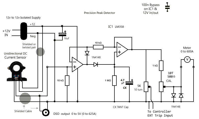 . Link to my Peak Current Meter information. I said in the old post that it was hard to calibrate, but turns out it's easy, if anyone is interested Hall Sensor Make sure to select the correct current rating and DC voltage if you purchase one. EDIT: I should have mentioned the option of substituting a LED bar-graph strip for the analogue Meter. . Edited 2024-05-23 08:41 by KeepIS NANO:Inverter V 8.4ks - Linux AvrDude GUI script V4.1 |
||||
| KeepIS Guru Joined: 13/10/2014 Location: AustraliaPosts: 2210 |
For anyone interested, a picture of the Peak DC current detector in the inverter, it's the small veroboard at the front of the shelf. Maybe I should ask Klaus if he ever made a PCB for his? The aluminum stand forms part of a ground plane for the Nano controller. The Nano board is mounted with a single plated copper post and 3 plastic posts, the metal post connects the aluminum plate to the ground plane mounting terminal built into the controller PCB. It's important to ensure that no other ground connections interfere with this - The PCB ground plane connections is not connected to the controller PCB ground. This setup makes a huge difference to inverter noise in the Controller board. The aluminum stand is connected by a very short heavy gauge cable to the Negative battery terminal. Terminal is just above the stand. As inverter noise extends way up in the RF spectrum, this lead must be as short a possible and of good quality thick copper cable. This was setup and confirmed with a 380Mhz bandwidth DSO. The Red cables either side of the stand run from the Power board SPWM outputs, they connect to two Chokes in the lower Toriod section via copper plates and through bolts. The Power board at the back of the controller section is seen protruding through a cutout in the rear of the cabinet, the power board is mounted to a huge heatsink and the heatsink and power board are easily removed as a single unit in a few minutes. FYI the Toriod is 200mm high, each choke is 100mm high. 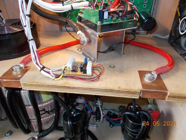 . Edited 2024-05-24 17:26 by KeepIS NANO:Inverter V 8.4ks - Linux AvrDude GUI script V4.1 |
||||
| -dex- Senior Member Joined: 11/01/2024 Location: PolandPosts: 104 |
The noise generated by the inverter is something I pay attention too. Currently, the inverter interferes very strongly with the entire band of my ham radio. wiseguy has prepared a place for a possible small capacitor for the gnd connection of the controller with chasis. It seems to me that your aluminum plate, at some distance from the gnd plane, creates some parasitic capacitance that probably does the same thing as the soldered capacitor. The question is why you connect it to the negative power rail and not to earth?  |
||||
| Murphy's friend Guru Joined: 04/10/2019 Location: AustraliaPosts: 678 |
Yes, he did  . Already sent one to Roger, if you want one too, I should have another spare to replace your veroboard special . Already sent one to Roger, if you want one too, I should have another spare to replace your veroboard special  . .It's a small PCB, doubled up with my inductance saturation tester PCB. They can be separated easily. |
||||
| KeepIS Guru Joined: 13/10/2014 Location: AustraliaPosts: 2210 |
Because I'm removing inverter induced RF from the Controller. This noise is on the board cables that run from or near the main inverter input power bus. I'm not trying to stop external radiated RFI from the inverter. So for this inverter noise, the Main battery NEG connection, either right at the Power board, or very close to it, as is my case, as an equally short NEG cable runs from the Power board NEG up to the main NEG bus connection, just above the controller. This is the RF earth for the Power bus. The earth plane is part of the PCB layers, yes the aluminum plate below it is also a screen for radiated RF from the toroid section below it. When measuring controller noise, I measure between the negative bus at the power board Neg connection, and various points on the Controller PCB, Nano pins, PSU in and out, etc. This was the most effective method I found for reducing Inverter switching noise from the Controller. RF radiation into my Ham rig is mainly from one of my Solar controllers, I'm sure that you shutdown all solar controllers when testing for RFI from the inverter, I have only 1 spike on the Amateur-R sections of the 40m band with the inverter. However that one solar regulator is a real problem when it's running, it's the same make and spec as the 4 older models, but obviously something is different, perhaps cost cutting from the Chinese manufacture in the later model? It puts RFI right across the band with some "20db over 9" wide spikes. Don't run a VFD, the lathe VFD kills the entire band with 40db over. I'm just to busy (or slow) to track it down at the moment  EDIT: BTW any earth connection as shown with a capacitor, always increased the RF noise on the controller board in my setup. . Edited 2024-05-24 18:02 by KeepIS NANO:Inverter V 8.4ks - Linux AvrDude GUI script V4.1 |
||||
| KeepIS Guru Joined: 13/10/2014 Location: AustraliaPosts: 2210 |
Sounds great Klaus, don't sweat it if you can't find one, but let me know if you do and I'll arrange something.  NANO:Inverter V 8.4ks - Linux AvrDude GUI script V4.1 |
||||
| KeepIS Guru Joined: 13/10/2014 Location: AustraliaPosts: 2210 |
The previous big post "05:57pm 24 May 2024" should read as follows: When measuring controller noise, I measure between the negative bus at the CONTROLLER board Neg connection, and various points on the Controller PCB, Nano pins, PSU in and out, etc. I had somehow enter "power" board instead of "CONTROLLER" board . Edited 2024-05-25 08:27 by KeepIS NANO:Inverter V 8.4ks - Linux AvrDude GUI script V4.1 |
||||
| KeepIS Guru Joined: 13/10/2014 Location: AustraliaPosts: 2210 |
Klaus, the board just arrived, this is a really nice PCB, it's moved to the front of the PCB row that I'm trying to get built - Thanks again for this. . NANO:Inverter V 8.4ks - Linux AvrDude GUI script V4.1 |
||||
| Murphy's friend Guru Joined: 04/10/2019 Location: AustraliaPosts: 678 |
Thanks Mike, I do my boards the old fashioned way, laid out by hand and with decent pads that could stand the odd unsoldering. Let me know if you have any questions, doubt it though . |
||||
| -dex- Senior Member Joined: 11/01/2024 Location: PolandPosts: 104 |
I'm still wondering if I really need this aluminum plate under the controller board. Have you performed any tests without this plate? Did the inverter controller become unstable without it? Edited 2024-06-05 18:45 by -dex- |
||||
| KeepIS Guru Joined: 13/10/2014 Location: AustraliaPosts: 2210 |
Yes, I tested without the aluminum plate, there was a Big measurable difference, I don't believe it was unstable - remember this was with the previous 8010 controller on the same Board design as this Nano. . NANO:Inverter V 8.4ks - Linux AvrDude GUI script V4.1 |
||||
| wiseguy Guru Joined: 21/06/2018 Location: AustraliaPosts: 1298 |
Mike, you mentioned that the brownout of the Nano is around 1.8V I read somewhere that there is a register value to set the brownout detection value. If the value can be set to a high level say 3 or 4 volts then operation should be halted when it gets to that threshold ? There is a linear regulator on Nano pin 30, so we could feed it from the 12V. There is also a reset pin on Pin3, so if the internal brownout detector is a no go, I am starting to lean towards a separate added 5V supervisor 3 pin device (TO92) on both the inverter and the LCD boards as a last resort. Dex is suggesting we use an A/D and trigger an scr etc on the 5V and it does not feel like the right approach as we might have simpler solutions available yet. Poida ! do you have any idea about brown out settings and whether it is normally enabled and if so what brownout value. Also for the LCD display, I am trying to avoid messy hardware changes and it would be great if it is just a software tweak setting to stop the Nano from operation below 3 or 4 bolts and way before 1.8V ? Edited 2024-06-06 01:36 by wiseguy If at first you dont succeed, I suggest you avoid sky diving.... Cheers Mike |
||||
| KeepIS Guru Joined: 13/10/2014 Location: AustraliaPosts: 2210 |
Raising the brown out value can often cause more issues, strange as it may seem. Simply program it without the bootloader. I have tested the Nano I/O pins under this induced condition - they are stable. I wanted to add this, code won't do anything once the Nano is at or below BOR, all the Nano is doing is seeing a reset, right as the voltage is around BOR, so it might try to start, see another reset, etc. I can confirm by test code, the Nano only managed to do one reset and part run, when down in that < 3v sawtooth waveform area. Keep in mind, that there is NO indication of any positive spiking of the Nano 5v supply (spiking above 5v) - this is why I am unconcerned with these conditions in my own inverter, Without a bootloader though That USB controller is unknown and likely glitching - no bootloader - then it can do nothing to the nano. . Edited 2024-06-06 08:57 by KeepIS NANO:Inverter V 8.4ks - Linux AvrDude GUI script V4.1 |
||||
| wiseguy Guru Joined: 21/06/2018 Location: AustraliaPosts: 1298 |
Have had a total rethink of the startup stragedy oops strategy. The main problem was caused by the slow shutdown introduced by the main capacitor bank and the regulators behaviour as the capacitors slowly drain & even recover briefly with the bad effects to both Nanos. So the proposed on/off 48V startup circuit is a 2 pronged approach that I believe will solve the problems with minimal work (card mods) involved. The new scheme stops the main capacitor bank from continuing to feed power to the control card when the on/off switch is set to off. Further the switch being set to "off" crowbars the 12V & 5V supplies to ground (be nice through a 1R-4R7 resistor) so the 5 & 12V supplies get a whoa camel moment (instantly stopped) so the control card and LCD 5V are instantly stopped. The card mods required is to leave off Q10 R27 R28 and C28 and on the card put a link where R27 & R28 were to short the previous "Stop" card connection to ground. Of course the off position of the switch could also be connected to a convenient ground nearby, it does not have to connect to the card ground but on the card is my recommendation. 1) Change the precharge resistor/diode & Contactor-feed wiring as per start up schematic. 2) Remove (or dont install) Q10, R27, R28 & C28. 3) fit 3 diodes and 1 resistor to card - easy using breadboard area (1 cut track). Edit: Maybe rethink the DB shorting the 12V to ground is not really needed & probably overkill. 4) instead of a link fit a connector and wires to J11 for a new run stop switch. To start the inverter it wont matter which position the run/stop switch is in. To stop the inverter though the run/stop switch should be set to stop first and then when the green led is not flashing now turn the on/off switch to off. If the inverter is on with the run/stop switch set to run, the auto shutdown on low battery and auto restart when battery voltage rises again is all unaffected. if the batteries get to ~7V with the on/off switch still set to on I think you have greater problems than Nano code corruption. Control Card Mods - only 1 track to cut (Note: the 48V is now switched to ground when on/off is set to off) 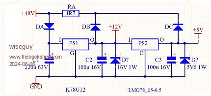 Start up wiring Mods. Auto Start Mod.pdf Sorry Mike this should have been posted I think in my thread so I will duplicate it there Edited 2024-06-06 11:48 by wiseguy If at first you dont succeed, I suggest you avoid sky diving.... Cheers Mike |
||||
| KeepIS Guru Joined: 13/10/2014 Location: AustraliaPosts: 2210 |
replied in other thread.NANO:Inverter V 8.4ks - Linux AvrDude GUI script V4.1 |
||||
| KeepIS Guru Joined: 13/10/2014 Location: AustraliaPosts: 2210 |
FYI, since were into brute force Across the LCD plug on the Controller, would likely be even better across the +5v output of the regulator module, that could be done without even removing the controller board, depending on the reg you use. The Capacitor is small as voltage requirement is 6V. I'll try it later - does not appear to bother the reg at all. Have not even had a chance to test the 12V output only - that should tell me which one is causing this. No Cap: 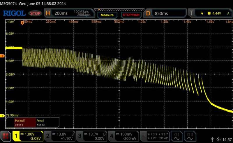 330uf: 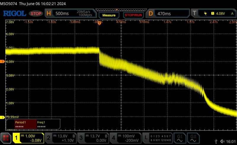 1000uf: 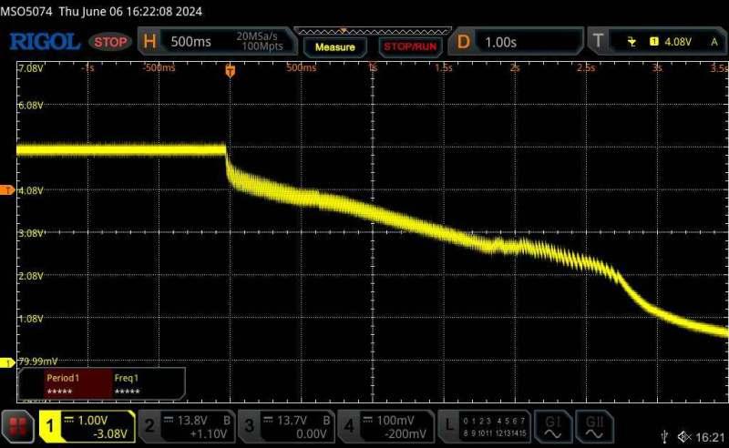 LEDs and screen just fade out normally. NANO:Inverter V 8.4ks - Linux AvrDude GUI script V4.1 |
||||
| KeepIS Guru Joined: 13/10/2014 Location: AustraliaPosts: 2210 |
FYI and just to finish the testing. Some better DSO captures, and proved it's the 5V regulator. This is the 12v rail with 1000uf. I didn't save the next capture but it shows the same bit of noise on the end of this one as it drops, it's coming back from the 5v regulator in the next pix, which has almost a 2vp-p saw-tooth around 90Hz. This is the 5v rail with no cap with the 12v rail as above. 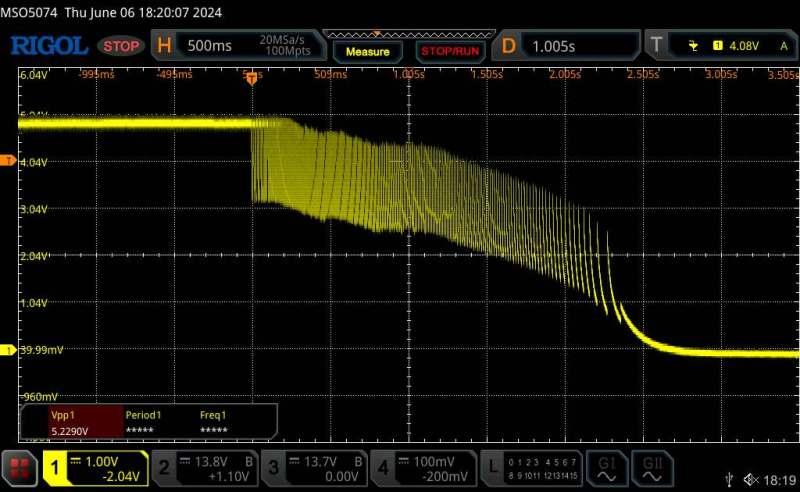 The 5v rail with a cap across the regulator output. 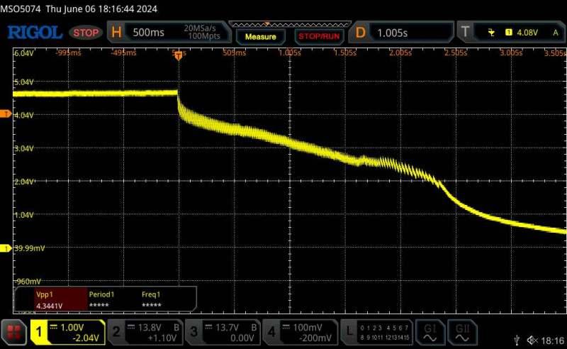 LCD and Power LED fade out nicely. Tomorrow I'll look at the Hardware mods with respect to the operation of my inverter. Things I find may have no relevance to other inverters builds, but it's worth looking into in case it offer an advantage I have overlooked. . NANO:Inverter V 8.4ks - Linux AvrDude GUI script V4.1 |
||||
Cobbler Newbie Joined: 25/01/2023 Location: AustraliaPosts: 14 |
In light of the above undesirable behaviour observed in some 5V switching regulators, I feel it is appropriate to interject and point out a pretty thorough online analysis that may be of interest to those looking at ordering the 5V MINI-360 regulator for their WG Inverter build. Unsurprisingly, the tests reveal concerning behaviours seen in at least some of the MINI-360 regulators sold online: Tested: MINI-360 (MP2307-based) “3A” Buck Converter Module https://goughlui.com/2018/07/04/tested-mini-360-mp2307-based-3a-buck-converter-module/ Unfortunately, the inexpensive GAPTEC LMO78_05-0.5 recommended in the WG39 Rev7 Nano Controller BOM appears to be out of stock at the major distributors I checked (DigiKey, Mouser, Element14 and JLCPCB), however a suitable alternative rated at 1A output is currently in stock at DigiKey: https://www.digikey.com.au/en/products/detail/monolithic-power-systems-inc/MEZD71201A-G/6823821 A thorough analysis of a 2A version of the above regulator has also been posted online: Tested: MPS mEZD71202A-G 6.5-24V to 5V/2A DC-DC Power Supply Module https://goughlui.com/2021/04/03/tested-mps-mezd71202a-g-6-5-24v-to-5v-2a-dc-dc-power-supply-module/ Cheers Michael |
||||
| KeepIS Guru Joined: 13/10/2014 Location: AustraliaPosts: 2210 |
Thanks for the update, yes I was about to post about the poor implementation / design of that 5v regulator, IMHO it is a POS. In the interest of keeping it simple and getting that 5v reg out of the way. I fitted a linear regulator 7805 - we have discussed this before - it is catered for in Wiseguys board design, available everywhere, local jaycar in AU. BTW extensive testing on the 12v regulator indicated no issues. The controller in the Inverter, there is noise on the 48V battery feed. This is the 5v rail, No LCD and the Controller NANO is not inserted. 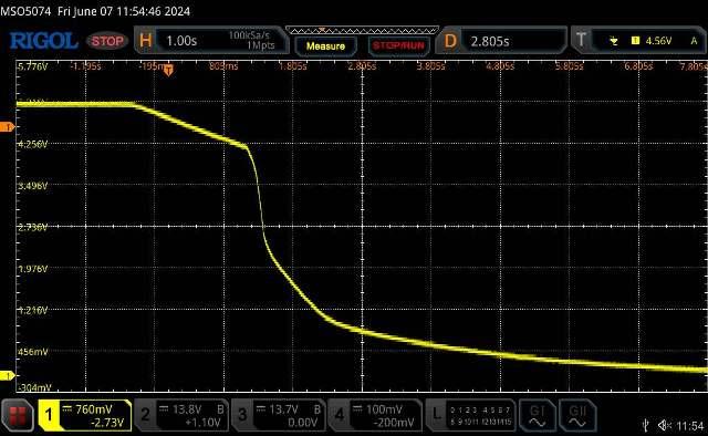 With the Nano inserted - there is a slight blip on the rail at 2.7v as the Nano power down. There may be something happening as the LCD backlight switches off on the now unregulated 5v rail and other 5v IC drop off? 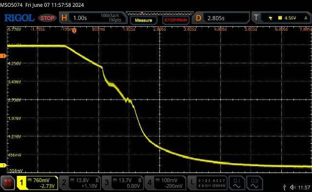 Finally, a small 6v 1000uf electrolytic across the LCD plug on the controller, a slight noise at 2.7v then a smooth slope. 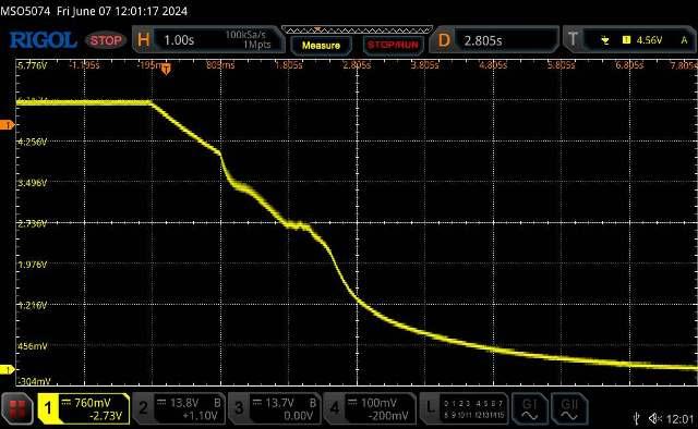 Compare the one above with the old regulator below- which BTW has been running like this, faultlessly for months, and over numerous power cycles every single day in testing. Doesn't warrant the 1000uf cap in my opinion. However I would fit a small 330uf to the LCD 5v PCB and one across the LCD plug in the controller - just to dampen anything from the 5v lead to the LCD. OLD REGULATOR: Edited 2024-06-07 14:55 by KeepIS NANO:Inverter V 8.4ks - Linux AvrDude GUI script V4.1 |
||||
| The Back Shed's forum code is written, and hosted, in Australia. | © JAQ Software 2026 |
