
|
|
Forum Index : Microcontroller and PC projects : Flash 3 common catode LED lamps.
| Author | Message | ||||
| PeterB Guru Joined: 05/02/2015 Location: AustraliaPosts: 669 |
Tinine. With an AC SSR you have to be careful when using inductive loads. It is usually necessary to use a snubber. Other than that they are very useful things. I had a problem with a DC SSR when the internal reverse diode allowed current to flow in the reverse direction. Bob. At 2 am this morning I was trying to work my way around the bootstrap to improve it but I went to sleep. Peter |
||||
| PeterB Guru Joined: 05/02/2015 Location: AustraliaPosts: 669 |
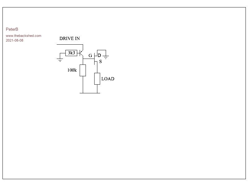 How about this? unfortunately I left -28V off the bottom rail. |
||||
| bob.steel Senior Member Joined: 27/02/2020 Location: AustraliaPosts: 188 |
So I reverse it upside down then for +28v ? What do I need on the input drive a 10K? Do I need a zener anywhere? See from where I've been and whats been discussed I had capacitor ,diode and even a zener at times before . So what can I blow up with this circuit? Only the Arduino board is really important ,the others I have thousands. 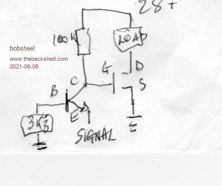 Edited 2021-08-08 17:21 by bob.steel |
||||
| PeterB Guru Joined: 05/02/2015 Location: AustraliaPosts: 669 |
Bob. That would work for an opposite FET and the ARDUINO would be connected to GND and -5V and you want the load connected to GND. My cct will work (I hope) but it does mean having a +5V rail for the ARDUINO and a -28V rail for your LEDs. Having two rails is good for noise. Do you have a problem with using a -28V rail? No 10k needed. Would you like a run-down on how it works? I think it should cost about 25c. Peter (my schematics are nicer than yours)  Edited 2021-08-08 17:29 by PeterB |
||||
| Mixtel90 Guru Joined: 05/10/2019 Location: United KingdomPosts: 8911 |
No good. Remember the LEDs are common cathode. That has to be grounded or at -28v. A high side driver is necessary. Mick Zilog Inside! nascom.info for Nascom & Gemini Preliminary MMBasic docs & my PCB designs |
||||
| PeterB Guru Joined: 05/02/2015 Location: AustraliaPosts: 669 |
Mick. You had me worried there but you are wrong. The entire cct could be moved up 28V so that the ARDUINO is between +28V and +33V. You then have a high side driver. Er, I think. Peter |
||||
| bob.steel Senior Member Joined: 27/02/2020 Location: AustraliaPosts: 188 |
No I dont agree with that either. It can be high or low as long as the current flows pos to negative through the load lights . I have found that in my trials but getting a clean off seems to be causing the problems hence the bootstrap circuit I used but which inverts the signal so its on when it should be off but its a nice clean on and off. In light of the comments on power useage being the same on high and low I am going to try inverting the arduino code and that might be an end of it. If I can follow PeterB's circuit Ill try that too. Its just getting confusing here now and I need to get something operational. Thanks to all though! Edited 2021-08-08 19:03 by bob.steel |
||||
| PeterB Guru Joined: 05/02/2015 Location: AustraliaPosts: 669 |
Bob. My latest (and greatest) can be configured for high or low input it matters not. You do seem a bit worried about blowing up your ARDUINO so 2 questions, which ARDUINO are you using Are you anywhere near OZ. If you are I can send you some mini pro's which would do for testing. I am confident that my cct. will work but I wish other people would confirm it. Peter |
||||
| Mixtel90 Guru Joined: 05/10/2019 Location: United KingdomPosts: 8911 |
Apparently the LEDs are common cathode. It doesn't matter how you label the supply voltages, the cathode of the LEDs has to be the most negative. You are feeding positive into the anodes independently in order to light them. Therefore it *has* to be a high side driver. There's no other possible arrangement. You can feed from 0v to -28v or from +28v to 0v but it's *always* from the high side (most positive) to the low side (most negative). Either way you get the anode of the LED at 28v positive to its cathode to light it. The sketch that you just posted, Bob, should work fine, but will only drive a single LED. It's no use for common cathode LEDs as you can only connect one. I'm not sure what you are showing with the transistor base, but it should be a resistor to +5v. With SIGNAL high the transistor is off and the mosfet is on. Interesting arrangement, PeterB. :) The supply *has* to be -28v relative to GND and the arduino supply +5v to GND. It should work, I think... you are getting the gate 5v above the drain to switch it on. The DRIVE in input is "right way up" too. I like it. :) You can't invert this design with the mosfets you have, Bob. Mick Zilog Inside! nascom.info for Nascom & Gemini Preliminary MMBasic docs & my PCB designs |
||||
| bob.steel Senior Member Joined: 27/02/2020 Location: AustraliaPosts: 188 |
OK Appreciate your input . A lot of negativity I see . So what circuit do you suggest I use ? . Have you actually built any of these circuits in this thread?I have the bootstrap ciruit running without any resistor on the trigger signal . I would have 3 of these circuits on the one board to run 3 LED lighrs . I don't know how to build a minus 28 volts circuit peter . My supply is +28v and I will use a DC to DC converter circuit to get 5 volts at this stage and then try to build in a 7805 or equivalent to my final board. I just don't know how to construct your circuit on a breadboard from what I have available. You know , how do I build a -28 volt supply? Thanks for the offer . I have some nanos myself and some ATTiny's and 328P chips. The board am using atm is a Duemilanove but I have a couple of nanos screwed to the board beside it and a few loose mini pros . $3 a piece jobs. I paid about $35 for the duemilanove back about 2015 or so and I blew up another similar doing this a couple of weeks ago. I'm up at Cairns ,on a boat on the reef mostly with a stud cattle home base and a security business if covid stays away long enough. Ran into an ex hospital nurse recently that tells me covid does not exist and I havent seen any bodies yet so its difficlt to argue with him and fruitless to try. nutters abound . Edited 2021-08-09 08:01 by bob.steel |
||||
| Mixtel90 Guru Joined: 05/10/2019 Location: United KingdomPosts: 8911 |
No, I've not built any of these. :) You have a strange requirement though. Normally people would choose the components to do the job rather than try to lever existing components to fit. I spent many years with that approach though. lol How are you getting the 28v, Bob? In this instance we aren't particularly bothered which supply line is grounded - if any. You can think of it as 0v, +28v and +33v or as -28v, 0v, +5v. It doesn't matter. Only the relationship between the supplies matters. If the 28v is coming from, say, an existing site battery system then it may have one side grounded already, but your application doesn't care about a ground so don't put one on. PeterB's circuit would use an *isolated* 5v dc/dc converter with it's -ve connected to the mosfet drain. The arduino would then be powered on that 5v supply. You can think of the LED cathodes being at -28v if you like, or you can think of the arduino being floated at 28v above 0v. :) Mick Zilog Inside! nascom.info for Nascom & Gemini Preliminary MMBasic docs & my PCB designs |
||||
| bob.steel Senior Member Joined: 27/02/2020 Location: AustraliaPosts: 188 |
Does it matter how the 28v is obtained ? I won't have two separate supplies available only one plus 28 volts I have said before I have hundreds of N channel mosfets and as I have 20 sets of lights to build ,3 mosfets per board that's 60 odd needed.One ATTiny and maybe one 7805 per board. Mostly the 28 volts is from LiFePo4 battery supply ,Solar supplied ,some fed off 54 volt supplies ,some off 2 of 12 volt Li Ion 26v batteries some lead acid . Some from A/C transformed to DC with wall warts. You are starting to wrankle me because its obvious you have not read through the thread and are just popping in and out with negativity and not really adding or trying the stuff suggested . I don't mind much usually but keep in mind casting negativity causes doubt in my mind so its sending me backwards and I need to get a circuit settled. See you have not told me how to build a -28 volt circuit or answered my questions at all! Just criticised . How can that help anyone trying to learn by asking questions? I'd really appreciate it if you would just leave it be . Edited 2021-08-09 08:43 by bob.steel |
||||
| bob.steel Senior Member Joined: 27/02/2020 Location: AustraliaPosts: 188 |
Yes please. Can I do it by splitting the supply to 22 volts and 5 volts? The lights will still run at almost full intensity at 22 volts I have seen. Edited 2021-08-09 08:52 by bob.steel |
||||
| Warpspeed Guru Joined: 09/08/2007 Location: AustraliaPosts: 4406 |
https://pdf1.alldatasheet.com/datasheet-pdf/view/120812/ALLEGRO/UDN2981A.html Cheers, ĀTony. |
||||
| PeterB Guru Joined: 05/02/2015 Location: AustraliaPosts: 669 |
Bob. I think Mick was just trying to understand a bit more detail. I'm doing the washing today so might be a bit slow. If you start by imagining a 5Volt battery connected in series with a 28Volt battery giving 33Volts end to end. we can designate any point as ground so we can have +28V & -5V or -28V & +5V or +28V & +33V, it just depend on what we call ground. And that ground is just a local ground. If the 28V battery is a generator or a mains supply or pins in a lemon it can have its own ground. The main point is that we can have our own local ground which could be a Mega volt above some other point, so long as multiple different grounds are not connected. The idea of calling them ground is misleading but that's how it is. So if you have 2 wires with 28V between them you have a -28V supply. It doesn't matter if that -28V wire is connected to the chassis of a generator and the other wire is red and has a +28V label, as far as our local circuit cares, we have -28V. The problem is however, given the big range of supplies you have to use, how to generate that +5V supply without spending money. It really does look like the VOM1271 is a good idea. To understand my circuit you have to stand on your head. PNP transistors need a -ve rail and so are drawn upside down. With the base connected via a 3k3 to GND. pulling the emitter up to +5V will turn the thing on and its collector will go to +5V. Dropping the emitter to GND turns the thing off and it collector will fall to -28V. In the early days of transistors they were all PNP (OC71) and there were people standing on their heads all over the place. Peter |
||||
| Tinine Guru Joined: 30/03/2016 Location: United KingdomPosts: 1646 |
Oh I have a minimum of 48 SSRs in every control-system that I have built since the mid-80s (thousands). I typically use the Opto-22 modules. I grabbed a bunch of these Fotek relays, mainly out of curiosity.  |
||||
| Tinine Guru Joined: 30/03/2016 Location: United KingdomPosts: 1646 |
Pretty certain that we're on thin ice with this topic but this might be worth sharing....all one needs to do is show the existence of something that hasn't been isolated...oh wait  Alberta fails to provide evidence |
||||
| PeterB Guru Joined: 05/02/2015 Location: AustraliaPosts: 669 |
Not sure if you are agreeing with me or not but. We had some power supplies made for a customer who decided to turn them on remotely using SSRs. Sadly the transformers started to blow smoke. This was 30 years ago and things may have changed but the problem was each SSR had 2 back to back SCRs fired by some sort of pulse. With an inductive load current builds up according to di/dt = E/L and if the build up is too slow the SCR holding current will not be reached and the SCR will not latch. In our case 1 SCR would latch and not the other which resulted in half wave AC = DC going into the transformer and smoke coming out. Fortunately it was not my fault but it is the sort of thing that can keep you awake at night. My only experience with a DC SSR involved a battery on each end and that's when I discovered the reverse diode. Peter Didn't see your second post. P Edited 2021-08-09 17:18 by PeterB |
||||
| Volhout Guru Joined: 05/03/2018 Location: NetherlandsPosts: 5931 |
This is by far the longest thread I have seen on lighting a LED. I have absolutely no idea what is holding Bob on building the proven PLC circuit I showed here. PLC output circuit Unless this is technically beyond his capabilities (no offense meant ! not everybody is an electrical engineer, and can read schematics and know what they mean), then all discussions in this thread are beyond his capabilities. And we should suggest hey purchases a build up output card. Simplest is one with mechanical relays. And cheap. Regards, Volhout PicomiteVGA PETSCII ROBOTS |
||||
| Warpspeed Guru Joined: 09/08/2007 Location: AustraliaPosts: 4406 |
Oh this is the second very long thread on lighting a couple of LEDs, and Bob is not any closer now than he was after the very first reply in the other thread. Cheers, ĀTony. |
||||
| The Back Shed's forum code is written, and hosted, in Australia. | © JAQ Software 2026 |
