
|
|
Forum Index : Electronics : Various aspects of home brew inverters
| Author | Message | ||||
| Solar Mike Guru Joined: 08/02/2015 Location: New ZealandPosts: 1228 |
I traced out part of the IR2110 boost circuit for the 7500 watt inverter, the boost drivers are Tip41\42C emitter follower pair, each pair driving 5 x HY4008 parallel mosfets in one leg of the H-Bridge. No gate to source resistors are used here, just the single 5K resistor as shown. The bootstrap diode UF4007 charges the upper bias caps to 12 volts when the lower mosfet turns on. 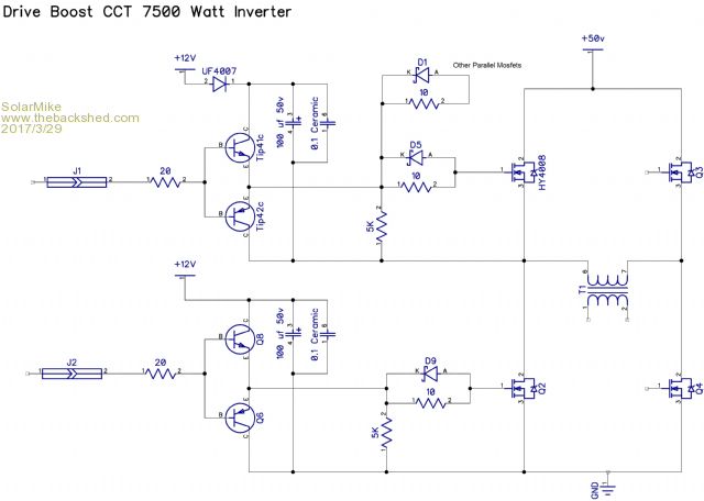 Cheers Mike |
||||
| Tinker Guru Joined: 07/11/2007 Location: AustraliaPosts: 1904 |
Interesting, what kind of value zener diode would be there in parallel with the 10 Ohm resistor? Thanks for tracing it out. No doubt mad will try this in no time  . I'll wait for a while for results, too busy with other things here. . I'll wait for a while for results, too busy with other things here.Klaus |
||||
| Solar Mike Guru Joined: 08/02/2015 Location: New ZealandPosts: 1228 |
Umm its meant to be a small signal schottky diode, according to Diptrace Schematic symbols. Mike |
||||
oztules Guru Joined: 26/07/2007 Location: AustraliaPosts: 1686 |
Thanks Mike... so far I don't seem to need it, but it would be sensible to action it anyway I think. Have you driven that board to see how it stands up? ......oztules Village idiot...or... just another hack out of his depth |
||||
Madness Guru Joined: 08/10/2011 Location: AustraliaPosts: 2498 |
Thank you Mike, greatly appreciated, I will get onto it very soon, have a few busy days ahead. But if we get flooded in by the tail end of excyclone Debbie I will be onto this. Interesting with the single 5K GS resistor and that is on the driver side of the gate diode/resistor. I received 100 HY4008's yesterday, 5 in each bank should be as good as or better than 6 4110's. Just need some TIP41c's and 42c's, Jaycar have them in stock. There are only 10 types of people in the world: those who understand binary, and those who don't. |
||||
| Solar Mike Guru Joined: 08/02/2015 Location: New ZealandPosts: 1228 |
As yet no, it uses a version of the UPS SPWM generic drive PCB sub board with its EG8010 chip, probably should isolate the over current shutdown circuit on it before firing it up on a torroidal transformer. I was going to use it in another, smaller inverter application; too busy renovating a house at the moment also. |
||||
| Solar Mike Guru Joined: 08/02/2015 Location: New ZealandPosts: 1228 |
I guess it saves having to solder in 20 resistors, there is no reason why their method isnt valid, its hardly likely to go open circuit and allow the gates to float. I dont know how fast those TIP41\42 buffers can switch, need someone to build it and look at the waveform with a storage scope. HY4008's are beefy, 80v rating though, there must be a way to run the inverter on a lower voltage temporarily so any voltage ringing spikes across the mosfets can be looked at with a scope, to ascertain whether the RC snubbers are correct. In fact as any ringing is dependant on the torroidal core, lead lengths etc, I would remove the snubbers, run it at a lower voltage and measure the frequency of any ringing, then calculate snubber values accordingly, this would give optimal results at 50v supply. Cheers Mike |
||||
| Madness Guru Joined: 08/10/2011 Location: AustraliaPosts: 2498 |
Hi Mike, Do you know what components they have used for the Snubbers? Also on that link I posted they appear to have a cap identical or very similar to the 0.1uf piggybacked on a resistor near each pair of TIPs. Hopefully their design is robust with a range of transformers, being sold for DIY building Inverters there would be many different arrangements. I have the PCB design ready but will be a couple days before I have time to make the actual PCB. PS Just had another look at the pictures online and I can not see any sign of Snubbers could they be between the heatsinks? There are only 10 types of people in the world: those who understand binary, and those who don't. |
||||
| Solar Mike Guru Joined: 08/02/2015 Location: New ZealandPosts: 1228 |
Glad you asked to look at it again, I put my glasses on this time, that cap is wired in parallel to the 5k resistor; also there are no snubbers on the board. I have added to my schematic below. Doesnt seem logical to place a cap of that size there, unless they intend to delay the switching of the lower bridge relative to the upper, but it will be loading down the booster circuit with extra capacitance. 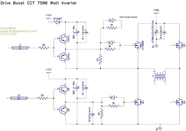 |
||||
| Madness Guru Joined: 08/10/2011 Location: AustraliaPosts: 2498 |
Thanks for the quick response Mike, I will make it the same with just 4 MOSFETs to start with, test and add more once I know it will run okay. There are only 10 types of people in the world: those who understand binary, and those who don't. |
||||
| Madness Guru Joined: 08/10/2011 Location: AustraliaPosts: 2498 |
Here is my PCB, it includes 12 volt power supply and MOV's for lightning protection. 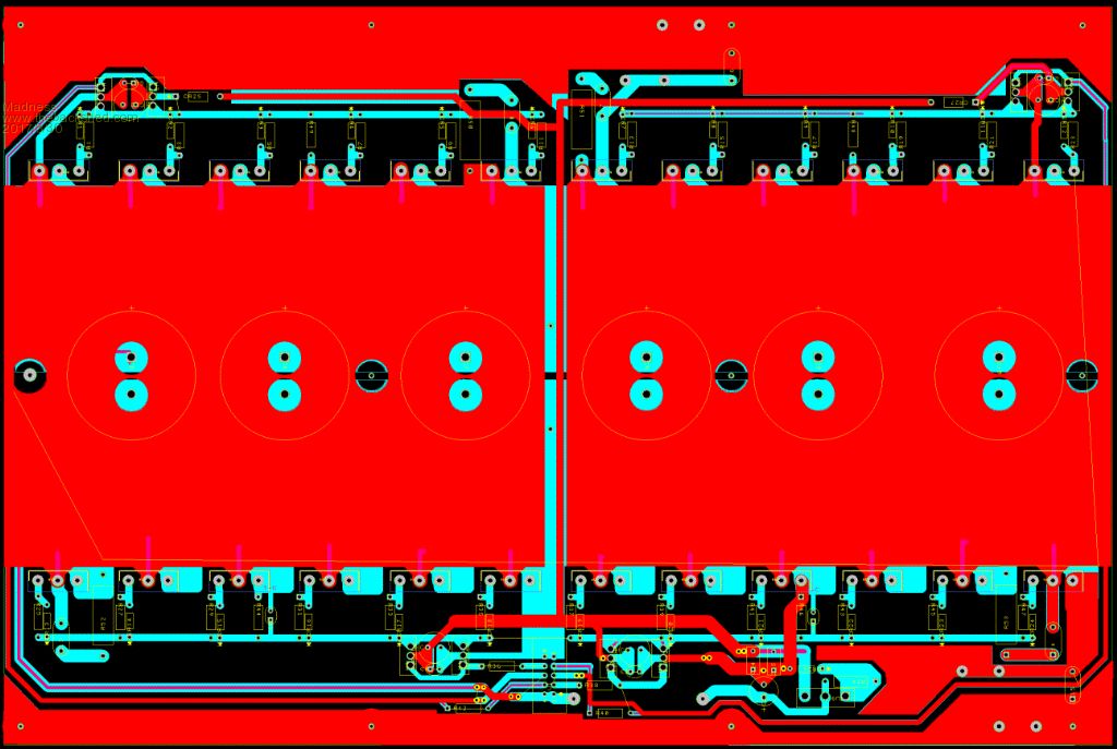 Also PDF's, these are mirrored ready for toner transfer but they require A3 paper and 200 X 300 MM PCB. 2017-03-30_210435_7.5_top.pdf 2017-03-30_210502_7.5_bottom.pdf There are only 10 types of people in the world: those who understand binary, and those who don't. |
||||
| poida Guru Joined: 02/02/2017 Location: AustraliaPosts: 1480 |
Part 5: Experiments with the control loop First a little review of some things that are important to understand. (forgive me if you already know what follows, and correct me when I am wrong, please) The inverter we are all building and hacking uses a closed loop control design which takes a DC sample of the output AC voltage on the transformer secondary. This DC voltage (Vfb) may have a lot of 100Hz ripple (if a full bridge rectifier is used, else 50Hz ripple), and unknown amounts of much higher frequency noise mostly coming from the full bridge mosfet switching of the DC supply. We need to filter Vfb to only let DC into the control loop. In another post somewhere I showed that the EG8010 IC only samples Vfb during a very short time compared to the 20 ms period of 50Hz output. I think I wrote that Vfb is sampled at the top of one half of the 50Hz output waveform, and the sample window is of the order of 10us. For the rest of the (20milliseconds - 10us) period, Vfb is not sampled. This means that we need to have Vfb reflect accurately what the output voltage is during that sample time. Vfb may go all over the place during times when the EG8010 is not sampling it�s value. The fact that Vfb is sampled synchronously with the output waveform might lead us to simple Vfb filtering designs which work fine on the test bench, usually with purely resistive loads. In the real world the current and voltage can be way out of whack. This will upset the closed loop control leading to over/under voltage of the output. So we have to low pass filter Vfb quite heavily to allow for large disturbances from various load types (switching power supplies, SCR controlled lights, motors, flouro lights etc) I have built a custom inverter prototype using the Arduino (ATMega 328) so as to permit complete control over all aspects of the inverter function. I can use any sort of digital low pass filtering of Vfb I choose. I could do the filtering in hardware but I prefer the flexibility of software. At last it�s time to look at some results of the closed loop output voltage control. I use a simple design: Vfb is fed into one of the ADC ports and is filtered to remove all the high frequency stuff. The 100Hz ripple is quite high, about 0.3V p/p riding on a 2.5V DC signal. I then sample this voltage about 2,200 or 8,000 times a second and apply some digital filtering to it. Then at the zero Voltage point in the beginning of each 50Hz output, I apply this filtered Vfb value to the PID control loop to calculate the needed PWM duty cycle %. Digital filtering is done in two ways. Method 1 is a simple single pole recursive low pass filter - 8,000 Hz sample rate a = the time constant, in my case a = 0.01. Initialise ma_ch0 = 0.0 the ADC input is named new_ch0 the filtered output is named ma_ch0 ma_ch0 = ma_ch0 * (1.0 - a) + new_ch0 * a Method 2is a 4 pole Bessel low pass filter - 2,200 Hz sample rate It needs a lot more calculations per sample but even on the Arduino it runs at 2,200 Hz let ch0 = the ADC input value At the end of these calcs the filtered output is also named ch0 xv[0] = xv[1]; xv[1] = xv[2]; xv[2] = xv[3]; xv[3] = xv[4]; xv[4] = ch0 / 2.259747797e+05; yv[0] = yv[1]; yv[1] = yv[2]; yv[2] = yv[3]; yv[3] = yv[4]; yv[4] = (xv[0] + xv[4]) + 4 * (xv[1] + xv[3]) + 6 * xv[2] + ( -0.7428578687 * yv[0]) + ( 3.1954036268 * yv[1]) + ( -5.1599230905 * yv[2]) + ( 3.7073065280 * yv[3]); ch0 = yv[4]; Those ugly coefficients are not easy to calculate and these come from a hugely helpful website at https://www-users.cs.york.ac.uk/~fisher/mkfilter/trad.html I used an Fc of 0.01 (e.g. 1000 sample rate and 10 Hz Fc) 4 poles, Bessel LP filter to get these numbers. With a cutoff frequency (Fc) of 0.01, and the 2,200 Hz sample rate, the -3db point is about 22 Hz. These two methods of LP filtering Vfb behave rather well with the PID control. Method 1 removes all the 100Hz ripple, as does method 2. The difference is in the details. All digital filtering creates a delay in the filtered output compared with the unfiltered source signal. This delay can really screw up the PID control loop if you let it get too long. Imagine if Vfb lagged so much when the control loop increases it�s output so that it starts oscillating..Bad things will happen. Method 1 gives a smooth result with acceptable delay. Method 2 gives a smooth result with less of the delay of method 1 which permits a faster responding PID control loop. I tried Butterworth LP filters but these have a unwanted overshoot on a step input. This means the filtered signal will follow Vfb as it rises and continue to rise a bit more when Vfb stabilises. Then return back to the correct value. Overshoot is bad when present in the input of a PID loop. So I was forced to use the Bessel filter which has no overshoot with small Fc values. Time for some pictures. yellow is DC bus current, dark blue is AC output voltage pink is PWM duty cycle % light blue is digital filtered Vfb as used by the PID control loop using method 1 It took about 10 cycles to settle Notice Vfb minimum is about 4 cycles delayed from AC output. 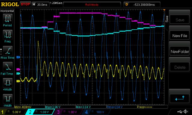 using method 2 It took about 8 cycles to settle. Vfb minimum is not as delayed, it�s about 3 cycles now. Looking at the pink trace - PWM duty cycle - you can see that the control loop can assert control much easier with the shorter delay. It needs less time at max PWM to get the output voltage back up. Also I think I am letting some faster changes in Vfb through the filter and into the PID control. (think less attenuation of 10Hz signals compared with method 1) 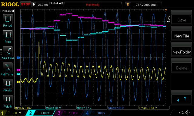 There is not a huge amount to gain in all this. I find this sort of investigation a great way to spend some time and it helps me understand what is going on. (pink and light blue traces are swapped now.) This is when it oscillated, due too too much PID gain and too much delay. I did not damage my inverter when this happened. I use current limited power supplies which lets me get away with murder. 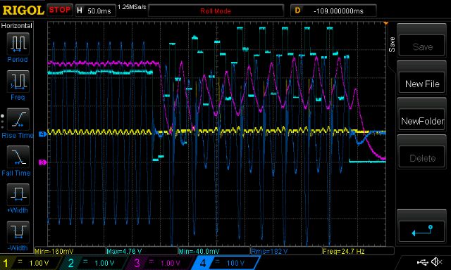 Finally I removed the low pass filtering to see if the control loop will get upset. It was completely untroubled as you can see. This is due to Vfb sample time being at the start of the 50Hz cycle every time. 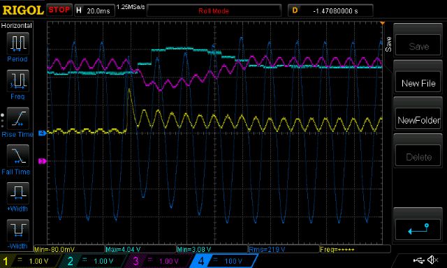 wronger than a phone book full of wrong phone numbers |
||||
| Warpspeed Guru Joined: 09/08/2007 Location: AustraliaPosts: 4406 |
That is a heroic effort ! I have had a few goes at something similar a very long time ago, but all my efforts were in pure hardware. From memory my best result was with a full wave precision rectifier followed by an active filter with a cutoff frequency set at a very few Hz. Cheers, �Tony. |
||||
| Madness Guru Joined: 08/10/2011 Location: AustraliaPosts: 2498 |
Great effort there Poida, can admin remove the newbie title from your account  There are only 10 types of people in the world: those who understand binary, and those who don't. |
||||
| poida Guru Joined: 02/02/2017 Location: AustraliaPosts: 1480 |
Thanks guys, I'm glad you found it interesting. wronger than a phone book full of wrong phone numbers |
||||
| oztules Guru Joined: 26/07/2007 Location: AustraliaPosts: 1686 |
Simply amazing research Poida..... ........oztules Village idiot...or... just another hack out of his depth |
||||
| Mulver Senior Member Joined: 27/02/2017 Location: AustraliaPosts: 160 |
Yes awesome work ! Very interesting!! |
||||
| poida Guru Joined: 02/02/2017 Location: AustraliaPosts: 1480 |
Part 6 - transformer resonance and a look at primary winding current After reading Warpspeed�s post on transformer resonance I thought I wanted to see it. So, the experiment is set up using - a sig gen with it�s output configured to drive 50 ohm output - a 47R resistor, insures with the transformer winding under test. - one DSO channel looking at sig gen voltage output - other channel looking at transformer winding voltage - sweep sine wave from low to high, with a sort of constant amplitude. Transformer self resonance can be viewed as a LC tank. Resonant frequency (Hz) = 1/( 2 x pi x sqrt(L.C) ) I use the 1000VA Aerosharp toroid, 25 turns primary. I use the factory wound 240V secondary winding. I�m lucky to have a BK Precision 879B LCR meter which lets me measure at 100, 1K and 10KHz. At 100Hz, the primary is 10.6mH with Secondary open, when secondary shorted, the primary becomes 10uH. This 10uH is the leakage inductance. This is not very much at all. first is 20 - 20KHz sweep, 1v p/p ,2KHz/div horizontal scale yellow is sig gen output, light blue is primary winding voltage 0.97uF cap across secondary 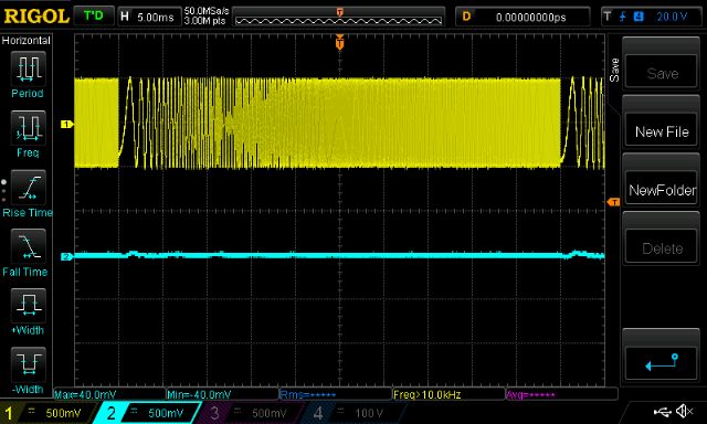 Next shows when secondary is open Note resonance, peak around 4Khz 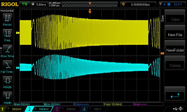 This has the secondary connected to a small 75 VA 240V->25V toroid, into the 240V winding. Still has the resonance, same peak location. It�s clear the capacitor does a huge job. Both alter resonance and moderate PWM switch noise. 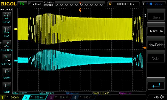 Now it gets interesting. This shows the resonance of my standard test circuit. The primary has the 50uH choke, the secondary is connected to the 9V Vfb transformer and has a 5uF cap across it. frequency sweep is now 20Hz - 100KHz Look at that! Up around 80KHz this circuit wants to boogie! 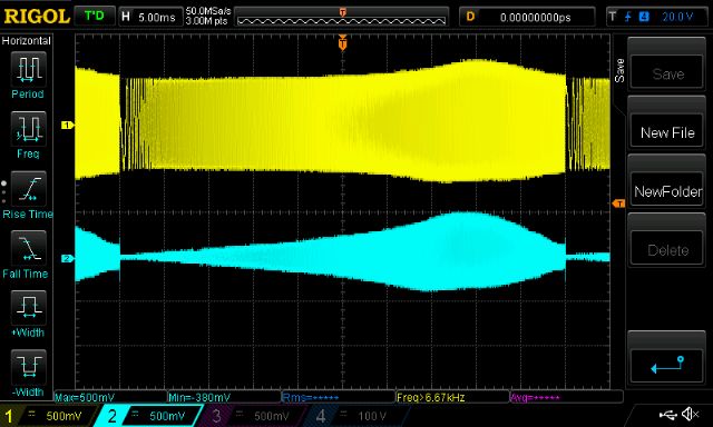 And most surprisingly, when I just omit the 50uH choke, the resonance becomes normal. 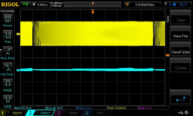 So after seeing all this I still see the clear need for a choke (or inductor) in the primary. This is needed to moderate the PWM current peaks. Time to see the primary winding current I inserted a short 3mm copper solid wire with a LEM CASR15 current sensor into the primary circuit. This now gives me a view of the current flowing through the mosfet bridge outputs (and primary winding and the choke too. It�s all in series) Yellow is DC bus current (about 5A/division) Blue is AC output Pink is primary current. Scale is 41.7mV/Amp or about 5A/200mV division First is idle load. I can see the current leading the AC output, as it should. Look at the strange disturbances in the current when AC output zero crosses. Warpspeed may find this of particular interest. Something is happening here. But what it is, I have no idea. 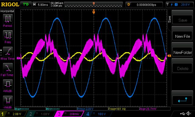 Next is a close-up, which shows the charge up/down of the primary circuit inductance for each of the 20KHz PWM cycles. 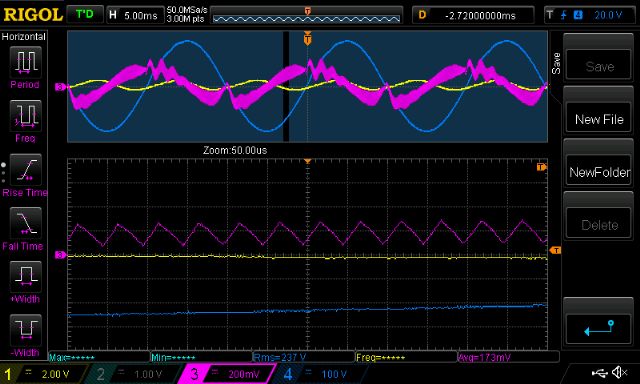 Finally this shows it under my test load, about 170W AC RMS (DC supply 30V) The primary current is now a lot better looking but still has the zero cross disturbances. 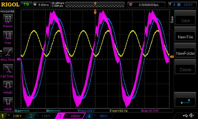 Anyway I hope this helps us get a better grip on what�s happening with our systems. As usual, please correct me when I am wrong. wronger than a phone book full of wrong phone numbers |
||||
| poida Guru Joined: 02/02/2017 Location: AustraliaPosts: 1480 |
sorry. seems I posted this twice. wronger than a phone book full of wrong phone numbers |
||||
| Madness Guru Joined: 08/10/2011 Location: AustraliaPosts: 2498 |
I have had issues with posting today also. There are only 10 types of people in the world: those who understand binary, and those who don't. |
||||
| The Back Shed's forum code is written, and hosted, in Australia. | © JAQ Software 2026 |
