
|
|
Forum Index : Electronics : Various aspects of home brew inverters
| Author | Message | ||||
| Warpspeed Guru Joined: 09/08/2007 Location: AustraliaPosts: 4406 |
Well worth a go. Another quick thought. As this will be sometimes working right down to zero dc volts, and at very low switching frequencies, the mosfet gate drivers will be much better if they are continuously and independently dc powered. The usual charge pump for the upper gate driver will definitely give you some grief. I used a pair of small mains transformer/rectifiers to supply isolated gate drive power. Very interesting gapping the E core. Ferrite is still going to saturate at about 0.35 Teslas even with a gap. Good grain oriented steel saturates at probably closer to 1.3 Teslas. All else being equal, thats about three times the ampere turns. Cheers, �Tony. |
||||
| Tinker Guru Joined: 07/11/2007 Location: AustraliaPosts: 1904 |
Tony, would this: schottky diode be OK for your circuit above? I also have some Allegro (ACS758)Hall effect 100A current sensors plus ginormous capacitors, so building your device is almost done  Klaus |
||||
| Warpspeed Guru Joined: 09/08/2007 Location: AustraliaPosts: 4406 |
Oh yes lovely. Its not really the fast recovery speed we require, but the low forward voltage drop. That makes the whole thing more efficient, as well as requiring less heat sinking. I think you will be amazed at how easy it is to reach very high peak currents with so little dc input power. Cheers, �Tony. |
||||
| Solar Mike Guru Joined: 08/02/2015 Location: New ZealandPosts: 1212 |
Tony would those ACS758 Hall Effect sensors have enough bandwidth to pick up the current change, or would it be better to use a sense resistor and a differential probe on the scope as this would be faster. spec ACS758 � 120 kHz typical bandwidth � 3 μs output rise time in response to step input current Cheers Mike |
||||
| Warpspeed Guru Joined: 09/08/2007 Location: AustraliaPosts: 4406 |
Heaps of bandwidth for this. We will usually be switching at quite a low frequency, and the gentle ramping up and down is a very slow change with no fast edges anywhere. But as there are some very high circulating currents, and the mosfets and diodes do switch fast, there can potentially be a lot of switching noise and nowhere a clean ground reference. A sense resistor is going to only produce a low voltage unless its very lossy, and differential measurement of a low amplitude noisy signal is difficult, unless you have really good equipment. All sorts of problems with current transformers, although in theory it should be possible. Hall device gives complete isolation, frequency response down to zero, and usually several volts of nice clean output. A further advantage is you can very easily increase the sensitivity by looping several turns through a high current Hall sensor. I have a 75 amp Hall sensor (LA55P) glued onto the end of a plastic box which contains a +/-15v dc power supply inside. I just grab that and plug it into the mains, and plug the coax output into my oscilloscope. Its my "big" current probe ready for instant use at any time. Often quite useful for many other things besides choke testing. My tester is in another plastic box. It has an opto isolator input driving a divide by two flip flop. That feeds into an IR2110 gate driver. There are a pair of small mains power supplies to provide two separate 12v supplies. The mosfets and diodes are sized for an easy peak 80 amps. No point in going higher as that is about where my Hall sensor tops out. I initially blew up quite a few mosfets until I became much more careful in using this tester. But with a bit of care and some familiarity it has served me very well. Sorry still no camera here. Cheers, �Tony. |
||||
| Warpspeed Guru Joined: 09/08/2007 Location: AustraliaPosts: 4406 |
Oh, I meant to say that current transformers can never produce a perfect square wave output with a square wave input current. The top of the waveform always has some tilt or downward slope that may be very slight or extreme. It depends on the inductance of the CT and the value of the burden resistor. As we may be switching our choke at a very low repetition rate, the very last thing we want is to add some unknown extra slope into the current ramp we are looking at. The introduced errors will likely make a complete nonsense of the whole exercise. So forget about current transformers. We need dc coupling and a frequency response for the current measurement right down to zero frequency for this. Cheers, �Tony. |
||||
| Solar Mike Guru Joined: 08/02/2015 Location: New ZealandPosts: 1212 |
Thanks for that, what an excellent idea, another project .... where will it end  Have ordered a couple of those LA55-P's from AliExpress (LA55-P) seem cheap enough, hope they are not fakes. Which reminds me, recently I ordered some IRFP4468's from RS here in NZ and out of 30, 3 were suspect fakes and had to be sent back to RS, they didnt meet spec and had incorrect case markings, They very smartly shipped out replacements, so nothing can be trusted, would be very interesting how they got into their supply chain. Mike |
||||
| Warpspeed Guru Joined: 09/08/2007 Location: AustraliaPosts: 4406 |
I was sent by the Devil to keep you guys busy. Cheers, �Tony. |
||||
Revlac Guru Joined: 31/12/2016 Location: AustraliaPosts: 1276 |
This is all looking interesting, I found this document (AN4070) 250 W grid connected microinverter. just thought someone might find something useful in it. Cheers Aaron Cheers Aaron Off The Grid |
||||
| Warpspeed Guru Joined: 09/08/2007 Location: AustraliaPosts: 4406 |
Here: http://www.st.com/content/ccc/resource/technical/document/application_note/fa/f1/fe/3d/81/1e/47/45/DM00050692.pdf/files/ DM00050692.pdf/jcr:content/translations/en.DM00050692.pdf Cheers, �Tony. |
||||
| poida Guru Joined: 02/02/2017 Location: AustraliaPosts: 1476 |
Part 9: Air core inductor possible or am I on drugs.. Air cored inductors can not saturate and so I wondered is it feasible to make one for our home brew inverters. From the wikipedia inductor page for a short air core coil we have L = (r2 x N2)/(9r + 10l) uH where N = turns r = radius of coil (inches) l = height or length of coil (inches) So I had some 1mm diameter single core wire laying about. I made a coil of about 4" diameter, 13 turns, and about 0.3" high The LCR meter measures it at 27.4uH The formula gives (2 x 2 x 13 x 13)/(9 x 2 + 10 x 0.3) = 32 uH Close enough for me. The resistance of this coil is 0.35 Ohms and that may be a problem when it�s passing primary winding currents for realistic loads. It looks like this: 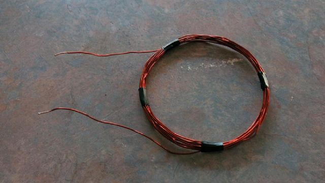 But it works fine, here are the two DSO captures at idle and under 440 W load. idle 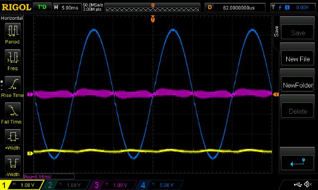 440W load 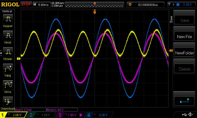 The coil gets hot very quickly and it no wonder why. (pink trace is primary current, 41mV/Amp scale, so 1.44V = 35A) 35 Amps RMS through 0.35 Ohms = 429 W I want to make the same coil with much ticker wire, 13 T of 4� diameter coils means about 4 meters of cable. This wont cost too much. I am thinking that maybe I don�t need anything other than an air core coil as the primary side choke. No more saturation worries! wronger than a phone book full of wrong phone numbers |
||||
| Warpspeed Guru Joined: 09/08/2007 Location: AustraliaPosts: 4406 |
Air cored coils can be very useful, but there is one huge problem. You need a lot of copper wire length and a very great number of turns to reach any reasonable amount of inductance. That increases the resistive copper losses beyond anything acceptable for most power magnetics. As soon as you start using thicker wire, that spaces the individual turns further apart which lowers the inductance. The most efficient proportions for designing an air cored coil are the "Brookes Coil", and there are some software calculators on the internet for designing Brookes coils, or any air cored coil. http://www.nessengr.com/techdata/brooks/brooks.html A magnetic core offers a much more efficient and cost effective solution. Chokes are about the most difficult of magnetic components to design properly, and there is a lot more to it than what follows. But the simplest practical nuts and bolts approach for something fairly ordinary would go something like this: First determine your required wire size from the resistive heating point of view. Fit as many turns as possible onto the prospective magnetic core. Adjust the air gap sufficiently wide so it has an adequate saturation margin. If it then has enough inductance remaining after gapping, the job is done. Or go to a larger core and try again if you still require more inductance. Cheers, �Tony. |
||||
| poida Guru Joined: 02/02/2017 Location: AustraliaPosts: 1476 |
Warp, I only want about 30uH using 35mm2 cable, nominally 11mm diameter. The formula suggests 19 turns, 9.5 inch high, 6.5 inch diameter coil. I would need 9.7m of cable. 0.5 Ohms/km means DC resistance = 4.8 mOhms for the inductor. This seems quite feasible to me. wronger than a phone book full of wrong phone numbers |
||||
| Warpspeed Guru Joined: 09/08/2007 Location: AustraliaPosts: 4406 |
Fine, if you are happy with that. One thing to be aware of is the extensive external magnetic field produced by a large coil like that. Its probably not a problem unless you put it anywhere near large sheets of metal, or even worse fully enclose it in a fairly small metal box. A sheet of metal placed very close acts like a shorted turn which can significantly reduce the inductance. Last time I used something like that it was mounted on a block of wood, and it did work quite well for what I was trying to make it do at the time. Cheers, �Tony. |
||||
| Solar Mike Guru Joined: 08/02/2015 Location: New ZealandPosts: 1212 |
I can endorse what Warpspeed is saying here, my background involved working on 100KW radio transmitters, these used large coils, usually made from copper tubing for the various inductors, in all cases the coil was positioned near the middle of any contained metal cabinet, usually over a cubic meter in volume, any smaller would have drastic effects,a lot of the coils were inside room sized open air enclosures with no metal close by. I dont think an air coil is going to be practical for use in an inverter, one would require a huge box or it would have to be mounted external to it. Cheers Mike |
||||
| Tinker Guru Joined: 07/11/2007 Location: AustraliaPosts: 1904 |
Interesting comments, have not inductive stove tops air cores in them? So Mike, will a iron core (like the choke I was discussing in another thread) be affected if it ends up mounted against a sheet metal cabinet wall? Or is it wiser to space it off a little with a piece of plywood? Klaus |
||||
| poida Guru Joined: 02/02/2017 Location: AustraliaPosts: 1476 |
Oh well, the air core inductors did appear as too good to be true. I ran the above coil at 440 W output for about a minute and shortly after that I saw the electricians tape melting, smoke, etc. As to be expected. Onward and upward. The best approach seems an E core ferrite with a decent sized gap. Or a couple of Aerosharp chokes as Tinker is doing. wronger than a phone book full of wrong phone numbers |
||||
| Solar Mike Guru Joined: 08/02/2015 Location: New ZealandPosts: 1212 |
Induction stoves have an air cored coil, and when you place a magnetic conductive pot on top of it, the pot acts as a shorted turn and by induction sucks whatever energy is being fed into the coil circuit, thus heating the pot. There wont be any problem mounting your choke against the cabnet wall, but keep the surface with the air gap upper most away from the wall, depending on how its bolt holes are positioned, but we dont want the mounting bolts to short the air gap through your metal cabinet, maybe easier to mount on a piece of timber, assuming it wont heat up so much to cause a fire. Cheers Mike |
||||
| Warpspeed Guru Joined: 09/08/2007 Location: AustraliaPosts: 4406 |
All very true. The air cored coil I mentioned earlier was actually half the primary removed from a 150 amp "buzz box" stick welder. It had about 120 turns of about 3mm diameter solid copper wire. It started to complain if a sheet of aluminium came any closer to it than about 35mm. I expect Klaus's choke to have about 100uH and several hundred amps saturation, and the resistance would be very low. Again a wild guess, but say mean length of turn 250mm, ten turns with tails, maybe 3m total wire length. If its 25mm^ 2 wire ? Only 2.06 milliohms. Cheers, �Tony. |
||||
| poida Guru Joined: 02/02/2017 Location: AustraliaPosts: 1476 |
In the quest to find a cheap or zero cost choke I tried one of these from a 400W bay light. I rewound it with 8 1/2 turns, giving 50uH.  here is the inductance test. Conditions have changed. 17V supply, 10.2mV /5.5A = about 2mv/Amp yellow is gate drive, purple is supply, light blue is current 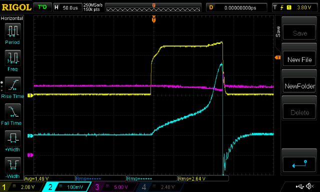 It seems to be good for about 75A The inverter power I am interested in is 700-1200W power levels with peak efficiency and capability to go to 3000W for short times. See following post for my rationale. wronger than a phone book full of wrong phone numbers |
||||
| The Back Shed's forum code is written, and hosted, in Australia. | © JAQ Software 2026 |
