
|
|
Forum Index : Microcontroller and PC projects : MMX-ZERO HAT Stand PCB
| Author | Message | ||||
| matherp Guru Joined: 11/12/2012 Location: United KingdomPosts: 11513 |
Here is a new design for a PCB for the 64-pin MMX. This uses the footprint of the Pi-Zero allowing it to fit in the cheap available Pi cases and interface with the any of the Pi HATs. 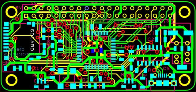 2018-01-02_055448_MMX-zero.pdf The PCB has the usual PIC16LF1454 and mode switch to act as the console and to program the MMX. It has an SDcard located in the same place as the Pi Zero, a reset switch and a heartbeat LED - nothing else other than the required caps and oscillator. The PCB is just 65mm x 30mm and I managed to squeeze everything on using a normal double sided PCB whilst meeting the spacing requirements for the cheapest production costs and using nothing smaller than 1206 parts. The ground plane and 3.3V Heat-sink area for the regulator are omitted in the picture for clarity. As always any comments appreciated before I go to copper. I'll post gerbers once a prototype is tested and working. The intent of the PCB is to build a FLAC music player using an e-INK display and DAC |
||||
Grogster Admin Group Joined: 31/12/2012 Location: New ZealandPosts: 9975 |
Nicely done.  A very tight PCB. Efficient. A very tight PCB. Efficient.  eInk display seems expensive for it's size, but then, I have never used them so..... They are very low power consumption compared to a more standard LCD though, so I guess if you want that saving, you have to pay for it. eInk display seems expensive for it's size, but then, I have never used them so..... They are very low power consumption compared to a more standard LCD though, so I guess if you want that saving, you have to pay for it.  Smoke makes things work. When the smoke gets out, it stops! |
||||
| matherp Guru Joined: 11/12/2012 Location: United KingdomPosts: 11513 |
Boards arrived and one made up. All works perfectly  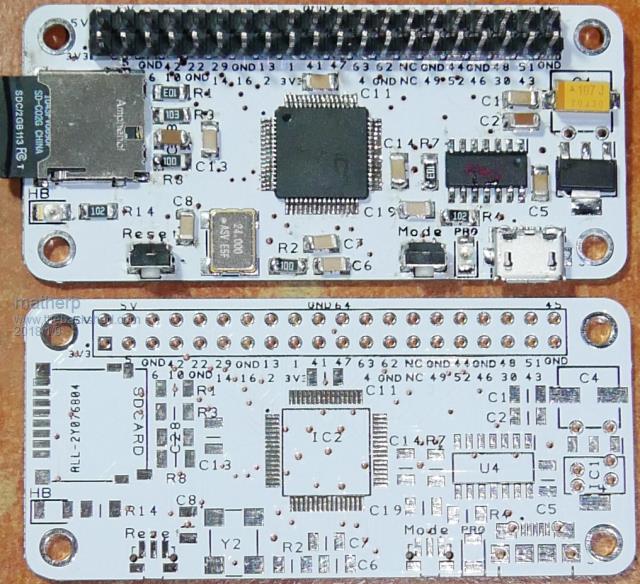 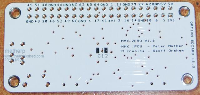 Configuration for ILI9481 480x320 display 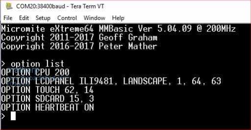 Gerbers 2018-01-09_022202_HAT64.zip I used ALLPCB as an experiment to make the PCBs:- The good: Fast production and shipping with TNT Cheap (NB 1.2mm PCBs cheaper than 1.6mm - shipping weight?) Etch, drilling and plating all seems good Silkscreening very good The bad: Tracks lift easily with heat. Solder resist seems softer than usual NO SOLDER RESIST BETWEEN TQFP PINS _ THIS MAKES SOLDERING THE PIC VERY DIFFICULT |
||||
| Zonker Guru Joined: 18/08/2012 Location: United StatesPosts: 772 |
Wow... Nice layout Peter..!! |
||||
| CaptainBoing Guru Joined: 07/09/2016 Location: United KingdomPosts: 2171 |
yep - looks really nice |
||||
| Bill7300 Senior Member Joined: 05/08/2014 Location: AustraliaPosts: 159 |
Bit of a worry about the lack of resist between TQFP pins though. I'll repeat the experiment using JLCPCB to see if that supplier is any better. Bill Bill |
||||
| Bill7300 Senior Member Joined: 05/08/2014 Location: AustraliaPosts: 159 |
OK, after protracted discussions with jlcpcb.com about the existence of a drill layer and their eventual acceptance that Peter's gerbers were ok, then a 3 day tag session with the courier for DHL here in the wilds of rural Tasmania, but on the main north-south highway and just 30 kms south of the second largest city, I have my 10 boards. As far as I can tell, there does seem to be resist between the pads of the TQFP pins bit I'm recovering from retinal surgery so can't be too emphatic. Now awaiting some chips so I can try and see how easy they are to solder, or otherwise. As this was my first order with them, I got the 10 for the $2 total price, with free shipping! My second order for 3 other pcb designs, cost me $17.98 USD shipping. Even there, it is hardly worth the effort of breaking out the Kinsten etc to produce a prototype. Now, if I can only get my DEX to play nicely on this 32 bit W7 machine, I will know that I'm in Nirvana, rather than just suspecting it! Bill Bill |
||||
| The Back Shed's forum code is written, and hosted, in Australia. | © JAQ Software 2026 |
