
|
|
Forum Index : Electronics : Various aspects of home brew inverters
| Author | Message | ||||
| poida Guru Joined: 02/02/2017 Location: AustraliaPosts: 1476 |
Part 21: Change over from street to inverter and vice versa My solar power system is supplying about 50% of the house's energy needs. I arranged the inverter to switch on when the battery volts are high enough and to switch off when the battery volts reach 48.5V This is for a SLA based 400AH 48V battery, which maintains approx 60-70% capacity when the inverter switches off. This switching on and off of the inverter, averaging about 1 off and 1 on event per day is managed by a Latronics change over switch. Today I show voltage and current waveforms of the change over street to inverter and inverter to street. Some change over events occur when street AC phase is close to inverter AC phase. Other events occurred when they were 180 deg different. I was interested in phase matching the inverter to street AC prior to change over but my experience has shown this is not vital for inverter (&/or household equipment) health. Yellow is inverter current Light Blue is inverter voltage Pink is street voltage Dark Blue is street current Both current and voltage scales are similar, i.e. comparable. This is inverter -> street under light load (200W ish) Phases are close 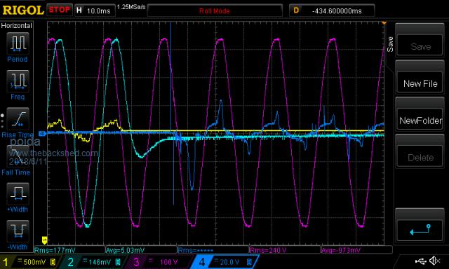 Street -> inverter, same light load. Close phases again 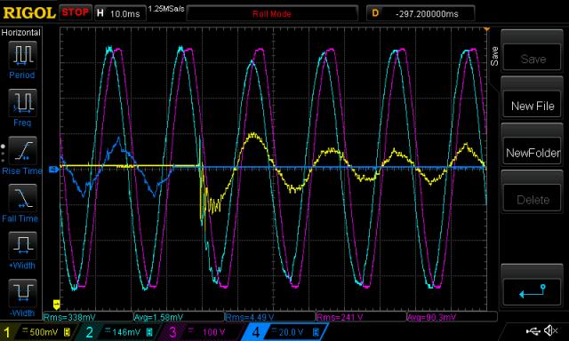 Here is a changeover, street -> inverter 180 deg phase diff. 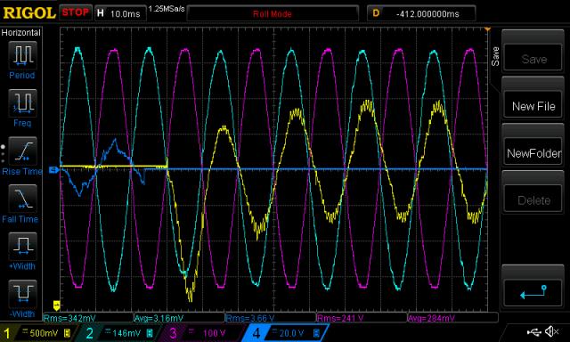 Whoa, dude. This event was accompanied by a loud hum generated by the inverter. This hum dies out after a minute or so. here is inverter - street, same loads as above. Even the street current is large for a few cycles, then it reduces to normal. Same vertical scales, note. 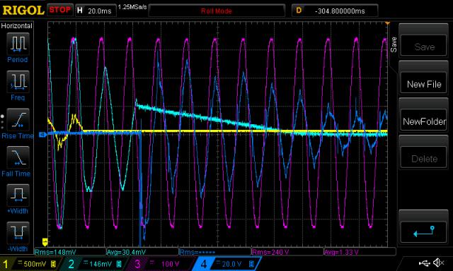 Others: 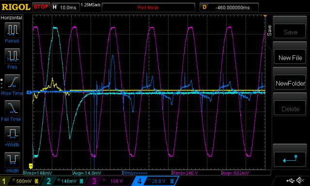 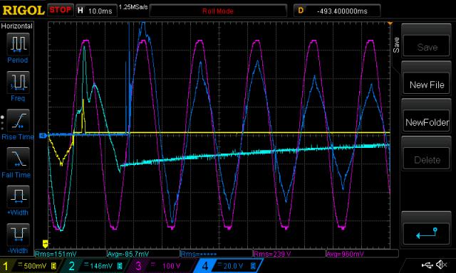 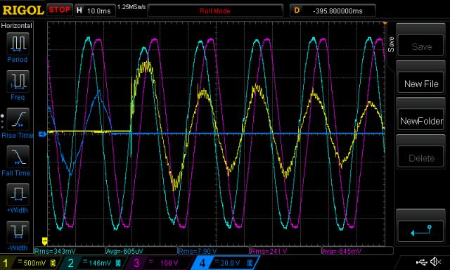 So, I was always wanting to see this, and today I finally got around to it. Maybe this feeds some reader's curiosity, if so, good. wronger than a phone book full of wrong phone numbers |
||||
Madness Guru Joined: 08/10/2011 Location: AustraliaPosts: 2498 |
Nice work, are you use a Toroid or an EI Transformer with this change over? There are only 10 types of people in the world: those who understand binary, and those who don't. |
||||
| poida Guru Joined: 02/02/2017 Location: AustraliaPosts: 1476 |
Madness, the inverter is based on a 3000VA Aerosharp toriod and an Aliexpress 3 x 4 HY4008 mosfet inverter board. wronger than a phone book full of wrong phone numbers |
||||
| noneyabussiness Guru Joined: 31/07/2017 Location: AustraliaPosts: 527 |
Please keep it up... VERY interesting, i always wondered if UPS's etc pll to the grid for changeover (especially the higher powered ones) .. but i can see that not really needed. How you had a chance to check whether a inductive load would be any different, say a fridge compressor? ? I think it works !! |
||||
| Warpspeed Guru Joined: 09/08/2007 Location: AustraliaPosts: 4406 |
A UPS is exactly that, non interrupted, and it absolutely must be phase locked to the grid. Power output must be completely non disturbed and continuous for it to be called a UPS. Only three ways to do that that I know of. In ancient times a rotary UPS used an alternator to supply the load, coupled to a grid powered synchronous electric motor, with a battery powered dc motor on the same shaft. The dc motor could be switched in if the mains failed, and a huge flywheel kept the whole thing going during the momentary switch over. Something a bit more modern, but still in use uses a ferroresonant transformer which essentially does the same thing but without any moving parts. Sola Basic are an Aussie company that have been building those for over a hundred years. I was a design engineer for a while at Sola Basic in Melbourne, and actually designed one of their commercial UPS's. Another way is to constantly run a really big inverter from a grid powered rectifier, backed up with a battery. Pretty much like an off grid system, except the rectifier replaces the solar panels. Anything else is called a momentary break power supply, and its not a true UPS. With something like that there is no requirement for phase locking an inverter. The power goes off for a few tens of milliseconds then comes back on. Its a hard switch over, usually done with relays or contactors and is perfectly adequate for most things. Cheers, �Tony. |
||||
| poida Guru Joined: 02/02/2017 Location: AustraliaPosts: 1476 |
Noneya: The load is a combination of computers, modem, router, 55"LCD TV, 2 fridges, fish tank, and other things mostly on standby. The power factor as measured by the Power Mate is usually 0.6 or 0.8 This is due to running fridge motors, switch mode power supplies etc. It would be easy to check but a pain in the ****. I'd need to go through the house and move all things back over to the street power outlets, then get maybe the bench grinder from work and attach it as the only load. Then re-instrument and test. I am certain there is bi-directional energy exchange between the inverter and loads. When a change over occurs with the loads full of inductive energy, I suppose it has to go somewhere and somewhere is back into the inverter via the full bridge switches and into the bulk capacitors. wronger than a phone book full of wrong phone numbers |
||||
| poida Guru Joined: 02/02/2017 Location: AustraliaPosts: 1476 |
Part 22: Resonant frequency of the toriod/primary choke/secondary winding capacitor Earlier this week Tinyt was looking at the EG8010 startup. When power is applied, the chip outputs 3 pulses at the 23.4 kHz and stops with both outputs of the full bridge pulled to ground. It injects a quick pulse of energy, which excites the resonance of the LC tank circuit (also known as the toriod transformer, series inductor on the primary winding and the capacitor across the 240V output winding) Here is an example, using the 1.95uF cap. 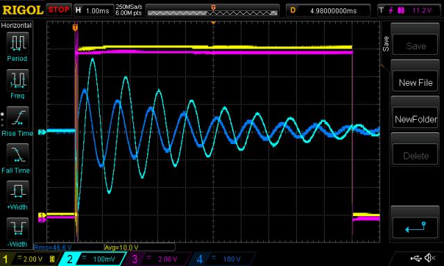 The dark Blue is the 240V secondary voltage. You can easily see the clean oscillation resulting from the short pulse of energy injected into the tank. Light Blue is primary winding current. Yellow is SPWM gate drive. Pink is 50 Hz gate drive. I tried 4 different capacitors and here are the results. 6.45uF gave 461 Hz 1.95uF gave 838 Hz 0.99uf gave 1,180 Hz 0.47uF gave 1,773 Hz The resonant frequency of a LC tank circuit is given as F (hz) = 1/ (2 x pi x sqrt(L x C)) Since the inductance is constant, the frequency varies as 1/sqrt(C) so if we multiply the frequency by sqrt(C) we should get a constant. 461 x sqrt(6.45) = 1170 838 x sqrt(1.95) = 1170 1180 x sqrt(0.99) = 1174 1773 x sqrt(0.47) = 1215 Near enough. The AC output waveforms do change a bit with different caps. In my situation the 1.95uF gives me the least distorted sine wave output and the lowest idle DC current. I mistakenly tried it without any capacitor and the EG8010 could not run at all. wronger than a phone book full of wrong phone numbers |
||||
| Warpspeed Guru Joined: 09/08/2007 Location: AustraliaPosts: 4406 |
There are two different resonant frequencies that we should be interested in here, and both are important if the whole thing is going to operate efficiently as a "system". The first involves a parallel resonance of the transformer secondary and the deliberate tuning capacitor we place directly across it. A second resonance will be a series resonance caused by the series choke in the primary, and the reflected capacitance across the primary. That reflected capacitance back into the primary will be the actual secondary tuning capacitor value, multiplied by the turns ratio of the transformer squared. Now lets think about all this, because getting it wrong can have some pretty unfortunate effects, and getting it right can result in a very sweetly running and efficient inverter that runs with a lower stress. The transformer secondary resonance can generate some pretty fearsome circulating currents, and if it happens to fall on a harmonic, particularly an odd harmonic of 50HZ, then you will very likely see some wiggles in the output waveform, especially at light load. Even without a secondary tuning capacitor, there will be stray capacitance between the secondary and the core, and between layers and turns and it will still have a natural resonance all by itself (somewhere) without any help from extra added capacitance. The series choke in the primary will generate a second resonance, and this can be even more of a disaster because its a series resonance which presents a very low impedance to the mosfet bridge at some unknown frequency. If that unknown frequency coincides with the PWM switching frequency, or even comes close, its going to present a very nasty low impedance load to the bridge. To avoid all these evils, we need to be very careful and go about things in an orderly manner. I will give the solution without going too deeply into the theory. I will take the liberty of using Renewable Mark's inverter as an example. Very first step is to resonate the transformer secondary to 1.5 times the output frequency. 75Hz in Australia (and 90Hz in the US.) The purpose of adding this capacitor is to provide a very high attenuation of the PWM switching frequency. In theory the more capacitance the better the filtering, but as we get down closer to 50Hz we can get a strong resonant buildup of energy which can make voltage regulation very difficult at light load. But the trick is to resonate the transformer at EXACTLY 1.5 times the output frequency, so that any gradual resonant buildup ends up being out of phase with the next cycle. It has a magic self damping effect, and its amazingly effective. But you need to be within one or two Hz to get the maximum benefit. Mark's transformer tuned to 76Hz with exactly 6uF across the secondary. Now we come to the choke. This absolutely must be a non saturating choke with sufficient inductance to limit the peak current flow through the mosfet bridge. The 6uF tuning capacitor across the secondary will reflect back into the primary with turns ratio squared. In this case I don't know the exact ratio of Marks transformer, but I am assuming its about 9:1. So the 6uF on the secondary looks like 81 x 6uF or about 486uF across the primary. Now the choke Mark is using measured as 125uH, and that will be in series with that reflected 486uF creating a very strong series resonance at around 646Hz. That frequency needs to be well above 50Hz (almost x13) and well below 23.5Khz (about 36 times lower) so its well out of the way, and will be harmless where it is. The choke will therefore present a very high impedance to the bridge at the PWM switching frequency, and should work very well. In fact the ripple current at 23.5Khz works out to about 8 amps peak to peak which is fairly low for a full rated load current of 100 Amps. Cheers, �Tony. |
||||
| tinyt Guru Joined: 12/11/2017 Location: United StatesPosts: 559 |
Thanks Tony, it is simple and detailed enough for me to understand now. |
||||
| Tinker Guru Joined: 07/11/2007 Location: AustraliaPosts: 1904 |
Thanks Tony, excellent explanation as always. That 6uF capacitor is way bigger than anything I tried across the secondary. Which got me thinking, on Marks set up that capacitor is on the control board and connected by longish leads out of necessity to the secondary. On my set up that 'tuning' capacitor is right on top of the toroid and connected by the shortest possible leads. Does the lead length make much difference? Intuition tells me yes but I might be wrong. Klaus |
||||
| poida Guru Joined: 02/02/2017 Location: AustraliaPosts: 1476 |
Tinker: I say it's more important which winding you place the capacitor on - secondary winding or primary. You get the (secondary/primary winding ratio) squared times the capacitor value when you place it on the secondary winding. If you choose to put it on the primary you get 1 x capacitor in value. As Tony describes, there are two LC circuits in effect. A parallel and a series circuit. The Parallel LC circuit sees 1 x capacitor in conjunction with the inductance of the secondary winding. The series LC circuit sees the primary choke inductance plus the primary widning inductance combined with the winding ratio squared times the capacitor - if placed on the secondary. If you place the cap on across the primary winding you will need a larger cap to get a good result. wronger than a phone book full of wrong phone numbers |
||||
| Madness Guru Joined: 08/10/2011 Location: AustraliaPosts: 2498 |
I have 6uF also, the 4uF out of the Aerosharp across the toroid output and just one 2uF on the control board. I think Mark copied that from me. There are only 10 types of people in the world: those who understand binary, and those who don't. |
||||
| Warpspeed Guru Joined: 09/08/2007 Location: AustraliaPosts: 4406 |
Everyones transformer will be different, different toroid size, different number of secondary turns, even the batch of steel in the core can make a slight difference. The capacitor Mark was using originally was unmarked, but turned out to be 7uF and that gave a resonant frequency of 65Hz. It was a bit too big. Then we tried 2uF, 4uF and 6uF and the third attempt was right on the money at 76Hz. So its not much use copying what worked for someone else, you are going to have to make the measurement yourself and find out what capacitance your own transformer requires to hit the magic 75Hz number (within one or two Hz). For a battery powered off grid inverter the capacitor is always going to be located across the secondary, because the large turns ratio (9:1 ?)would need a capacitor 81 times as large on the primary to do the same job. A grid tie inverter is different, because it works from a much higher dc input voltage, so the transformer ratio is going to be much closer to 1:1 in many cases, and the capacitor can just as easily go across the primary, which is where you often find it in many grid tie inverters. Just make sure you use a suitably rated capacitor. You can test with any old junk at low voltage to find the optimum final capacitance value. But make sure what finally goes in is going to be up to the job. Cheers, �Tony. |
||||
| poida Guru Joined: 02/02/2017 Location: AustraliaPosts: 1476 |
Part 23 examining output waveform shape as SPWM varies and as AC output frequency varies Up until now, we have built and played with inverters that use a constant SPWM frequency. This is 23.4 kHz when we use the EG8010. My prototype runs at a nominal 20 kHz. Also, our inverters output AC at 50 Hz. I modified the Arduino code to permit any SPWM frequency from about 5kHz up to 40kHz, controlled by a potentiometer. I can change the SPWM frequency while the inverter is running under load, to examine the AC output waveform or primary winding current. I also run code modified to allow the control of the AC output frequency, varying anywhere from 40Hz to 100Hz. I wanted to see how the SPWM filtering went as the frequency was varied. I expected to find some frequency or other which made the inverter go bananas, causing bad things to occur. I have two versions of inverter program running on the Arduino. Version 1 is just like that which runs on the EG8010, it produces a 50Hz fundamental output on one channel and a 20kHz SPWM output on the other channel. Version 2 instead makes a nominal 20kHz sine wave PWM on both channels, one being 180 degrees out of phase to the other. When you feed these two outputs into a transformer, you get the difference which is of course a sine wave. This version has a soft start and a soft stop. I use version 2 in these experiments since it requires twice as many PWM switch events per second compared with version 1, and so it is feeding 2x as much high frequency energy into the transformer/choke/filter system as well. The test conditions are: 27.4 V DC supply 1.95uF filter cap on the secondary 1500VA Aerosharp toriod (0.7 VRMS /turn) with 18 turns on primary, 335 turns on secondary 46uH E core ferrite choke with an air gap (non saturating at my test currents) no load on secondary. � No mosfets were harmed in the production of these videos � First I vary the PWM frequency, from about 5kHz to 40 kHz via a potentiometer by hand. The output AC freq = 50Hz, PWM freq is shown bottom right, in yellow. The primary current is light blue. Notice you can hear the PWM when it comes within audible ranges. video From the video I can say there are no PWM frequencies that lead to catastrophic resonances It just works fine. We see less and less variation in primary current during PWM switching as the frequency goes up and this is to be expected since the freq is rising so the inductor has less energy to store each time. Next I vary the AC output frequency by hand via the pot. The fat trace is primary current (�light blue� but the camera has no exposure control in movie mode..) video 2 At around 40 Hz things are clearly unhappy. Is it due to the parallel LC resonance of the toriod? Idle current has risen to 1.0A, 3x more than normal and you can hear that things are not running well. 40 Hz with 1.95uF cap 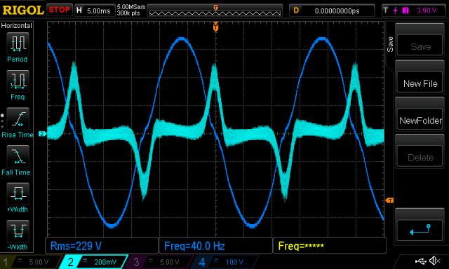 I change the filter cap from 1.95uF to 6.45uF and try again. 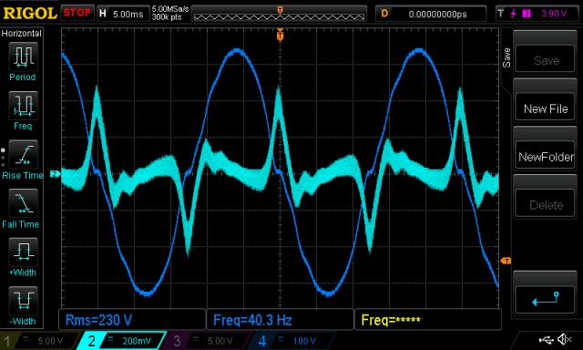 No improvement or change in this bad high current condition. It seems it's not effected by parallel LC resonance frequency - it's due to something else. Idle currents 40Hz (1.95uF) 1.06A (6.45uf) 1.00A 50Hz 0.37A 0.51A 60Hz 0.33A 0.52A 80Hz 0.29A 0.64A Notes: Using faster PWM means more mosfet switching losses but we can use a smaller choke. Increased switching losses are small when I double the PWM frequency so it's quite feasible to use 40kHz PWM to permit a smaller or more easier to build choke. The bad running at 40Hz may be due to my PWM programming, maybe some detail I have overlooked in the Arduino code makes a problem that goes very bad at low AC output frequencies. I doubt it. But more likely I think I have no idea how transformers and PWM full bridges behave so there is most likely some effect happening at 40Hz which will become clear once I study the basics of electronics further. I put the DC clamp meter on the primary, maybe at this freq, the PWM is producing increasing DC current in the primary winding. If so this would be a bad thing. But no, the current remains around 0.3 to 0.4A throughout the 40 - 80 Hz range. I want also to note that I find great value in the education that a simple Aurduino micro controller,combined with a short program, $100 of parts, free parts extracted from a dead grid tie inverter and some time can give. The setup: 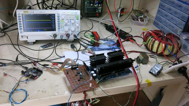 wronger than a phone book full of wrong phone numbers |
||||
| Warpspeed Guru Joined: 09/08/2007 Location: AustraliaPosts: 4406 |
It sounds to me as though your toroid is beginning to head towards saturation as you lower the frequency. The flux swing in the core will be 20% higher at 40Hz than at 50Hz. One way to test this theory, would be to lower your dc supply voltage by 20%. Try running it at 21.9v instead of at 27.4v. See if you can then go down to 40Hz without the current peaking above around 0.5A. Really, forcing it down to 40Hz is rather like performing an unnatural act on it.... But its all in the interests of the learning process. Well done Poida ! Cheers, �Tony. |
||||
| poida Guru Joined: 02/02/2017 Location: AustraliaPosts: 1476 |
I posted this, then went to the pool for a swim. 500m into 1500m I realised it was saturation. I re-did the frequency test but with AC output voltage = 200 V RMS (instead of the above test using 230 V RMS) No ugly things at 40Hz! Of course, it was saturation. Now ugly things happen at 34 Hz @ 200 V AC RMS It's strange though, I see beginning signs of saturation when running this toroid at 50 Hz and 230 V RMS. Not a lot but it clearly reduces as I increase frequency to 55 Hz. It seems there is a little room for further optimisation of the inverters. wronger than a phone book full of wrong phone numbers |
||||
| Warpspeed Guru Joined: 09/08/2007 Location: AustraliaPosts: 4406 |
I have always been trying to urge people to add more turns to their toroids to reduce the flux density. Quite a few Forum members have tried this, and really liked the reduced idling power that it produced. However I was attacked mercilessly by the "Inverter Mafia" for stating this heresy. Apparently, big inverters always must draw big idling currents, because the Mafia Dons have built lots of inverters, dozens of inverters, hundreds of inverters, and all of them draw high idling currents, so this must absolutely be true. Cheers, �Tony. |
||||
renewableMark Guru Joined: 09/12/2017 Location: AustraliaPosts: 1679 |
Lol, Tony, it's a bit of a case of monkey see monkey do. I got too many boards as I anticipated blown boards like when I did the Clockman one, so I can give you a set of boards if you like. Cheers Caveman Mark Off grid eastern Melb |
||||
| poida Guru Joined: 02/02/2017 Location: AustraliaPosts: 1476 |
I take no sides in this dog fight: I am but a lowly experimenter who likes to discover things. But should the things I find and share add to one side or the other, then I am OK with that. Without competing ideas and those who want to support one or another side to the story, most of what we call "scientific progress" would not be possible. Not that I am thinking the 23 and counting posts I have here is to be viewed as science, but. I have complete confidence we all will get to the stage where we can build and repair a multi kW inverter without any fuss and broken semiconductors. Maybe some people here think we are there already and why bother with the details. I mean, there is cold beer in the fridge and it's time to move on... My credo is to keep learning. It's fun and it excites me. wronger than a phone book full of wrong phone numbers |
||||
| poida Guru Joined: 02/02/2017 Location: AustraliaPosts: 1476 |
just like what I am seeing.. saturation from wikipaedia wronger than a phone book full of wrong phone numbers |
||||
| The Back Shed's forum code is written, and hosted, in Australia. | © JAQ Software 2026 |
