
|
|
Forum Index : Electronics : Various aspects of home brew inverters
| Author | Message | ||||
| Warpspeed Guru Joined: 09/08/2007 Location: AustraliaPosts: 4406 |
I am sure you are right. But some of us here are retired professionals that may just have a slightly deeper insight and understanding of all of this, but its a bit discouraging to be met with anger and hostility when only wishing to help people to build a better inverter. Cheers, �Tony. |
||||
| Warpspeed Guru Joined: 09/08/2007 Location: AustraliaPosts: 4406 |
Yes indeed. The story behind all this is that commercial transformer designers are not charitable institutions, they make a living out of building good reliable transformers at absolute minimum rock bottom cost. To do that they come up with a design that uses minimum iron and the minimum copper by pushing the flux density and the temperature rise to the absolute safe (?) maximum. A successful transformer designer will advertise his transformers as having maximum continuous power output at minimum dollars. The buyer never asks about no load idling power, because most commercial transformers go into some kind of equipment that usually draws fairly constant near full rated load power anyway. So a commercial inverter designer is pretty much in the same boat. The transformer in his inverter will almost certainly be the most expensive single part, and he is trying to compete with other inverter manufacturers, and still make a profit. Very often idling power is not even included in an inverters specifications, and that is deliberate. For something like a grid tie, it probably does not matter much anyway. But if you are off grid and on a battery, no load power suddenly becomes of critical importance. Now we are in a VERY different situation to the commercial inverter people. We are winding out own transformers, often out of free or recycled junk. We don't care about how big or heavy it is, or how much the core or the wire costs brand new. We want to make something really nice that performs much more efficiently than some corporate bean counter scrooge would ever allow. So just reverse engineering or copying commercial designs and thinking that must be the absolute ultimate is a very big mistake. We can do very much better than that if we apply some well known theory and design our own transformers from scratch to do what we want it to do. Transformer design has been perfectly understood for over 200 years. Micheal Faraday solved all of the design equations back in the age of sailing ships, muzzle loading guns and crude steam engines. There are no mysteries, its not voodoo or magic. Cheers, �Tony. |
||||
| Tinker Guru Joined: 07/11/2007 Location: AustraliaPosts: 1904 |
I did some experimenting with this today. The toroid came from a 2.5Kw Latronics LF inverter, I re used the original 230V winding. All was hooked up as suggested but I was handicapped by my audio oscillator which had a rather course frequency adjustment. It could be set to 50 or 75Hz with a bit of knob fiddling. I tried that little kit digital oscilloscope first, too small screen to notice amplitude differences accurately. Then I connected my analogue CRO, this was better but it is still hard to see just exactly where the peak occurred. So a different approach was used. I have a multimeter which can measure AC RMS values. Turning the oscillator amplitude down so it remained below 2.000V at peak resonance it was very easy to see just where this peak was. A few millivolts difference where shown when one Hz above or below resonance. Its not a sharp peak which is why I found it hard to see on my old CRO. It corresponded with what I saw on the CRO but was much more precise. The frequency was monitored on another multimeter, there is no scaling on my home built audio oscillator. Interesting results with this toroid, a 1uF cap resonated well below the optimal 75Hz. 2 x 0.47uF in parallel gets closer. 0.47 & 0.33uF in parallel was just about spot on. As Tony mentioned, different toroids behave quite different. It would pay to have a selection of mains rated caps on hand for this test. BTW, it appears no fancy oscilloscope is required as the RMS multimeter seems to do a better job. Perhaps just monitoring the frequency on the little kit oscilloscope to see if all is running sweetly. Klaus |
||||
renewableMark Guru Joined: 09/12/2017 Location: AustraliaPosts: 1678 |
I have a question, If an inverter like the Ozinverter ran fine with a small choke that did indeed saturate at higher loads, would that inverter be prone to a failure under certain conditions and not others. IE different loads, what would be the worst case scenario? BTW Tony, I wouldn't take it personally, I told someone to "shut up" the other day, he didn't take it well and really had a sook about it big time, but I didn't mean it to be harmful. Sorry to get your thread off track Poida  Cheers Caveman Mark Off grid eastern Melb |
||||
| Warpspeed Guru Joined: 09/08/2007 Location: AustraliaPosts: 4406 |
Klaus, The peak can definitely be difficult to see very accurately, but its there somewhere. One thing to be rather careful of is that you are not tuning the transformer to a harmonic of 75Hz. With the oscilloscope peaking at a harmonic of 75Hz (say at 150Hz or 225Hz) may result in lower peak, with an odd lumpy looking waveform. With a multimeter you don't get the same visual clues of waveform distortion that there will be with an oscilloscope. The signal generator may be tuned to 75Hz o/k, but there might be a visible peak at one of the signal generator harmonics which might lead you astray, and its fairly easy to get caught that way. That 1uF does sound rather small which is a bit of a concern. One way to be more certain is to tune the signal generator over a much wider frequency range, especially much higher, to make sure you settle on the largest real peak there is. Then use the multimeter for finer final measurement. Mark, A saturating choke (or having no choke at all) means that the bridge will be switching straight into a highly capacitive load which can produce some very high peak currents in the mosfets. Definitely not recommended. Anything that make the inverter operate in a higher stress mode can certainly make it more vulnerable when other external load extremes are also applied to it. That double Aerosharp choke with the twelve turns will work fine without a ferrite choke. Adding an additional ferrite choke may help very slightly with idling current, but that will saturate beyond a medium load, leaving the big iron choke to do the job which it will do with ease. By the way, I think your iron choke has about 3 metres of that 25mm squared wire on it. You might correct me on that. I remember you clearly marked off the length, but not sure what that measurement was. Anyhow 3 metres works out to 0.0172ohms x 3 metres divided by 25mm squared = .00206 ohms. At 100 amps that will drop 0.206 volts, less than half a percent of 48v. If you tried really hard you might get 50mm squared worth of stranded copper wire onto that choke, and gain a quarter of a percent. Its just not worth worrying about. The transformer primary on the other hand, really needs all of that that 70mm squared because the wire length in the primary is much greater than in the choke. Cheers, �Tony. |
||||
| johnmc Senior Member Joined: 21/01/2011 Location: AustraliaPosts: 282 |
Good Day poida, Thanks for your topic and your effort, this information that you have shared, has been a great help. AS you know, I have almost perfected the art of destroying Fets, PCB's and all associated parts for the inverters except the transformer. Yet I find this topic most informative, and in a strange way addictive. cheers john. johnmc |
||||
| Tinker Guru Joined: 07/11/2007 Location: AustraliaPosts: 1904 |
Tony, I'm sure your CRO is way better than my 20+ year old dual trace BWD job. Watching for tiny amplitude changes of a none to stable trace (can't slow the timebase too much or I get intermittent trace bursts) is not easy at all. I did wind up the frequency to over 200Hz and back down several times, the only amplitude increase was at 75Hz with the selected capacitor. Any bigger caps gave that peak at much lower frequencies. But I will test for your harmonics suggestion tomorrow. Might write it down as a list for each different cap sizes and test to over 200Hz for each. BTW, I did not notice any "distortion" of the sine wave at the resonance peak, just an amplitude change. I do remember from trade school way back the very distinct peak of a parallel resonance but that was at a very much higher frequency and smaller coils. You could easily try my multimeter trial at your place, I cannot try your precision oscilloscope method due lack of good enough equipment. Lets see what you find out. Klaus |
||||
| Warpspeed Guru Joined: 09/08/2007 Location: AustraliaPosts: 4406 |
Its getting late here now, but tomorrow I will give the multimeter method a try. We are not that far above 50Hz, so just about any multimeter should work quite well for this method. You might like to try higher values of series resistor. That will drop the amplitude, but may very slightly sharpen up the peak. Probably will not make much difference, but worth a go. All this is easier with good test equipment, but it becomes much more difficult trying to improvise. Cheers, �Tony. |
||||
| Warpspeed Guru Joined: 09/08/2007 Location: AustraliaPosts: 4406 |
Poida, What is the origin of that transformer you are testing with ? I have seen some pretty extreme cases where an American sourced transformer originally designed for 220v 60Hz, often located inside a piece of equipment, has been used at 240v 50Hz and has subsequently failed due to saturation causing the primary to overheat and eventually burn out. Cheers, �Tony. |
||||
| poida Guru Joined: 02/02/2017 Location: AustraliaPosts: 1432 |
Warpspeed, the transformer is a 1500VA Aerosharp. I measured it at 0.715 V AC RMS/turn at 230 V AC RMS on the secondary winding. It has a label on it, with the secondary rated at 230V and 4.3A. The primary winding is not much use to me, it's marked as 93V 50/60Hz.... So I suppose it's good for 50Hz. At about 235V RMS it shows clear signs of saturation at 46Hz. I found a good way to see when saturation is/isn't. I place a current sensor on the DC supply and watch for the peaks to appear that correspond to the AC voltage zero crossing. I can get it to about 1/2 Hz. pink trace is DC supply current light Blue is primary current dark Blue is AC output voltage no saturation: 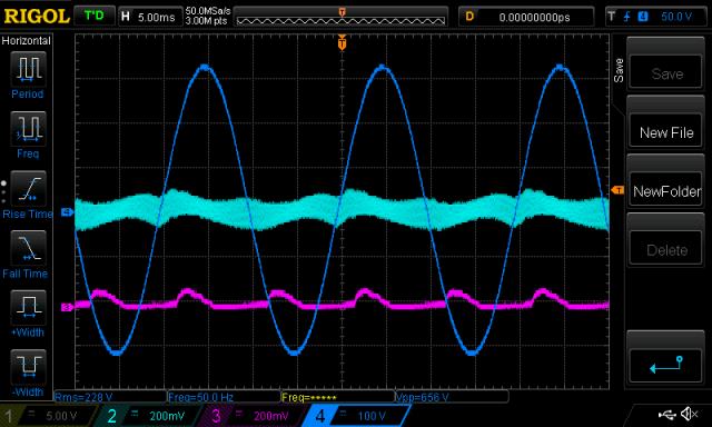 arrows show the beginnings of saturation: 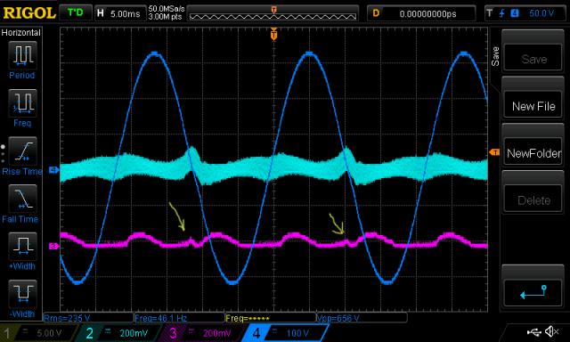 wronger than a phone book full of wrong phone numbers |
||||
| Tinker Guru Joined: 07/11/2007 Location: AustraliaPosts: 1904 |
Today's results: 1st column = 0.47//0.33uF 2nd = 0.47//0.47uF. It appears the forum deletes the spaces I left between the columns, I hope you can make it out. I deliberately set the amplitude below 2 Volt as that gave me 1.000 accuracy. 40Hz 1.847V 1.885V 50Hz 1.922 1.939 55Hz 1.936 1.939 60Hz 1.946 1.946 65Hz 1.952 1.948 70Hz 1.955 1.947 75Hz 1.956 1.942 80Hz 1.953 1.936 85Hz 1.949 1.936 90Hz 1.943 1.916 100Hz 1.927 1.888 120Hz 1.883 1.823 150Hz 1.794 1.705 180Hz 1.692 1.579 I also did this test with 1uF & 2uF capacitors. 1uF had the peak at 65Hz, 2uF below 40Hz. Klaus |
||||
| Warpspeed Guru Joined: 09/08/2007 Location: AustraliaPosts: 4406 |
That seems like a rather low and flat peak Klaus. Try it again with a much higher value series resistor. I just went out to the shed and grabbed an inspire toroid which only has the 130v primary winding on it, and a 5uF. Quickly measured it with a multimeter and a 1K series resistor at 20Hz intervals. I had no idea where the peak was going to end up... 20Hz 258mV 40Hz 659mV 60Hz 977mV 80Hz 863mV 100Hz 706mV 120Hz 585mV 140Hz 493mV 160Hz 424mV 180Hz 368mV 200Hz 323mV Looked at the whole thing on my brand new (thirty+ year old) antique spectrum analyser measured the same way, 1K series resistor, 20Hz per horizontal division, linear vertical scale. There is a clearly defined peak at about 62Hz, and its reasonably sharp too. 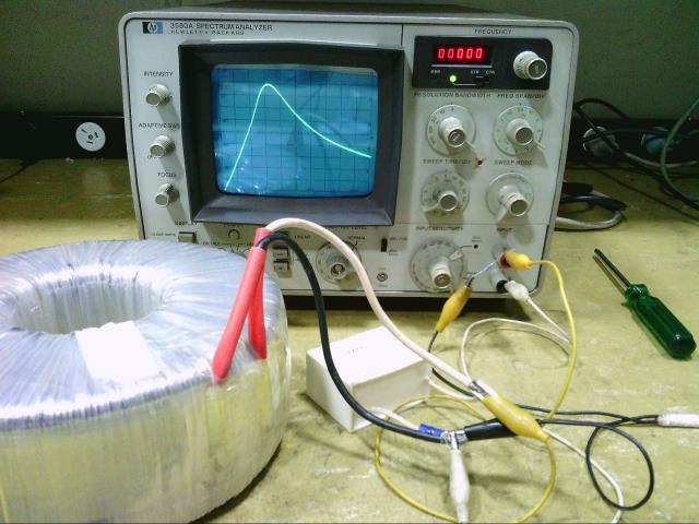 Cheers, �Tony. |
||||
| Tinker Guru Joined: 07/11/2007 Location: AustraliaPosts: 1904 |
Sorry poida if I keep hijacking your thread but it -is- one aspect of a home brew inverter  . .A question for warpspeed; having trouble resonating my 2.5KVA toroid secondary with a suitable capacitor I thought of a different approach - solving it mathematically. I found this calculator on the net. It lets me input two known parameters and calculates the third of the parallel resonance formulae. I measured my toroid secondary as being 575mH, using that little LC tester that was mentioned here some time ago. For 75hz resonance it comes up with 7.8316uF Assuming I use a 8uF capacitor the resonant frequency would be 74.2Hz Does that look all right by you? I'll try a 8uF motor start cap tomorrow and see if the audio oscillator method gives a sharper peak with that. Klaus |
||||
| Warpspeed Guru Joined: 09/08/2007 Location: AustraliaPosts: 4406 |
I use that exact same calculator all the time, have it bookmarked. Difficult to know for sure Klaus, but Mark's secondary needed 6uF. My gut feeling is telling me that 8uF sounds a lot more plausible than 1uF. Its going to vary quite a lot, because all our big transformers are fairly unique. But 1uF just does not feel right. Cheers, �Tony. |
||||
| poida Guru Joined: 02/02/2017 Location: AustraliaPosts: 1432 |
Part 24: thermal thoughts We are making (and breaking) inverters built using HY4008 mosfets. Typically we have 3 or more, up to 6 of these paralleled on each of the 4 legs of the full bridge. I was interested in how well heat is removed from the chip, via the TO-247 package and into the heatsink. I have built and abused, Royally, a very handy DC constant current load. It senses drain to source current and drives the fet gates to maintain a desired DC current. 2 mosfets share the same gate drive. It works fine and I love it. It uses NEC K3304 mosfets I pulled out of a dead plasma TV. These are in a TO-3P package, similar to the TO-247. This toy handles 120W continuous and 1 minute pulses over 150W with ease. Under load the 2 K3304 fets dissipate all the heat and transfer it to the heatsink. I have found on numerous occasions the heatsink is hotter than the front of the TO-3P package, to my calibrated finger. Much hotter. This is good, it shows the heat is being conducted well, away from the chip and to the back of the package. 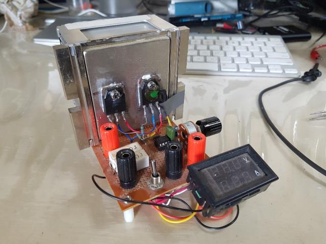 I was wondering one day how our favourite MOSFET goes, in this situation. So I made a test DC load, able to drive 2 mosfets with independent gate drives that maintain the desired current. The test load: 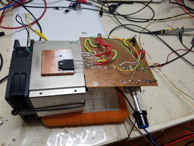 First, I used one gate drive for 2 mosfets but always one or the other fet would heat up and take all the load. The Gate threshold voltage is variable with these devices. SO I built 2 current sense, gate drive circuits, to prevent one fet taking all the current. Anyway, the Hy4008 in TO-247 package is in my experience poor at conducting heat to the heatsink. You can easily feel a hotspot appear on the front of the case, then the heat sink warms a little, then the hotspot gets hotter and hotter. Always the heatsink stayed quite a bit cooler than the front of the case. I swapped the Hy4008 for the NEC K3304. Immedately I could feel the heatsink get hotter BEFORE you could feel heat on the front of the case. The difference was surprising. I tested this at 30V and 2 amps in both cases. I also have a bag of TO-220 packaged HY4008. I tried the same and got the same result of a much hotter front of the package compared with the heatsink. So what's all this got to do with the price of fish? Hooyi Semiconductor provide specs for their chips and one I found interesting is max continuous current This is 200 A at 25Cj (at the chip junction) and 153 A at 100Cj and max power 397W at 25Cj and 199W at 100Cj In testing I have blown these HY4008 with as little as 5A, when attached to a heatsink. Easy, just supply 30V at 5A and that's 150W. I did not power it for long, just 1 second, the time needed to twist the power supply current limit knob. The TO-220 packaged HY4008 are less capable of conducting heat and break easier. I didn't get to 5 amps before it failed. I started it cold, with a good heat sink compound under it. less than a second ramping it to 5 amps kills the fet with a 30V supply. It dies well before 150W and these are rated at 173W at 100Cj. The junction must heat up very quickly and not conduct heat to the case. The de-rating curve shows 100W max at 130C. I suspect Hooyi have designed these chips in a way that they have poor heat conduction from the chip junction to the case. My views on using these in our inverters: they are cheap. they work. I have no idea how they continue to work. Do not use them unless they are fully switched ON or OFF. When used in the saturation area, they are very weak devices. DO NOT let them get hot. ** MOSFETS were harmed in the preparation of this article. wronger than a phone book full of wrong phone numbers |
||||
| renewableMark Guru Joined: 09/12/2017 Location: AustraliaPosts: 1678 |
The front isn't conductive, would clamping a copper/aluminium bar across the front help? Cheers Caveman Mark Off grid eastern Melb |
||||
| johnmc Senior Member Joined: 21/01/2011 Location: AustraliaPosts: 282 |
most interesting, thanks poida , for the insight. Are we taking about two different application one pulsed current and the other DC. The fets in a 6kw inverter with 6 fets per leg must at times see large currents  . .cheers john johnmc |
||||
Madness Guru Joined: 08/10/2011 Location: AustraliaPosts: 2498 |
Great work Poida, what gate voltage were you using? There are only 10 types of people in the world: those who understand binary, and those who don't. |
||||
| Tinker Guru Joined: 07/11/2007 Location: AustraliaPosts: 1904 |
I'm doing just that on my experimental inverter. I call it the mad bar as he came up with that idea. Mine is 20 x 3 mm alu bar long enough to cover all the mosfets on each individual heat sink. Perhaps Poida can try that idea with his test rig and see if it makes a difference to the front heating. It certainly does a good clamping job. Klaus |
||||
| poida Guru Joined: 02/02/2017 Location: AustraliaPosts: 1432 |
nope. The chip is supposed to be thermally very well connected to the metal plate on the back. The idea is to use this metal plate to convey all the heat away from the device. I am starting to think HY4008 are not so well thermally connected to the metal plate of the package. wronger than a phone book full of wrong phone numbers |
||||
| The Back Shed's forum code is written, and hosted, in Australia. | © JAQ Software 2025 |
