
|
|
Forum Index : Electronics : Various aspects of home brew inverters
| Author | Message | ||||
| gaspo Regular Member Joined: 25/06/2018 Location: AustraliaPosts: 67 |
Poida, I'm not sure if I see what you describe - the 50% duty in stop mode. I see the following constantly varying length pulses 100-500ns. I did not check the other code samples you've provided, only the last one. 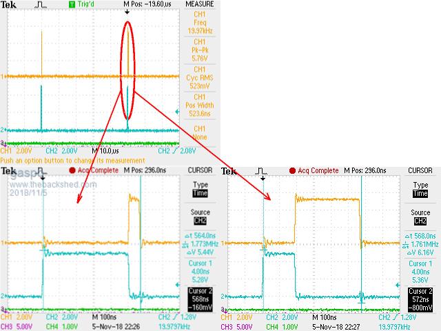 |
||||
| Tinker Guru Joined: 07/11/2007 Location: AustraliaPosts: 1904 |
All this sounds very interesting, unfortunately I'm not quite at a level to understand it all. But curiosity prompts me to ask this silly question: What difference does the feeding of two 50Hz sine waves into the mosfet gate drivers make instead of 50hz square wave & 20KHz SPWM? I recall you mention that mosfets do not like being turned on slowly - or am I misunderstanding something here  ? ?Klaus |
||||
| gigabyte091 Newbie Joined: 15/10/2018 Location: CroatiaPosts: 17 |
So here are some waveforms when the ardruino is loaded with first program: When program is not running (top waveform is filtered through 4k7 and 10n RC network) 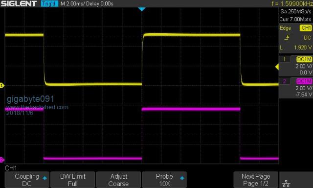 And there is picture when is running: 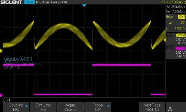 Your idea for LCD screen is great, it would be nice to have basic parameters displayed on screen, i think amps, volts, and hertz is more than enough, so you can use 16�2 LCD where top row could display these parameters, and botom row could display system informations such as inverter running and fault codes. Which protocol are you planning to use for display ? I2C or SPI ? Im looking forward to see program version with OCP and maybe OTP. @gaspo here i tried to reproduce your waveforms and with edge triggering i didnt manage to get stable waveform, duty cycle was all over the place, and then i use pulse triggering and manage to get stable waveform 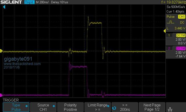 I left my trigger menu opened so you can see what settings i used |
||||
| poida Guru Joined: 02/02/2017 Location: AustraliaPosts: 1480 |
Tinker, I think you will have no problem working out what I am doing with this 2x sine version of the code: To understand what is happening, first start with the 2 1/2 bridges we use already, with the 2 outputs (I term V1 and V2) connected to the transformer primary, with a choke in series to help filter out the PWM noise. The EG8010 produces a 50Hz square wave on V1 and SPWM on V2. By cunning arrangement of the SWPM (inverse sine 1/2 waveform, normal for the other half) we get what we want, which is a sine wave of 50Hz at V1-V2. It is important to always look at the difference between V1 and V2. That is what the transformer sees. In my 2x sine code, I do it differently. On power up, I produce a DC voltage on V1, and the same DC voltage on V2. It is nearly exacty 50% duty cycle. I look at this state as having two DC-DC converters running, each making a DC voltage appear at V1 and V2. Since they are the same voltage, no current flows. When the enable button is pressed, my code starts to ramp up the power demand variable, increasing 1/300th of full scale each 1/100th of a second. We might get to full power after 3 seconds. The power demand variable is used to make the DC voltage - which has until now been kept constant - to follow a sine wave with it's amplitude controlled by this power demand variable. So now we have an AC and a DC component present on V1 and V2. My code makes the AC component be 180 degrees delayed on V2 compared to V1. So when the transformer sees the voltages of V1 and V2, it sees only the AC component. This approach creates just about exactly 2 x the switching losses in an inverter, compared with the EG8010 approach. I did this work to explore switching losses and figured that I could double them with a bit of new coding. Of course I did not need to change anything on the inverter MOSFET bridge board. I'm not turning on slowly the MOSFETS as in my heat tests. Not at all, I'm switching them quickly, as usually done by everyone else here. I made a video for you. Yellow is arduino output for V1, light Blue is output for V2, purple is the 50Hz sync pulse used to get a stable DSO trigger. At top is about one complete 50Hz waveform. At bottom I zoom in to the top of the 50Hz AC waveform where we can see the maximum difference in duty cycle (of V1 and V2) Think of duty cycle as being equivalent to 1/2 bridge DC output voltage. The video shows standby (both V1 and V2 same DC voltage) I press the start/stop button and so it ramps sine wave amplitude up to 230V AC output. Then I press start/stop again and it ramps down to zero output. have a look at https://youtu.be/L6i5yOFxR2k wronger than a phone book full of wrong phone numbers |
||||
| poida Guru Joined: 02/02/2017 Location: AustraliaPosts: 1480 |
Gaspo: I'm not sure how you are getting these signals. Just to make sure we are both on the same page we need to be both using the same type of Arduino and looking at the same pin's outputs. I am using the 2x sine code, loaded into an Arduino Uno. The code requires two timers to be present, and we use the output compare function to drive pins 9 and 10 from TIMER1. We need access to OC1A and OC1B for this function. If you are using an Arduino that has a different chip than an ATMEGA 328p then we probably will see different results. All the codes posted by me require an ATMEG 328p uC and it's simple and cheap to get them from ebay at $10 each when you buy a "UNO board". I see from a prior post that you are using a "pro-mini" This uses the ATMega 328. here is the pinout: 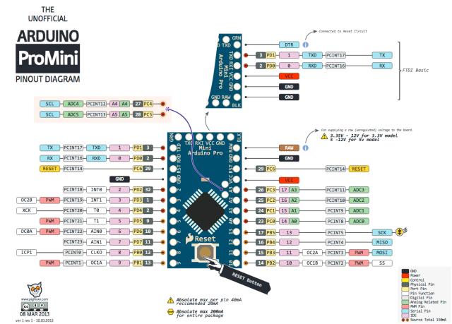 I see pins 9 and 10 are connected to OC1A and OC1B. This is good. Make sure you feed it 5V so it runs at 16Mhz just like a Uno. The video I posted for Tinker shows outputs on 3 pins. Pins 9 and 10 are Yellow and light Blue. (OC1A and OC1B) The Purple trace is pin 7. This pulse is the result of the following: .. if(pcount >= NPWM) { pcount = 0; sbi(PORTD,7); // give a sync pulse for DSO, alligned with start of 50Hz cbi(PORTD,7); } .. wronger than a phone book full of wrong phone numbers |
||||
| poida Guru Joined: 02/02/2017 Location: AustraliaPosts: 1480 |
Part 25: How I log, process and view the data from my solar power system I have enjoyed home brew solar power since about 2015 or earlier. I can�t recall when I first set it up since it�s come to the stage where �we�ve always had it working here� Along the way I have further developed my programming skills and added new languages to my skill set. This system uses html, php, javascript and C. Anyway, some basic facts: 48V battery, 400Ah. one 3kW array, of 250W panels. Wried in 4 parallel x 3 in series, facing North. another array, 3kW of 250W panels, 6 parallel x 2 in series, facing East. An MPPT controller, taking the North facing array. This gets up to 100V input, DC-Dc converting to suit the 48V battery. A PWM controller, taking the East facing array, This gets up to 60V and 20A and is nowhere the 3kW rated. A Raspberry Pi computer, running things. Powered by a DC-DC converter connected to 48V battery. An Arduino Nano, connected to the Pi, powered by the Pi. A change over relay (Latronics ACTS40) which powers part of the house, using either inverter supplied AC or street power. This changes over automatically depending on the availability of inverter power. 1/2 of the house is connected to this circuit via an RCB, and it's properly earthed, wired with 1.5mm2 3 core under the house, leading to numerous GPOs. Thermistor temperature sensors, attached to battery terminals. A DC current sensor, +/- 60A or more range. The mppt controller is a Morningstar 60A ppt. It comes with internet connectivity. I request the device�s operating parameters every 2 minutes. From an http request such as �http://172.16.0.54/MBCSV.cgi?ID=1&F=4&AHI=0&ALO=27&RHI=0&RLO=36� I obtain the battery voltage, charging target voltage, charge current, array current, array voltage heat sink temp, battery temp, charge state, ppt sweep max power, sweep open voltage and more from the device. The PWM controller is a Morningstar 60A Tristar. No internet connection alas. But it has a serial port. Via a RS-232 to usb cable, into the Raspberry Pi I can send and receive Modus data. And so I obtain the Tristar�s battery temp, voltage, charge current, heat sink temp. The Arduino nano is used to obtain the current draw by the inverter, and convert to an integer. It also counts pulses obtained from the infrared sensor located on top of the 1 watt.hour pulse LED of the house�s smart meter. This gives me street energy consumption. So the Raspberry Pi knows all, every 2 minutes. It comes with sufficient storage for a database. I use and recommend mysql as the database. Every 2 minutes a new record is inserted into the table named �datah� The table is organised thusly: mysql> describe datah; +--------------+------------------+------+-----+-------------------+-----------------------------+ | Field | Type | Null | Key | Default | Extra | +--------------+------------------+------+-----+-------------------+-----------------------------+ | id | int(10) unsigned | NO | PRI | NULL | auto_increment | | bv | double(6,2) | YES | | NULL | | | tv | double(6,2) | YES | | NULL | | | ts | timestamp | NO | MUL | CURRENT_TIMESTAMP | on update CURRENT_TIMESTAMP | | cc | double(6,2) | YES | | NULL | | | av | double(6,2) | YES | | NULL | | | ac | double(6,2) | YES | | NULL | | | op | double(6,2) | YES | | NULL | | | svmp | double(6,2) | YES | | NULL | | | swoc | double(6,2) | YES | | NULL | | | swpm | double(6,2) | YES | | NULL | | | bt | int(2) unsigned | YES | | NULL | | | hst | int(2) unsigned | YES | | NULL | | | chargestate | int(2) unsigned | YES | | NULL | | | ledstate | int(2) unsigned | YES | | NULL | | | ddate | datetime | YES | MUL | NULL | | | dtime | datetime | YES | | NULL | | | loadamps | double(6,2) | YES | | NULL | | | streetpower | double(6,2) | YES | | 0.00 | | | meterwhr | int(2) | YES | | NULL | | | inverterctl | int(1) | YES | | NULL | | | lvcomp | int(2) | YES | | NULL | | | tscc | double(6,2) | YES | | NULL | | | tshst | int(2) | YES | | NULL | | | loadampspeak | double(6,2) | YES | | NULL | | | tsbv | double(6,2) | YES | | NULL | | +--------------+------------------+------+-----+-------------------+-----------------------------+ I can extract records from this table satisfying various criteria. e.g. to get all the records, sorted by time for the day 2 Nov 2018 the query would be �select * from data where ddate = 20181103000000 order by id� Right now we can see how today�s situation is going. It�s rather cloudy so things are very up and down. 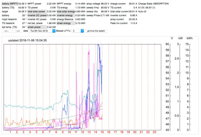 I welcome all to have a play with this. http://poidapie.chickenkiller.com/mppt/c19d.php I control the inverter myself, some inverters have low voltage cut off controls and more. I do it via digital output of a Raspberry Pi pin, onto isolated, then driving a mosfet to pull down anything up to 60V to ground as a control output. MY home made inverters only need a low current 12V signal to be pulled to ground. The Powerjack LF inverter needs to have a battery voltage level signal pulled to ground. That�s why the mosfet is utilised. Every 2 minutes I insert a new row of data, check the battery voltage against limits and drive the inverter control as needed. The Raspberry Pi has a web server running, and this serves up requested pages. I have progressively developed the web page that generates the above image over the past few years, on and off. Programming the Arduino nano is done via the Linux console on the Raspberry Pi using Platformio. I can reprogram the nano remotely from work if I like. It's all very flexible with remote administration. We only have ADSL here at home and that places limits on how fast I send data out of the house. This has been a welcome challenge for my programming, to drive efficient coding that works over slow connections. I do IT for a living so network setup is easy. I have the Raspberry Pi web server available to the internet, contactable by anyone, anywhere. Should the advertising of my webserver become a problem I can easily limit access to certain locations such as my workplace and home. Control of this is absolutely no problem at all. 2018-11-06_143433_untitled_folder.zip Simple mathematics is all that is needed. Given DC voltage and DC current we can get DC power just from multiplying. To get energy, you total up the power times 2/60 (giving watt.hours) over the required time interval when samples occur every 2 minutes. Here is the energy consumption of the house from 2016 to date: Some energy comes from the street, some from the inverter. 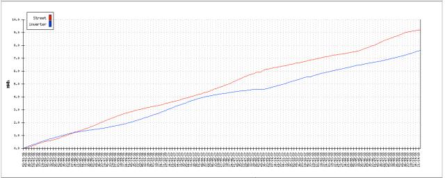 And the daily energy consumption: 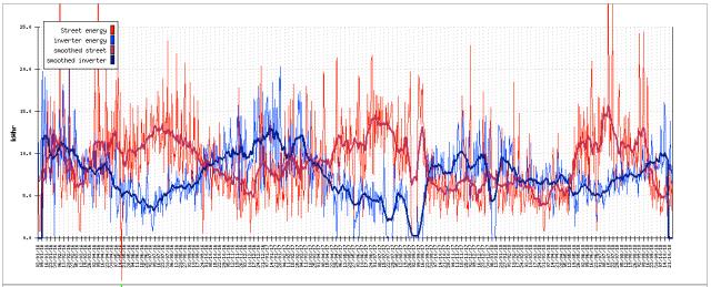 There were 4 weeks when I did not have a working inverter. Talk about anxiety or what... I attach all the various programs and web resources needed to make my system work and am happy to answer any questions anyone here wants to ask. wronger than a phone book full of wrong phone numbers |
||||
| Tinker Guru Joined: 07/11/2007 Location: AustraliaPosts: 1904 |
Thank you poida for your comprehensive reply. It is an interesting approach you created there,to coax a 50Hz sine wave into the primary. I shall follow this topic with interest and might even rustle up the courage to start tinkering with the arduino I bought a while ago (after madness suggested its usefulness). Writing programs is a bit beyond me since that art progressed past basic language  but I should manage to program what you and others so kindly post here. but I should manage to program what you and others so kindly post here.So the idea is to replace that EG8010 adapter board with an arduino based version which can be tailored to requirements. How durable will that then be afterward, when used in a working inverter? Will it be just plug in and let run as the EG8010? Considering one would want a spare board to minimise inverter down time should something go awol in that electronic brain. I can even see an opening for somebody to supply plug in adapter boards for those (like myself) not having much programming skills. At the moment I'm working on an opto isolated driver board which would be removable from the power board where the mosfets, etc. reside on. The drivers are optically interlocked (as per warpspeed) to prevent cross conduction. Another big advantage with this is the control board can be located a fair way off since its output is current based. It would be easy to re do my control board so it can accommodate the sine wave generating arduino. Perhaps we can come up with a truly bullet proof inverter - or is this wishful thinking .Klaus |
||||
| gaspo Regular Member Joined: 25/06/2018 Location: AustraliaPosts: 67 |
Poida, yes the pro-mini is using the same 328P chip as Uno. I have Uno as well and the code behaves the same. By looking at the code in uno_inverter_2x_sinewave_pwm.ino it seems that what I observe on pins 9/10 in stop mode is correct. When you stop inverter it decrements sst to zero while gradually reducing the pwr factor to a minimum value of 0.01. When sst == 0 the code clears pin PD5 (driving /SD on IR2184 low?). The TIMER1_OVF ISR keeps running trying to produce SPWM duty using the minimum power 0.01 (vpwr). Because calculated duty written to OCR1A/B is not zero I see very narrow 100-600ns pulses. But that does not matter if the IR2184 is disabled when stopped. I like your inverter code, how simple and stable it is while utilising the PID and the LP filter on analog pins. |
||||
| gigabyte091 Newbie Joined: 15/10/2018 Location: CroatiaPosts: 17 |
There should be no problem to make new boards, all you need to add is new mosfet drivers, perhaps some signal isolation (optocouplers) so we can isolate power electronics from logic and some fan control which you can easily make with few components. I will try to buy tommorow some drivers and complete test inverter. |
||||
| tinyt Guru Joined: 12/11/2017 Location: United StatesPosts: 561 |
I also can confirm the presence of pwm pulses in stop mode. I have seen this before in my other projects using atmega pwm. Even though the compare value is zero, there will be one timer clock pulse at the compare output pin(s) every overflow. What I did is disconnect the compare output from the port pins. So in the code, this change worked for me: cbi(PORTD,5); cbi(DDRB,1); cbi(DDRB,2); // change direction to input, disconnect output compare(s) } else {sbi(PORTD,5); sbi(DDRB,1); sbi(DDRB,2);} // restore direction to output The change is not needed since the SD of the IR2184 is already being used. |
||||
| poida Guru Joined: 02/02/2017 Location: AustraliaPosts: 1480 |
Gaspo: I have been running a different code than you! That is why you see something I do not. Sorry to waste your time. I am running the vf_output_freq code right now. This has the 50% duty cycle when stopped. That is what I used in the video https://youtu.be/L6i5yOFxR2k when illustrating how these programs work. The 2x sinewave pwm code you are running is different to the above... I just loaded the 2x sinewave pwm code and it does exactly what you have shown. These narrow pulses are no problem due to approximately 500ns dead time from the gate drvie ICs. The MOSFET gates see little or no drive with these narrow pulses. I like Tinyt's fix. I'm not sure it's required but it seems to be a safe way to clean up the drive narrow pulse signalling. wronger than a phone book full of wrong phone numbers |
||||
| poida Guru Joined: 02/02/2017 Location: AustraliaPosts: 1480 |
I post the code here so anyone who wants to use it, hack it and improve it can do so. The Arduino shield board I hacked up has output pins arranged in a way to duplicate the EGS002. I can change from my Arduino drvier to an EGS002 without any configuration changes. Please note: The EGS002 needs to have the opamp removed and a trace cut (permitting the IR2110 shutdown pull down resistor to pull down permanently) for reliable running. In other words, I disable over current cut off completely. Awesome! Let's see if it works. wronger than a phone book full of wrong phone numbers |
||||
| poida Guru Joined: 02/02/2017 Location: AustraliaPosts: 1480 |
Here is a video of standby - slow start - full power - slow stop - standby of the 2x sinewave pwm code Yellow is V1 Blue is V2 Purple is (V1 - V2) which is what the transformer sees. https://youtu.be/5sSjQ0vPmlg Notice all traces are DC coupled. i.e. we see the DC voltage. wronger than a phone book full of wrong phone numbers |
||||
| gaspo Regular Member Joined: 25/06/2018 Location: AustraliaPosts: 67 |
Not a problem  I realised that once I loaded your other code samples and I saw 50% duty in the stop mode. The time was not wasted, it helped me to better understand how your code works. As I have few spare STM32F042's I'll port the inverter code to run on them. |
||||
| poida Guru Joined: 02/02/2017 Location: AustraliaPosts: 1480 |
That sounds interesting. Please share the code here so I can learn about the STM32. What IDE or tool chain are you using? Could I try and find a cheap STM32 ? maybe this ebay cheapie will be close enough to run the code you develop? wronger than a phone book full of wrong phone numbers |
||||
| noneyabussiness Guru Joined: 31/07/2017 Location: AustraliaPosts: 527 |
stm32 Poida, these are cheaper, very similar and can be programmed with arduino ide.. They are 3v though.. stm32 forum Stm32 arduino support forum I think it works !! |
||||
| gaspo Regular Member Joined: 25/06/2018 Location: AustraliaPosts: 67 |
Poida, you can go Arduino way as noneyabussiness suggested. It will get you going fast with familiar library functions. It took me less than 20 minutes to get the blinking LED program going. Here is the list of supported STM32F103 boards. For Arduino development I use VS Code with Arduino add on, mostly because it offers intellisense. I have that STM32F030 development board. I used it over a year ago to learn STM32. I went the hard way using the reference manual and writing my own C++ library for the peripherals I needed. Coding for STM32 is significantly more involved than for ATMEGA 8-bit chips. Learning cure is really steep. I use Eclipse IDE with CDT (C/C++ development) and GNU MCU (ARM support) add ons. ST Link adapter is also invaluable device allowing to program/debug code via SWD interface present on ARM Cortex cores. You can also use ST supplied Standard Peripheral or HAL libraries. ST even provide configuration tool where you can graphically select peripheral functionality you need and it will then produce code for you. It really depends on what you prefer in terms of development. |
||||
| gigabyte091 Newbie Joined: 15/10/2018 Location: CroatiaPosts: 17 |
So today i bought drivers and i have inverter up and running :) here are some images of driver board   Setup, it's a real mess but hey, it prototype  And waveform, i know it isnt 230V, but im running it at reduced voltage becouse i dont have any capacitors on input and my psu is not happy about that hahaha 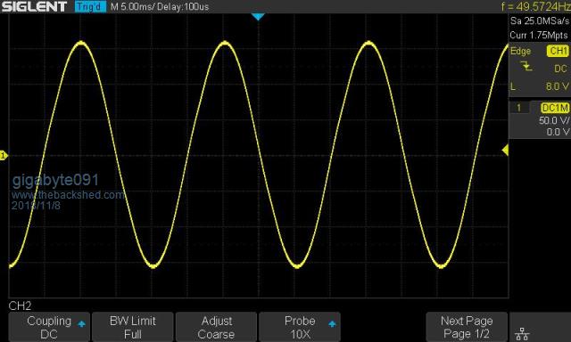 At the moment im using 330nF capacitor at transformer output, this is what i had at hand, with 5 uF there was huge backfeed into PSU, and voltmeter go over 60V and shut down everything. So now i have to tune capacitor and maybe choke... The important part is that it is working :) Program im using is 2�sinewave. Tried softstart and its working perfect, also i tried to reset MCU while inverter is running to se is there any errors but everything is alright |
||||
| poida Guru Joined: 02/02/2017 Location: AustraliaPosts: 1480 |
Gaspo: thanks for the info. I probably wont start on STM32 now. I use the Arduino IDE to drive the edit/compile/link process but as you may have seen, I don't use the libraries much, only when needed and when they don't bring problems. The Arduino Due is a ARM Cortex M3 based board and I'm familiar with the hardware (programming ADC, DAC, timer and interrupt applications directly via registers and not using the Arduino libs) but when I looked at the STM32 info, it appeared to be an alien world. I want to say again I would like to see how the code runs when you port it. wronger than a phone book full of wrong phone numbers |
||||
| poida Guru Joined: 02/02/2017 Location: AustraliaPosts: 1480 |
Good work. In the photo I see you might be using a EI type transformer. It's quite a clean sinewave. wronger than a phone book full of wrong phone numbers |
||||
| The Back Shed's forum code is written, and hosted, in Australia. | © JAQ Software 2026 |
