
|
|
Forum Index : Electronics : Various aspects of home brew inverters
| Author | Message | ||||
| johnmc Senior Member Joined: 21/01/2011 Location: AustraliaPosts: 282 |
I have use the same supplier a madness and not had one that was faulty but have managed to destroy a large amount by my own mistakes.  cheers john johnmc |
||||
| poida Guru Joined: 02/02/2017 Location: AustraliaPosts: 1432 |
The pair of IRFP2907 in TO-247 packaging arrived today. Given the SOA 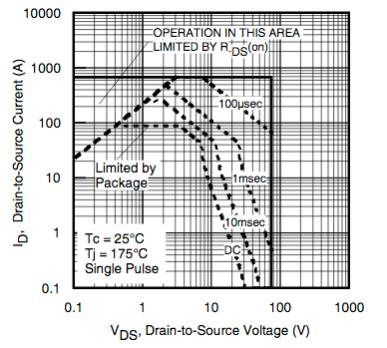 I was surprised it lasted to 3 Amps at 30V 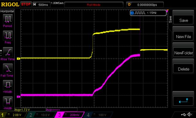 The HY4008 are still more robust in this DC test. (just when does DC become AC when we are feeding a squarewave of some duty cycle... When I read DC I think it's damn well DC. The specs say "oh, our device can handle 200 Amps. Yeah right. Oh, it's "continuous current". OK, it must be continuous for about 10 msec or less.) Anyway, just tying up loose ends. In 5 days the IRFP4110 will arrive. Probable same result. wronger than a phone book full of wrong phone numbers |
||||
| Warpspeed Guru Joined: 09/08/2007 Location: AustraliaPosts: 4406 |
Yup. When you start to look at the de-rating curve and transient thermal impedance curve that huge "200 amps dc at 25C" rated device starts to shrink down into a midget. All that many novices see at the top of the data sheet is that "200 amps maximum" and fail to realise that is just an unachievable theoretical maximum. Somewhere to anchor one end of a sloping line that could otherwise just rise to infinity at some impossibly low sub freezing temperature. Once you have defined that operating line between 25C and 160C, you can then pretty easily work out a reasonable safe operating current at any practical operating temperature somewhere in the middle. That is the purpose. Nobody expects to work at either 25C or 160C they are the absolute unattainable limits. We are only interested in the region between. You cannot run even at moderate power and hope to keep the little silicon thingy inside at 25C, even with chilled water cooling. But strangely its the 25 Celsius operating point that is used as the baseline temperature for the advertised maximum current rating. Its just the commonly accepted way of presenting the specification which is totally misleading to the uninitiated. Those skinny mosfet legs are not going to be able to carry 200 continuous amps (laugh) and the whole idea of 200 amps continuous is ridiculous for either a TO220 or TO247 package. Not only that, too many people think that the MAXIMUM rating limit line on the safe operating curve, just a whisker short of total destruction is a mighty fine place to plan on running that device. But worst of all, those counterfeit Asian parts might never even come close to what a genuine part might be capable of doing. They could be perfectly o/k or maybe not. Are you feeling lucky ? Cheers, �Tony. |
||||
| poida Guru Joined: 02/02/2017 Location: AustraliaPosts: 1432 |
All the time. Today I put one HY4008 on a PC cpu heatsink, no fan. I then put it on the high side supply to a spare inverter (Powerjack LF something) with a 10 litre hot water urn as AC load. The idea is to put about 50A DC through one HY4008. The only load of this size I have access to is an inverter powering a large AC load. I had to set up a camera to video this just in case we had some 'splosions. I precharged the inverter caps via a resistor, switched on the HY4008 with 14V gate drive from the bike battery charger and ... no sparks. I switched the inverter on and .. no sparks. I switched the urn on and .. no sparks. It ran fine for 6 minutes or more. In this case the heat generated from the MOSFET was conducted efficiently to the heatsink. I had the copper plate of the heat sink warmer than the front of the TO-247 case of the HY4408. Not a lot of heat actually, maybe 15C more than ambient with no fan. So at last I have a test that shows heat conduction to the heat sink working well. I repeat I was concerned with this but after this test today I am happy to use the heat sink temp as a guide to HY4008 junction temperature. A still from the video: 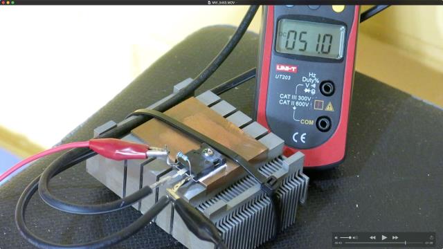 wronger than a phone book full of wrong phone numbers |
||||
| poida Guru Joined: 02/02/2017 Location: AustraliaPosts: 1432 |
And I have done this test against an IRFP4110. It is just like the others (HY4008, IRFP2907). These 3 MOSFETs do not like intermediate gate drive voltages. They want to be either fully ON or fully OFF. For completeness sake, here is the DSO capture of the 4110 failure.  I am not trying to use these MOSFETs for any novel application involving heating. I am trying to understand, in a hands-on, experimental way, how they live and die. Once one small part of the MOSFET starts conducting more than the rest of the chip, this small part gets hotter and hotter, conducting more and more and then it shorts the entire chip. If you look at the specs of some of these MOSFETs you will see the transfer curves have a temperature dependence, if the gate voltage is below something like 4V then heat induced feedback destruction will occur, if gate voltages are well above these sorts of values, there is a small negative temperature driven feedback. My thoughts on failure modes for my inverters so far are: 1 - gate drive voltages may exceed specifications, which are +/- 20V with respect to Source. I have seen voltages in excess of +20V on the gates of HY4008 under moderate load. How long can the very thin insulation layer withstand over voltage? (how long is a piece of string..) 2 - gate drive IC have specifications dictating low voltage limits with respect to ground, which is the same as the low side source pin. I have seen gate voltages well below -2 or -3 V. IR2110 specs say no gate output pin voltages less than -0.3V with respect to ground. The high limit is Vcc + 0.3 or about 12.3V How long can these drive chips put up with voltages outside these limits? 3 - putting 50A through one HY4008 does not even come close to producing enough heat to worry the MOSFET. Not by a factor of 10. Heat from Rds(on) resistance is not an issue. 4 - heat from switching ON->OFF or OFF->ON is by far the most important source of potentially damaging heat. Fast switching is a benefit. Slow switching is likely to be a source of problems of the explosive nature. This source of heat in my view accounts for the vast majority of the heat generation of the inverter. 5 - heat also is generated from the cross conduction that occurs when the high side switch goes ON, pulling it's source to V(supply) at a very fast rate of change. This causes the low side MOSFET gate to rise to voltages within the range of conduction due to the capacitive coupling of the low side MOSFET drain to the low side MOSFET's other terminals. This positive pulse, usually of the order of 4-5V will make the low side MOSFET switch ON at the same time as the high side is ON, causing cross conduction for a short interval. But the low side MOSFET is not fully ON, just in the transition region, where, as I have shown above, these MOSFETs are very weak and can not withstand much abuse. The IRFP4110 could only handle a little less than 2 Amps before destruction. Cross conduction may be the killer and I need to perform more experiments to illuminate to myself how much of a problem it is. My near term plans include fully populating one of Madness's boards and looking at how much - if any - cross conduction is visible on it. Madness has designed the gate drives to use a totem pole drive, taking it's signal from say, the IR2110 gate drive IC. This design will provide a very low impedance path for the induced voltage pulse on the low side MOSFETs and I hope to see some beneficial effect from this design. Also, to populate one of his boards requires you to drop about $70 at Jaycar for the bits and pieces, not counting the HY4008 or bulk caps... Right now I have two home built inverters, based on the Aliexpress 12 HY4008 boards. I modify them as follows: - EGS002 has the over current circuit disabled completely. I have other over current protection in place (a 100A fuse) and the faith that no matter what you ask from them, they will survive. We all need to laugh now and then... Well, I can get away with this if I only ever use a large non-saturating ferrite E core inductor. When I used the Areosharp iron core inductor, failure was only ever a week or so away. - I pull the IR2110 shutdown pin LOW and keep it there to ensure the IC always stays enabled. - The HY4008 gate drive outputs are protected with 18V Zeners to clamp high DC volts and Schottky diodes to protect against -ve DC volts. This is for the longest lived inverter. The second one I have just rebuilt after failure utilises 18V TVS devices which are more effective in >18V DC excursion clamping and provide -ve voltage clamping all in one package. I feel the need to protect the gate drive IC outputs as a matter of high priority. This also protects the MOSFET gates from exceeding +20V which is a Good Thing. These inverters seem to travel quite well under the loads I drive them here at home. So it's onward towards greater understanding of the various aspects of inverters. Oh, and here is a pic of the Arduino inverter controller I am using now. It is much more compact and probably more reliable without so many flying leads going everywhere. I run the usual 1/2 squarewave 1/2 SPWM signalling, a la EG8010. I also run my full SPWM on both 1/2 bridges type signalling, which makes for a smoother output waveform and my code has both a soft start as well as a soft stop function. This daughter board for the Arduino also allows me to run modified code which permits you to have variable output frequency (from 40Hz to 100Hz AC at full power). Additionally, I can experiment with arbitrary PWM frequencies, continuously variable from 2kHz to 70Khz. This illustrated resonance peaks of the primary choke/capacitor LC filter very nicely. Again I run this at reasonable loads such as 500W. The device only needs +12V which is referenced to DC bus ground. The trimpot allows adjustment of deadtime from about 400ns to about 2us. 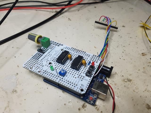 wronger than a phone book full of wrong phone numbers |
||||
renewableMark Guru Joined: 09/12/2017 Location: AustraliaPosts: 1678 |
I'm building a second one as a spare, I'll let you know when it's finished if you want to do tests on it. Just a bit time poor ATM to get it done. Reckon you'll be happy with the Mad unit, mine has been running the entire house for 2 months + now, meter shows it's made 572 kwh since being turned on. Cheers Caveman Mark Off grid eastern Melb |
||||
| noneyabussiness Guru Joined: 31/07/2017 Location: AustraliaPosts: 526 |
Poida, fantastic work as always and interesting read, again as always. . If it hasn't been supplied earlier could we please have a copy of your latest code, kinda wanna do so experimenting of my own if possible? ? If not i completely understand. ..and you use a particular chip to induce deadtime , its not in code?? I think it works !! |
||||
| nickskethisniks Guru Joined: 17/10/2017 Location: BelgiumPosts: 462 |
I like this topic! I learned a lot since the start, so turns out the hy4008 is more robust then the Irfp4110, except for the voltage. |
||||
| poida Guru Joined: 02/02/2017 Location: AustraliaPosts: 1432 |
Mark, no need for you to worry. I want to experiment with mine, first with totem pole drive, then without. All using the same DC bulk caps, same everything. So I think I need to use mine. Noneya: I attach 4 versions of the code, all running on the same hardware. This generates the familiar 50Hz squarewave on one 1/2 bridge and 20kHz SPWM on the other 2018-11-01_191506_uno_inverter_type3.ino.zip This is the variable AC output frequency (about 40 to 90Hz) version of SPWM on both 1/2 bridges. Soft start and soft stop. 2018-11-01_191526_uno_inverter_2x_sinewave_pwm_vf_output_freq.ino.zip This is outputs a fixed 50Hz output but with variable PWM from 2kHz to 100kHz approx. 2018-11-01_191549_uno_inverter_2x_sinewave_pwm_vf_pwm.ino.zip This outputs a fixed 50Hz using SPWM on both 1/2 bridges. 2018-11-01_191607_uno_inverter_2x_sinewave_pwm.ino.zip I can aid anyone with the circuitry required, etc. if you choose to have a hack of my codes. The deadtime comes with the IR2184. The pin that controls it just needs a resistor to ground. 0 ohms = 400ns, 100K Ohms = 2ms or thereabouts. Best results for me have been pretty much minimum deadtime where "best" is lowest idle input current. There is not much in it, maybe +/- 5% variance. wronger than a phone book full of wrong phone numbers |
||||
| noneyabussiness Guru Joined: 31/07/2017 Location: AustraliaPosts: 526 |
Wow... just wow... had a quick glance at your code and i think im going to take a month just to figure out whats going on 😂...good job poida, as always interesting and intriguing.. I think it works !! |
||||
| tinyt Guru Joined: 12/11/2017 Location: United StatesPosts: 441 |
Thanks poida, as always you share your work generously with no hesitation, more codes for me to learn from. Way back I attempted to modify the AS 7 version code you shared to create deadtimes in the sinewave pwm. No problem with the 50Hz ports, but I was not successful with the 20Khz ports. I even mixed assembler and C, lost more of my side hairs doing that (top is gone a long time ago). If I remember I was able to do it on the leading edges of the SPWM pulses. But I think it is impossible to do it on the trailing edges using the arduino-atmega328 hardware. Your approach of using the IR2184 to do it is best. |
||||
| poida Guru Joined: 02/02/2017 Location: AustraliaPosts: 1432 |
Tinyt: I agree, it's much easier to output one signal per 1/2 bridge and let the IR2184 take care of generating the high and low gate drives. This frees you up to try experimental stuff such as the variable AC output frequency and continuously variable SPWM. Not that there is any real benefit, only for educational reasons. wronger than a phone book full of wrong phone numbers |
||||
| gaspo Regular Member Joined: 25/06/2018 Location: AustraliaPosts: 65 |
Thanks Poida for the code. Loaded the 2x_sinewave_pwm into pro-mini and it worked right away. I was surprised how short the code is, almost fits whole on the screen. Nice soft start and stop of the sine wave. When I stop the sine wave generation (with button) there are still 20Khz varying length pulses (~100-500ns) running on the outputs. Is that intentional? 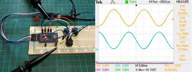 Now I need to get those IR2184. |
||||
| gigabyte091 Newbie Joined: 15/10/2018 Location: CroatiaPosts: 17 |
Great work Poida, i was also suprised to see how code is small... Here are my results: Code running, waveform after RC network (4k7 and 100n) 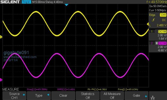 Code stopped, waveform after RC network (4k7 and 100n) 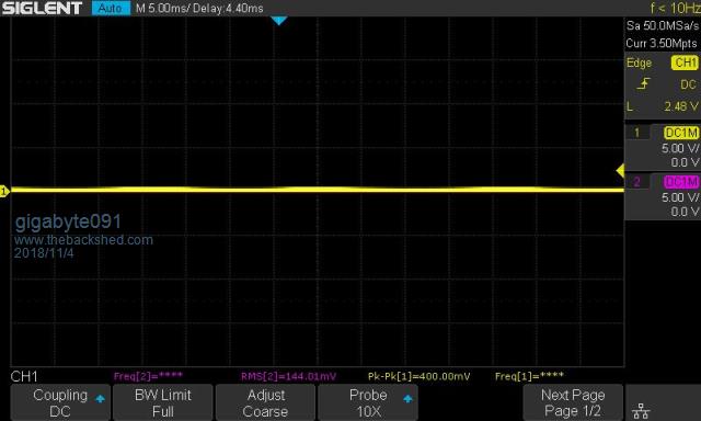 And setup:  |
||||
| poida Guru Joined: 02/02/2017 Location: AustraliaPosts: 1432 |
I'm happy to see someone run it as easily I do. The 20kHz at "stop" is intentional. If you check both output's duty cycle, you will see they are the same, at about 50%, constant no matter where you look. This output would, when fed into 2 1/2 bridges, provide the same voltage at the 1/2 bridge output. Since both outputs are the same voltage, no current will flow from one output to the other. These 2 outputs (I call them V1 and V2) are connected to the transformer primary winding. No voltage difference at V1 and V2 means no current through the transformer. I seems a bit spooky but it works beautifully (in my case anyway...) wronger than a phone book full of wrong phone numbers |
||||
| poida Guru Joined: 02/02/2017 Location: AustraliaPosts: 1432 |
Excellent to see again someone looking at this. I hope you find some fun &/or value from it. The enable output (pin 5 or PORTD, bit 5) is used to enable the IRF2184 outputs via the Shutdown input. Gate drive output enabled = logic HIGH, disabled = LOW. If you want to build something based on these codes, I want you to place a 1000R resistor on pin 5 to ground. This will pull this pin to zero volts until it is driven by the code. I found that on bootup, the Arduino lets this and other pins float with a high impedence. This may, and has in my experience, let the IRF2184 shutdown pin go high in an uncontrolled manner, at unwanted times. The Arduino outputs can easily drive the 5mA as seen due to the 1000R pulldown resistor. If you have any questions just ping me here. wronger than a phone book full of wrong phone numbers |
||||
| gigabyte091 Newbie Joined: 15/10/2018 Location: CroatiaPosts: 17 |
I have prepared my setup for EGS002 board, but i think i will go with your code for now, at least until my board arrive, but is great to have another option :) Overcurrent and temperature shutdown can be done on the hardware side, by using SD pin on drivers, or did you think about putting them in the program ? In my country i can only buy IR2184, with fixed 500 nS deadtime, but that is more then enough. |
||||
| poida Guru Joined: 02/02/2017 Location: AustraliaPosts: 1432 |
Software side is most flexible in my view. I would get a signal from current (maybe dedicated current sense amp IC), low pass it to remove noise and then you can sample it at any part of the 50Hz waveform as you like. A very low frequency filter would be equivalent to DC and give you the "average load" measure you might need. I would put the over current test in the 100Hz code that is executed in loop(). One ADC, and a few integer operations to scale, compare and set the run/stop flag to stop. There is time available to utilse the serial comms port, maybe connect a 20 x 4 LCD to it? The serial port comms code I would put outside the 100Hz part of loop(). It's just as possible to do it in hardware, op-amps are very flexible in these sorts of applications. I only ever run the IR2184 at near minimum dead time anyway so go for it. wronger than a phone book full of wrong phone numbers |
||||
Ralph2k6 Senior Member Joined: 24/09/2017 Location: AustraliaPosts: 129 |
Noob question here poida. What is to stop us from trying your Arduino method in place of the eg8010 board on something like a Madinverter. Obviously there would be board level changes required, but the Arduino code can essentially perform the same task, right? Ralph |
||||
| poida Guru Joined: 02/02/2017 Location: AustraliaPosts: 1432 |
I bought 2 boards from Madness and intend to run one via my Arduino plus IR2184 drivers board combo as seen in recently here. The other is a spare, for when my desoldering skills render the board completely munted. I want to see the difference in MOSFET gate signals between totem pole drive and gate drive IC. I will probably use the traditional code (50Hz squarewave on one 1/2 bridge & 20kHz SPWM on the other) first, then move to the 2x sinewave code. You will enjoy a lot of support from here if you build a system based on the EG8010. No board level changes are needed (on the power board) for the Arduino to work. You will need to make an interface board (taking Arduino 5V signals and driving the 2 1/2 bridges of the power board). I can help you with this if needed. wronger than a phone book full of wrong phone numbers |
||||
| The Back Shed's forum code is written, and hosted, in Australia. | © JAQ Software 2025 |
