
|
|
Forum Index : Electronics : Various aspects of home brew inverters
| Author | Message | ||||
| poida Guru Joined: 02/02/2017 Location: AustraliaPosts: 1476 |
Today I was driving to the hardware store (Bunnings, to get a spring to fix my wife's garden clippers) and passed some junk on the front grass that is waiting for local council to pickup. I saw what looked to be a generator. Took it home, blew the cobwebs out, discovered "ah, a 2 stroke". Fed it some premix and 5 pulls of the cord and it runs. 950VA 2 stroke. It powered the Makita jigsaw with ease. So now I can see how a rather poorly governed gen will go with my prototype sync code. I predict, the result will end in tears. But we must have a look anyway. How two AC sources will behave when connected in parallel is something I have no idea about. I figure that the inverter, which with luck will be in sync with the gen, will sense it's AC output voltage and PWM up or down to maintain output compared to set point. At times the gen will be doing enough to meet or exceed nano1's setpoint. So, gen is running, with X AC volts. Inverter is running, with Y AC volts initially and ramps up or down PWM to make the now shared AC output = set point when you close the contact breaker. (not me...) Some load is on, no change, the gen can handle the output. Some more load is on, taking gen AC down, past inverter setpoint and so PWM is increased and AC voltage maintained. Heaps of load is on now, inverter is maxed nearly, not to extent of exceding DC current limit, and gen is doing it's bit. Meanwhile, the AC frequency has been bouncing around and about like a loon... Do you think this will work? Later I will get some DSO captures of the generator output at idle and under some load. I will be most interested to see a graph of nano1 data as it attempts to maintain sync. The graph will show the nano1 AC output frequency trim factor, a proxy for output AC frequency, and this will be up and down very much. The graph will also show phase difference. This is getting interesting. wronger than a phone book full of wrong phone numbers |
||||
| Tinker Guru Joined: 07/11/2007 Location: AustraliaPosts: 1904 |
I suspect you are in for a bit of fun poida, wish I was there to watch  . .How to synchronize two AC sources was taught to me many many years ago, using a rotary AC generator driven by an electric motor as power source. This was synched to 50Hz mains frequency. The usual filament bulb arrangement between the two (I think it was 3 phase) showed when the phases & speed matched. The bulbs would light and darken slower and slower as the speed started to match the 50Hz, then when the bulbs were dark we would hit the switch to connect both sources together. If that switch was thrown too soon or too late the generator would give a mighty GROAN and all the fuses blew. Note to self: connect fuses when testing. The generator was now locked to mains frequency. It continued to run at the speed (dictated by the number of poles) even if the motor power was reduced. If driving power was increased, power was pushed into the mains - still at the same rotation speed. This was like a fly making an elephants tail to twitch in sync. If done the other way round that might cause problems with frequency stability. Its also a bit of an unknown with an inverter power source - these things did not exist back then  -, and, some of the petrol/ diesel generators have inverters built in -, and, some of the petrol/ diesel generators have inverters built in  . .My gut feeling tells me that if a grid tie inverter *can* push power into our inverters then rotating machinery should also do so. A grid tie inverter does lots of checking (mine takes 60 seconds) before it throws the relay to pair up. If the grid tie input drops below a factory set point it will disconnect. What we need to do is to duplicate that disconnect somehow by sensing when the feedback frequency from the 12v transformer/ opto no longer can be matched. As in dropping speed to stop. As I said above, with an ordinary AC generator, once synced it keeps running at the inverter frequency, even driven by it if input power is lacking. No problem if the input power is an electric motor but a big problem if its a piston engine. I know little about the innards of an inverter type petrol/ diesel generator so no guesses what happens with these. You are the code expert, can you put limits on that AC feedback info, outside which the sync relay cuts out? Perhaps you can simulate this with your sine wave generator's output driving a suitable small transformer before you fire up your genny find. I am making a mini inverter (~500W) for my experiments with that synching. This should make less magic smoke if things go wrong. I'm not at all keen to do any synching to my big inverters until any bugs are banished for good.Unfortunately it won't be finished until March as I will be away for a while. Klaus |
||||
| tinyt Guru Joined: 12/11/2017 Location: United StatesPosts: 559 |
Here is rev B Gerbers, plus schematic, BOM, and notes. 2018-12-11_061353_Nanoverter_B_Gerbers_Others.zip A gerber viewer can be downloaded here (gerbv) Please do final review and if OK, feel free to do the next step. I hope I did not make any mistakes. |
||||
mackoffgrid Guru Joined: 13/03/2017 Location: AustraliaPosts: 460 |
Hi TinyT. Did you do those drawings in Kicad? I've been following this topic with interest but not to component level. Had a basic look at you gerber files and they look fine, but as I said I'm not that close to the nity grity. Poida, I watch with great interest how you go with syncing with a crappy 2 stroke genie , good onya :-) |
||||
| tinyt Guru Joined: 12/11/2017 Location: United StatesPosts: 559 |
I used the old orcad pcb layout 16.2 (the last release) and the bundled specctra autorouter. |
||||
renewableMark Guru Joined: 09/12/2017 Location: AustraliaPosts: 1679 |
No more additions/alters? I see in the notes holes are plated through, but I can't see an option on the order form. Can someone check this over for me please?  Cheers Caveman Mark Off grid eastern Melb |
||||
| renewableMark Guru Joined: 09/12/2017 Location: AustraliaPosts: 1679 |
With the DIP chips is it ok to use SMD on a board like this the same way the 8010 is mounted, as they are more readily available and a fair bit cheaper. Cheers Caveman Mark Off grid eastern Melb |
||||
| tinyt Guru Joined: 12/11/2017 Location: United StatesPosts: 559 |
Non-plated thru holes require additional procedure and maybe cost a little bit more. Most PCB fab houses assume that holes are plated thru and you have to specify or have another drill file for non-plated thru holes. What I did is just clarified in the note the hole type. |
||||
| tinyt Guru Joined: 12/11/2017 Location: United StatesPosts: 559 |
May or may not work because of the PCB adapter size (17.7mm x 17.7mm). The adapter will have overhangs that might interfere with components that are soldered close to the DIP socket. |
||||
| renewableMark Guru Joined: 09/12/2017 Location: AustraliaPosts: 1679 |
That wont work actually as the footprints will be totally different. Cheers Caveman Mark Off grid eastern Melb |
||||
| tinyt Guru Joined: 12/11/2017 Location: United StatesPosts: 559 |
You are correct, I did not see the dimensioned drawing. Row spacing is too large. |
||||
| poida Guru Joined: 02/02/2017 Location: AustraliaPosts: 1476 |
Part 25: generator waveforms (from the cheap Chinese 2 stroke genny) I found this on the side of the road and thought it a good teardown candidate. (but mine is very rusty, corroded and filthy, not like the photo)  But it ran, sort of OK, and made power. It has a rather bad AC waveform and seems setup for 60Hz. Oh well. White is my street power waveform. Blue is the generator's waveform (60 Hz approx.) 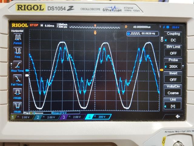 I do not want to have to make the nanoverter sync to this rubbish. Surely more reasonably priced and specified generators produce a decent output waveform. It got me thinking if we really need AC sync at all. In some cases where you just want extra power you could have the generator output rectified and fed into the battery. No AC sync is needed now. We already have a very efficient mains AC to DC conversion system available in the form of a large toroid, wired for 240V AC to 60V AC output. Rectification of high currents can be done with a MOSFET active full bridge rectifier, or other options. Maybe use the LT4320 ideal diode bridge controller. Have that drive some HY4008 MOSFETS and feed that into a charge controller of some sort. Or just stop the generator when it's enough. 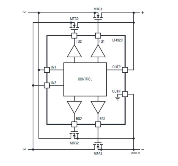 wronger than a phone book full of wrong phone numbers |
||||
| Tinker Guru Joined: 07/11/2007 Location: AustraliaPosts: 1904 |
Agree with you there poida, that generator output looks rubbish. Unlikely its the output of a 240V rated alternator. I guess some lower voltage boosted by cruel electronic means. Rotary AC generation produces a very good sine wave when left un adulterated. The frequency is governed by rotational speed. If this was my 'find' I'd take it apart and see how exactly that AC is generated. But, I still would be interested in syncing two AC wave forms. In my case this being two inverters with one (smaller one) powering the lights and the other the power outlets. Both are on separate wiring runs in my house. As your program is now, could it do that? I won't be able to test it for a while but please keep a copy of your code for me to download when I get back home in March. Klaus |
||||
| renewableMark Guru Joined: 09/12/2017 Location: AustraliaPosts: 1679 |
It would be a shame if you gave up on the sync function, that really would be a great feature. I think most people would be using much better gens than that if they were serious about charging a big battery bank, (my one is a 3000w pure sine inverter type). If you stipulated that it was only meant for use with other pure sine power then you have covered yourself. After all how could you possibly sync a non sine to a sine output. Anyway up to you. Cheers Caveman Mark Off grid eastern Melb |
||||
| mackoffgrid Guru Joined: 13/03/2017 Location: AustraliaPosts: 460 |
That waveform probably indicates why it was left on the side of the road. I have a Chinese "8kW" :-) genie and while I think the output wasn't pretty I'm pretty sure it didn't look like that :-) Its a 3hr drive away so I can't have a quick look. I do say this with a grin on my face but I still hope you have a go at syncing with little bugger. As with many others on this forum, you're doing bloody good work. Cheers Andrew |
||||
| renewableMark Guru Joined: 09/12/2017 Location: AustraliaPosts: 1679 |
Hi Poida, have you made a decision on the sync function? If you have made it to sync with mains, then it should sync with a pure sine generator, you can borrow my gen if that helps. Cheers Caveman Mark Off grid eastern Melb |
||||
| renewableMark Guru Joined: 09/12/2017 Location: AustraliaPosts: 1679 |
Another good reason to implement the sync would be to run two inverters. Each inverter could have it's own solar array and battery. You could then have the option to use flooded LA batteries on one system and possibly lithium or gel on the other, which would be difficult to combine as a dc feed power for one inverter. This way each one could be independent in their dc power supplies, but feed the mini grid with the same AC power. Also giving you added protection from just a single power supply failure. Cheers Caveman Mark Off grid eastern Melb |
||||
| poida Guru Joined: 02/02/2017 Location: AustraliaPosts: 1476 |
I've improved the sync code's performance. The PID closed loop tracking (of the mains) needed finer control over the output frequency. Also I have a hacked fix for the spurious firing of the interrupt from the mains ->optocoupler->D2 pin signal path. This better code will be incorporated into the nano1 code. How the sync code works is (right now, with much improved tracking) is: once every 50 Hz, check the phase difference between mains and inverter. Feedback this difference into the output frequency of the inverter. Limit the feedback to a small but quite functional range (to keep the inverter from blowing up) but still be able to obtain sync from mains freqs of 50 +/- 3Hz Only ever let the interrupt code run once per 50Hz cycle. Added: check if in sync, if so, discard any interrupts that are earlier or later than about 0.5ms compared to when it should occur. If not in sync, permit these interrupts, since they are needed to obtain sync. Use a 1 in 1024 fractional divider for the output frequency clock, previously this was 1 in 256. Smoother tracking now. wronger than a phone book full of wrong phone numbers |
||||
| renewableMark Guru Joined: 09/12/2017 Location: AustraliaPosts: 1679 |
Good work mate, we all appreciate your efforts. Bits have started to arrive, I'll order the boards tomorrow. Cheers Caveman Mark Off grid eastern Melb |
||||
| poida Guru Joined: 02/02/2017 Location: AustraliaPosts: 1476 |
Here is the sync performance during connection of AC sync source. I have a deliberately poor connection, to try and force some bad behaviour of the code. Yellow is AC source Blue is inverter AC output Light Blue is short 7.5us pulse from sync interrupt code execution. Each pulse indicates the sync code has run, trying to find sync with external signal. Once the signal is applied, it takes some time to get synchronised. Pink is 50Hz beat from inverter, used for DSO trigger sync, forget about this one. First we see a close-up of a poor application of external sync. Notice how much on and off sync input signal there is due to me pushing a wire into a breadboard terminal. The external AC is about 90 degrees later than the inverter. 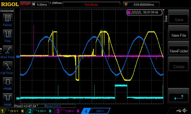 Next is a view of sync capture, taking about 10 50Hz cycles or 0.2 of a second, to achieve sync. 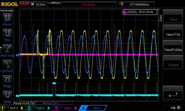 The wide pulse is due to the sync interrupt being triggered at the wrong time and so my code just exits early, leaving the output high until the next time. This is by design. I only want the sync code to run once each 50 Hz cycle. My street power has the top and bottom clipped a bit, for some reason. I don't know why and I think I just need to accept that an external AC sync source will have unexpected shapes. wronger than a phone book full of wrong phone numbers |
||||
| The Back Shed's forum code is written, and hosted, in Australia. | © JAQ Software 2026 |
