
|
|
Forum Index : Microcontroller and PC projects : PicoMite V5.07.00b0 - beta firmware
| Author | Message | ||||
| Mixtel90 Guru Joined: 05/10/2019 Location: United KingdomPosts: 8910 |
Cheers, Tom. :) @matherp "OPTION AUTORUN now allows a number between 1 and 10 or OFF" Fairy nuff, but other platforms use OPTION AUTORUN ON|OFF. I (apparently wrongly) assumed that ON was still one of the options. :) Edited 2021-07-23 23:12 by Mixtel90 Mick Zilog Inside! nascom.info for Nascom & Gemini Preliminary MMBasic docs & my PCB designs |
||||
| matherp Guru Joined: 11/12/2012 Location: United KingdomPosts: 11500 |
For the manual GP20 can also be used for SPI0RX SPInCSN pins are not relevant to the PicoMite and should be omitted from the diagram SETPIN b,SPInTR should be SETPIN b,SPInTX BITBANG/BITBANG HUMID is a command not a function PIO INIT MACHINE appears twice OPTION AUTORUN n specifies which flash slot to run on power-up or reset MATH M_INVERSE command and MATH(DETERMINANT function are not currently in any other port: all other MATH stuff is exactly as per CMM2 READ command can now take arrays e.g. a() and will read to fill the array. For multi-dimensional arrays the leftmost index is the fastest moving BLIT LOAD [#]n, "filename" [,xstart] [,ystart] [,xlen] [,ylen] This loads into blit buffer n the image from filename. The image must be a 24-bit bmp. The optional parameters specify the start position in the image to load from and the width and height to load. Also, the manual should reference your PIO compiler. This is very important code and subject to your agreement should be distributed with the PicoMite firmware when officially launched Edited 2021-07-23 23:11 by matherp |
||||
| vegipete Guru Joined: 29/01/2013 Location: CanadaPosts: 1180 |
Maybe in this particular instance, "ON" should have the value "1"? Then code ported from other 'mites needs less rework, although it must be saved in slot 1. Visit Vegipete's *Mite Library for cool programs. |
||||
| Volhout Guru Joined: 05/03/2018 Location: NetherlandsPosts: 5931 |
First test with ADC command. I looked at Peters example code, and have created this program ' test ADC burst read ' connect ADC input to PWM output using RC filter to create triangle-ish wave ' PWM = 50Hz ' ADC takes 1024 samples, running at 50kHz pwm_freq=50 samples=MM.HRes-1' 1023 adc_freq=pwm_freq*samples gain=MM.VRes/3.3 'reserve memory Dim array!(samples) 'open PWM(GP18) and ADC(GP26) SetPin GP18,pwm1A SetPin GP26,ain ADC open adc_freq, 1, ready_int 'start PWM PWM 1,pwm_freq,50 ' 50% = square wave Pause 100 'start ADC ADC start array!() Do :Loop End Sub ready_int ADC close CLS For i=0 To samples-1 'Print Str$(array!(i),2,2), Line i,gain*array!(i),i+1,gain*array!(i+1),1,RGB(yellow) Next i Print "ready" End End Sub When I run this program it draws a square wave (with rounded edges if an RC filter is added, otherwise a nice square wave) on the LCD screen. However, if I run the program several times after eachother, I get at PANIC error message. Not sure why, I do a ADC close in the interrupt, and an END (should close down the DMA's. 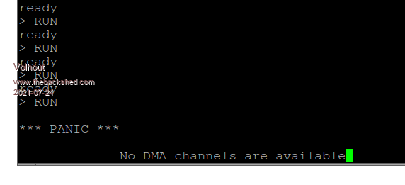 PicomiteVGA PETSCII ROBOTS |
||||
| matherp Guru Joined: 11/12/2012 Location: United KingdomPosts: 11500 |
Thanks for the report - will fix in next beta |
||||
| led-bloon Senior Member Joined: 21/12/2014 Location: AustraliaPosts: 209 |
@Mixtel90 For the manual 00b1.rtf Great job, thanks led Miss you George |
||||
palcal Guru Joined: 12/10/2011 Location: AustraliaPosts: 2039 |
On the PiPico pinout why are there multiple SPI0 and SPI1 RX and TX pins. Which ones do I use to wire up an ILI9341 display. "It is better to be ignorant and ask a stupid question than to be plain Stupid and not ask at all" |
||||
TassyJim Guru Joined: 07/08/2011 Location: AustraliaPosts: 6538 |
It is up to you. The pico allows you to move the various functions around so you can 'fit' different board layouts. They just have to be compatible pins. Pin allowable functions are in the datasheet. I have kept mine simple. All the fixed connections are grouped together on pins 10 to 20 to fit my veroboard layout. So my configuration requires: OPTION SYSTEM SPI 14,15,16 OPTION SDCARD 17 OPTION LCDPANEL ILI9341,L,10,11,12 OPTION TOUCH 19,20 GUI CALIBRATE 0, 250, 504, 925, 747 Jim VK7JH MMedit |
||||
| palcal Guru Joined: 12/10/2011 Location: AustraliaPosts: 2039 |
OK got it. I'm designing a PCB to take the place of the 170 Backpack. I made one that used the E28 but now I want to use the PicoMite. "It is better to be ignorant and ask a stupid question than to be plain Stupid and not ask at all" |
||||
| Mixtel90 Guru Joined: 05/10/2019 Location: United KingdomPosts: 8910 |
Beat you to it, palcal. ;) "LCD+Pico combo" thread. I trust that your design will be double sided from the word go though. Mine was originally a DIY design. Edited 2021-07-24 17:46 by Mixtel90 Mick Zilog Inside! nascom.info for Nascom & Gemini Preliminary MMBasic docs & my PCB designs |
||||
| palcal Guru Joined: 12/10/2011 Location: AustraliaPosts: 2039 |
Yes double sided, I use DipTrace and get them made by PCB GoGo. "It is better to be ignorant and ask a stupid question than to be plain Stupid and not ask at all" |
||||
| jaybek Newbie Joined: 25/05/2020 Location: GreenlandPosts: 18 |
I presume this 3.2" display will work too, as it's got all the same specs as the 2.8" ILI9341, except it's bigger. https://www.aliexpress.com/item/33040270372.html Has anyone tried it? #MeTo ZX81 |
||||
| Mixtel90 Guru Joined: 05/10/2019 Location: United KingdomPosts: 8910 |
I think it would work fine on mine, but the fixing holes don't line up. I assume the same will apply to palcal's board unless he designs it round the 3.2" display. Mine was very much designed round what I happen to have, and the fact that it will fit in a standard plastic box which I'd already cut out for the original backpack assembly - I'd no intention of buying another display. It almost broke my heart having to buy another RTC module because my existing one is far too bulky. lol Mick Zilog Inside! nascom.info for Nascom & Gemini Preliminary MMBasic docs & my PCB designs |
||||
| Mixtel90 Guru Joined: 05/10/2019 Location: United KingdomPosts: 8910 |
Update to the doc for the PicoMite. I think I've caught all the comments so far, plus made a couple of other slight changes. PicoMite Beta docs 00b6.zip . . Mick Zilog Inside! nascom.info for Nascom & Gemini Preliminary MMBasic docs & my PCB designs |
||||
Cyber Senior Member Joined: 13/01/2019 Location: UkrainePosts: 161 |
I would like to know too... |
||||
| Mixtel90 Guru Joined: 05/10/2019 Location: United KingdomPosts: 8910 |
This is how I understand it, Cyber: We can have 128 commands and 128 functions. Currently LIST COMMANDS is showing 129 (I'm not sure why - I suspect that UPDATE FIRMWARE may not count as it can't appear in a program). Those restrictions were decided when MMBasic was written, are fundamental to how it works, and can't be changed without major work. They weren't restrictions at the time, but quite a bit has been added since. So, at the moment, a separate SERVO command can't be added because there's simply no room for it in the command table - another command would have to be dropped to make room for it. The very best that could probably be done (if there's space) might be BITBANG SERVO, but there really isn't a need for it as servos can be handled using PWM in MMBasic. You can always write SUB SERVO(servo_number, angle) ... END SUB if you want something that reads nicely in a program. It just needs a little thought to sort out how to handle the sevo number / PWM channel association. Select Case springs to mind. You can have 8 servos, one for each PWM channel. You could make <angle> a percentage, 0-180 or -90 to +90 depending on what you want. The restrictions are on "root" commands so what matherp has done in some cases is to "multiplex" commands so that they can do various functions. So, for example, MATH only takes up one slot in the table but gives 26(?) commands on the PicoMite. Changing HUMID to BITBANG HUMID freed up another slot. EDIT: You can have up to 16 servos - I forgot about the A-B bit. lol Edited 2021-07-25 18:36 by Mixtel90 Mick Zilog Inside! nascom.info for Nascom & Gemini Preliminary MMBasic docs & my PCB designs |
||||
| Mixtel90 Guru Joined: 05/10/2019 Location: United KingdomPosts: 8910 |
@matherp Hardware question... Do DOUT pins have a pullup resistor switched on? I've seen 50uA or so of leakage from pins where the program has been terminated with ctrl-C rather than the pins either set to zero or Setpin off. (i.e. a "dirty" shutdown). In both those cases the output disappears as expected. I've not tested this using an led from 3v3 via a resistor. Mick Zilog Inside! nascom.info for Nascom & Gemini Preliminary MMBasic docs & my PCB designs |
||||
| lizby Guru Joined: 17/05/2016 Location: United StatesPosts: 3783 |
PicoMite PCB with 2x20 expansion PCB + modules  This is the same 2x20 board as shown previously for the F4 and CMM2, with a few wired modifications to fit the PicoMite PCB (mainly caused by fewer ADCs than on the F4 and CMM2, and some issues with PWM, and a desire not to take up 6-8 pins for an SPI LCD). Here's the pin usage:  I used all of the Picomite pins, but had to reuse two of them to provide signals to all pins of the 2x20 connector. It was probably not a wise choice for flexibility, but I used pico pin 34 for both connector pins 12 and 13, and pin 11 for connector pins 15 and 16. I wanted to retain a display for the module/device options, and use the rotary encoder to make choices. I used a 128x64 I2C SSD1306, with the option names reduced to 6 characters for the first column of 5, 5 characters for the second, and 6 for the third. > option list OPTION SYSTEM I2C GP10,GP11 OPTION LCDPANEL SSD1306I2C, LANDSCAPE OPTION RTC AUTO ENABLED OPTION GUI CONTROLS 59 OPTION MEMORY 60160, 100608 The second biggest change in the code was to "atomize" the performance of the module, to make it more like a state machine handling multiple modules simultaneously. I used SETTICK to extablish a 100ms minor tick, and 500ms for a major tick. The LEDs flash every 500ms, and the servo and PWMing changes occur every 100ms. Here's what the menu looks like. Turning the rotary encoder causes the focus to change. The in-focus menu item will flash. If it has been selected by clicking the rotary encoder button, it will flash highlighted--black on white; if not selected, white on black.  Pic with MCP23017 flashing lights, 3-color LED cycling through 8 states, red LED blinking on and off, and LED attached to the SPI1 port blinking:  Here's a youtube video which shows: 1) menu selection by rotary encoder shown on SSD1306 I2C LCD 2) 3-color LED 3) LED flashing 4) Buzzer 5) MCP23017 flashing 16 LEDs 6) Servo slewing from full clockwise to full counter-clockwise and back 7) PWMing of 5V LED using MOSFET module 8) Dimming/brightening of 5V LED using MOSFET module using potentiometer 9) ultrasonic distance measuring module using COM0 10) flashing of LEDs attached to SPI1 MISO, MOSI, CLK, and CS Picomite on Youtube Code: sensors.zip Picomite PCB gerbers: picomite_mcp2.4_2021-07-25.zip 2x20 Expansion PCB gerbers: 2x20_breakout_V3_2021-07-25.zip EagleCad files: Picomite PCBs.zip PicoMite on FruitOfTheShed PicoMite, Armmite F4, SensorKits, MMBasic Hardware, Games, etc. on FOTS |
||||
| palcal Guru Joined: 12/10/2011 Location: AustraliaPosts: 2039 |
My humble Backpack offering, still needs a lot of checking. 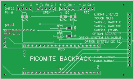 "It is better to be ignorant and ask a stupid question than to be plain Stupid and not ask at all" |
||||
| led-bloon Senior Member Joined: 21/12/2014 Location: AustraliaPosts: 209 |
I don't wish to offend ANYONE but... This thread is for PicoMite beta firmware. There are some great people making some great PCBs for the PicoMite, but I believe they should all be in a "new" and different thread, I don't know, maybe called "PicoMite Hardware"? Panky & zeitfest created their own threads, and good on them! No offence but, can we keep threads on topic? Just a thought led Miss you George |
||||
| The Back Shed's forum code is written, and hosted, in Australia. | © JAQ Software 2026 |
