Notice. New forum software under development. It's going to miss a few functions and look a bit ugly for a while, but I'm working on it full time now as the old forum was too unstable. Couple days, all good. If you notice any issues, please contact me.
tinyt Guru Joined: 12/11/2017 Location: United StatesPosts: 431
Posted: 02:54am 29 Jun 2018
Copy link to clipboard
Print this post
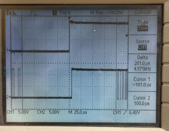
Then it will look like this.
The picture is a screen capture of moving 'bar code' because of continuous triggering. Too bad I cannot upload video clip. Still it shows absence of pulses 100usec pre/post trigger. If the TDS 220 still misses pulses in that area, I think it is time for me to junk it. I also believe that this contributes to the distortion near zero crossing. Because of the jittering 'bar code' I think I agree with poida that this asic uses code instead of programmable logic.
Also, I think I have left the impression that I am not going to use a choke. ESL problem I guess.
Warpspeed Guru Joined: 09/08/2007 Location: AustraliaPosts: 4406
Posted: 03:22am 29 Jun 2018
Copy link to clipboard
Print this post
I would not bother too much about trying to see the actual PWM cycle by cycle.
What is much more important is what it represents. And you can get a pretty good look at that with the resistor capacitor filter circuit that Mad posted earlier in the thread.
If that looks o/k, then the PWM that produced it must be o/k too.Cheers, �Tony.
poida Guru Joined: 02/02/2017 Location: AustraliaPosts: 1392
Posted: 12:02pm 02 Jul 2018
Copy link to clipboard
Print this post
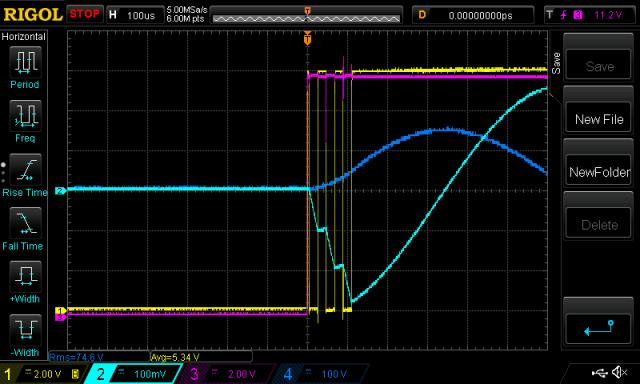
I can confirm this. I apply 12V to the board, which brings up the 5V supply quite soon afterwards and then this: Yellow 24Khz pwm gate drive Pink 50Hz gate drive Light Blue primary current (10 A RMS/div) Dark Blue, AC output on secondary.
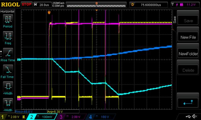
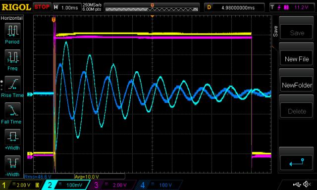
zoomed in, 20 usec/div and back a bit, showing the ringing of the toriod/inductor/capacitor combo that results from this huge pulse of energy. The ringing is an audible click too. Every time I apply power I get the click. It seems to be about 825Hz. hmmm But I get a lovely smooth AC output waveform from this, so I'm happy.
This also shows the inductor behaviour very clearly, you can see the current rise/fall linearly during each switch event (i.e. V1 to battery, V2 to ground), and then current drops slowly when the switch is open (i.e. connecting the primary winding ( V1 ) to ground and V2 to ground). wronger than a phone book full of wrong phone numbers
Madness Guru Joined: 08/10/2011 Location: AustraliaPosts: 2498
Posted: 12:35pm 02 Jul 2018
Copy link to clipboard
Print this post
I have seen the SPWM side of the EG8010 putting out square wave for some time when feeding a DC voltage into the VFB to fool the control board to keep running. Seems to be there to kick start the toroid or something, if the VFB is quite low it keeps the square wave running longer.There are only 10 types of people in the world: those who understand binary, and those who don't.
tinyt Guru Joined: 12/11/2017 Location: United StatesPosts: 431
Posted: 03:30pm 02 Jul 2018
Copy link to clipboard
Print this post
Thanks poida for confirming. If there is a huge pulse of energy created by the switching of the mosfets at this time, maybe it is over stressing the mosfets leading to their eventual failure, just guessing. And even if it does not (30A peak is shown), maybe this condition should be addressed.Edited by tinyt 2018-07-04
poida Guru Joined: 02/02/2017 Location: AustraliaPosts: 1392
Posted: 10:01pm 02 Jul 2018
Copy link to clipboard
Print this post
Tinyt: I think this is taking us to the question:
When do these inverters of ours fail? a/ upon switch on b/ during soft start c/ soon after soft start complete e/ 5 minutes into run f/ 5 months into run
Oztules will have you understand the robust characteristic of the HY4008 when driven properly. I think all problems come from over voltage on the gate or poor timing of gate drive. Over current never seems to me to be the initiating cause of destruction, rather the clearly spectacular results of something that triggered failure of the mosfet function.wronger than a phone book full of wrong phone numbers
Warpspeed Guru Joined: 09/08/2007 Location: AustraliaPosts: 4406
Posted: 12:53am 03 Jul 2018
Copy link to clipboard
Print this post
Does this popping drama happen every single turn on, or does it only happen sometimes?Cheers, �Tony.
wiseguy Guru Joined: 21/06/2018 Location: AustraliaPosts: 1017
Posted: 01:21am 03 Jul 2018
Copy link to clipboard
Print this post
Lets add a couple more to Poidas question g/ during an over-current event h/ restarting after an over-current event i/ during a major change in load <than or >than
Some other ways FETs can fail also include shoot through (unintended gate drive/turn on) Avalanche failure due to incorrectly clamped inductive loads Insufficient gate drive Instability (parasitic oscillations) from paralleling Mosfets without due mitigation. Exceeding the Fets or body diode current/energy rating Mechanical failure internally - usually cause by over-current events that stress bonds etc but dont initially cause functional failure.
There may be others too Edited by wiseguy 2018-07-04If at first you dont succeed, I suggest you avoid sky diving.... Cheers Mike
Warpspeed Guru Joined: 09/08/2007 Location: AustraliaPosts: 4406
Posted: 01:44am 03 Jul 2018
Copy link to clipboard
Print this post
j/ Non simultaneous turn on, or turn off of multiple parallel mosfets, where the first to turn on, and the last to turn off can cop most of the switching load. Getting four to work in a bridge is a lot easier than getting a dozen or more to all load share together during very rapid switching.
k/ Noise induced into long and poorly placed gate driver leads from large adjacent heatsinks that have very high dv/dt, and from shortcomings in grounding between the power board and driver board.
l/ Uncertain power supply sequencing during power up and power down. Just because it goes bang when you power it up may not actually be the problem. Parts can fail due to problems during shutdown. It only goes bang when you later try to switch it back on because of previously damaged parts.Cheers, �Tony.
Madness Guru Joined: 08/10/2011 Location: AustraliaPosts: 2498
Posted: 02:18am 03 Jul 2018
Copy link to clipboard
Print this post
I have had no unexplained failures after adding totem pole gate drive to the bigger inverters with 24 MOSFETs.There are only 10 types of people in the world: those who understand binary, and those who don't.
Tinker Guru Joined: 07/11/2007 Location: AustraliaPosts: 1904
Posted: 10:04am 03 Jul 2018
Copy link to clipboard
Print this post
Thinking back, most of my 'big bang' events happened at switch on.
Had 'bangs' with the IRF TO220 mosfets we used initially. Had 'bangs' with very expensive 4 terminal 200A mosfets. Had 'bangs' with the HY4008 mosfets.
Different board layout and totem pole drivers stopped all that. Plus, of course , learning the hard way how to start the thing up correctly.
I can only remember one over current 'bang' and that happened with a smallish toroid and experimental driver board. Klaus
Madness Guru Joined: 08/10/2011 Location: AustraliaPosts: 2498
Posted: 10:36am 03 Jul 2018
Copy link to clipboard
Print this post
What do you mean by starting up correctly Klaus? I can start with everything turned on and it is happy, the soft start just ramps up to 5KW or so load that then tapers off as the fridges, pump etc get going. Never had an overload failure, I was trying to start a 5KW AC compressor once that stalled and that happened is it popped the 20A breaker. Soft-starting with the breakers turned on I think is safer than starting the inverter and turning on the main switch to your house.
What the Inverter did not like was when my GTI failed due to a short to ground in the experimental regulator I was using, that killed the MOSFETs.There are only 10 types of people in the world: those who understand binary, and those who don't.
Tinker Guru Joined: 07/11/2007 Location: AustraliaPosts: 1904
Posted: 02:45pm 03 Jul 2018
Copy link to clipboard
Print this post
As you know I use a bypass resistor (33R) across one of the DC battery connection breakers. This was with my inverter (early version) still in parts on a test assembly, not as it is now with the totem pole drivers etc.. Now, being impatient and not waiting long enough for the big caps to charge fully before applying full DC did let out the smoke. Not having that on/off switch properly rigged might have been another case, it was a while ago. A big learning curve was having been had...
I did use those big clamps, like on jumper leads, to connect to the battery and I'm sure there were occasions when I disconnected & reconnected with these without turning the off switch (pin6) first. This switch is now always first & last operated when doing anything with the battery cables.
I now wish I had done a diary with every malfunction detailed, it might have helped others. As it was, being embarrassed by the 'bangs' I re arranged a lot of things at once, made new PCB's, tried different chokes and tried just about everything I had read on this forum.
Success only came with my present arrangement of the PCB's & layout and the parts. I think it does play a role just how things are connected together, rather than long haphazard connections.
The other thing I learned is not to fit everything into a tight enclosure and then have the mosfets blow on first switch on. Takes ages to get it all apart and replace the damaged bits.
Hence my construction into an open frame that holds everything in its assigned final place but allows full access. The 'case' is then screwed on around it after all tests were successful.
As my inverter works now, if the battery is disconnected the under voltage sense would trip the SCR (the thing is then still running for a while on capacitor power) and safely shut the EG8010 down. Ditto if the battery is re connected. As the capacitors charge slowly up the EG8010 gets its 5V but is prevented from soft starting (by the 10K on pin 6). At the same time the under voltage remains being tripped as this requires at least 50.5V at the capacitors. The 5V comes on first to power the chip but two things stop it from trying to start an output. So, even leaving the ON switch on would not automatically re start it after battery power comes back.
To get it going again, after the green 'ready' LED shows full capacitors, I first switch the On switch and then push the reset to disable the under voltage trip situation. It will then soft start under load. I prefer it this way, physical turn on rather than automatic.
Works for me. Klaus
Madness Guru Joined: 08/10/2011 Location: AustraliaPosts: 2498
Posted: 08:23pm 03 Jul 2018
Copy link to clipboard
Print this post
I have a 80A DC breaker as the main power switch, it just gets turned on, no resistor to gradually charge the capacitors. Just turn on the breaker and turn on the switch to pin 6 away it goes, this has never failed. Not planning to try it but it probably would be fine if pin 6 was turned on when the breaker is turned on.
One tip for everybody is if you are using a GTI and it is back charging turn the GTI off before shutting down your inverter. If not the GTI somehow keeps running for a 500ms and you can hear the toroid reacting to it. This has resulted in releasing the smoke when the Inverter was powered on again.There are only 10 types of people in the world: those who understand binary, and those who don't.
Tinker Guru Joined: 07/11/2007 Location: AustraliaPosts: 1904
Posted: 09:03am 04 Jul 2018
Copy link to clipboard
Print this post
Thanks Gary, I think for me its a case of once burned twice...
Good tip, I did not think of that but it makes obvious sense. I will include that in the shut down notice I had planned to place near the inverter/ batteries.Klaus
tinyt Guru Joined: 12/11/2017 Location: United StatesPosts: 431
Posted: 04:54pm 05 Jul 2018
Copy link to clipboard
Print this post
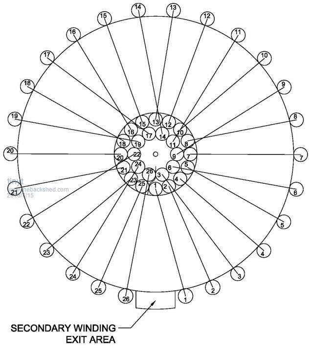
A sketch of my impossible primary winding approach (the inside is similar to a motor stator). The two colors is just to visually differentiate adjacent turns. The 355.8 mm turn length is estimate of maximum possible for a wire strand. Still making my fixtures, tools, etc. (plus doing a lot of prayers).
Edited by tinyt 2018-07-07
tinyt Guru Joined: 12/11/2017 Location: United StatesPosts: 431
Posted: 04:17pm 14 Jul 2018
Copy link to clipboard
Print this post
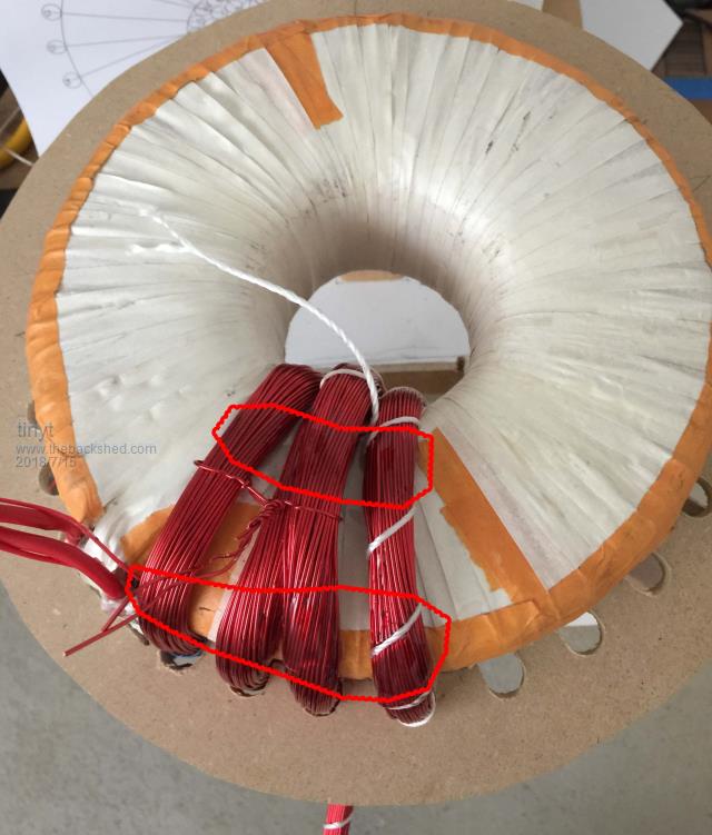
That wedge shaped strand bundle is just an impossible dream.
Plan B:
Winding two at a time and applying 5 minute epoxy at the areas shown to keep the winding in place.
The plan is after all turns are done, cut and remove the strings, then force a wooden rod wrapped with poly thru the center and use boat epoxy to keep everything in place. I used 84 instead of 86 strands and still it doesn't look like it is going to fit. But there is no turning back now. I should have used a flexible toroid. Edited by tinyt 2018-07-16
Warpspeed Guru Joined: 09/08/2007 Location: AustraliaPosts: 4406
Posted: 04:39pm 14 Jul 2018
Copy link to clipboard
Print this post
It might be easier to go around the toroid once putting on just one layer first, as many turns as will fit around the inside of the hole, probably fifteen or sixteen turns.
Then fit a second layer over the top of that doing a second lap around the toroid.
Work the turns that go around the outside so they all look evenly spaced for aesthetics. There will be many lumpy cross overs, but there is nothing you can really do about that.Cheers, �Tony.
tinyt Guru Joined: 12/11/2017 Location: United StatesPosts: 431
Posted: 05:17pm 14 Jul 2018
Copy link to clipboard
Print this post
Man, this old man has completely forgotten about that.
Tinker Guru Joined: 07/11/2007 Location: AustraliaPosts: 1904
Posted: 08:56am 15 Jul 2018
Copy link to clipboard
Print this post
Tinyt, yours is the most elaborate toroid rebuild I have yet seen, right down to the slotted MDF disk to keep the outside wires evenly spaced .
When you push the completed wire layer in place through the hole, use something softish and slippery. The wire enamel is tough but it does have a limit before it abrades and we definitely do not want that happening.
I used thick wall PVC irrigation pipe, slotted and perhaps a segment cut out so it can form a smaller diameter if required. If this is waxed well before inserting it can be left in place while epoxying and later knocked (gently!) out for the next layer.
One piece of PVC tubing served several single layers of wire, it just required another segment cut away. Klaus


 , learning the hard way how to start the thing up correctly.
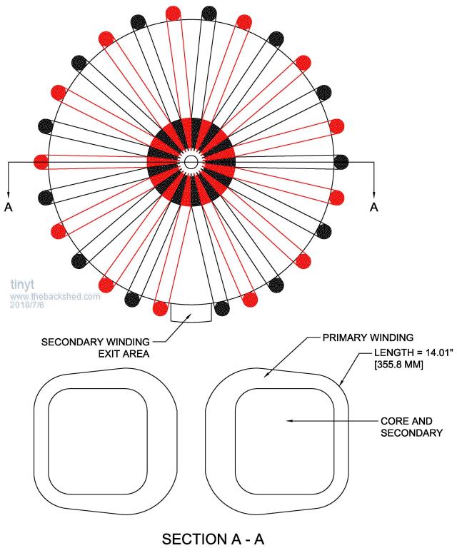


 .
.