
|
|
Forum Index : Electronics : A newbie ozinverter build
| Author | Message | ||||
| tinyt Guru Joined: 12/11/2017 Location: United StatesPosts: 431 |
Pictorial toroid build progress: Here is a picture of the fixtures I used. The 3-post stand is where a put the toroid during winding. 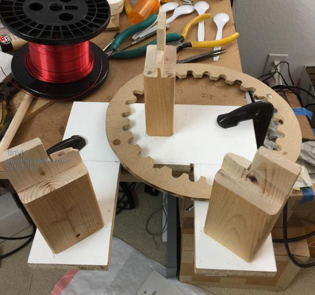 The stand allows better access to the bottom of the toroid. 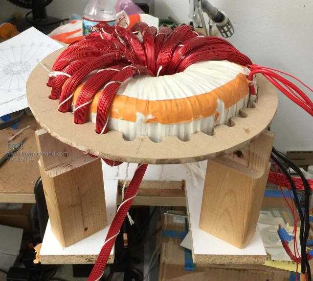 Last 3 turns to go. (toroid top view) 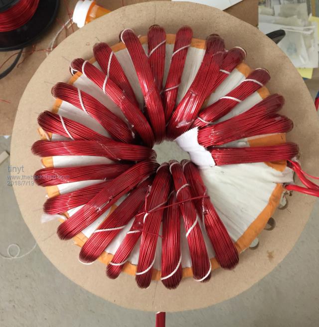 For the mounting bolt insert, I used left over flexible pvc electrical conduit with an OD of 0.82" (20.8mm), I sanded the surface and forced it inside the toroid. Since the pvc is flexible, it became out of round. So, I used an AA size battery, used masking tape to build up the diameter and inserted it in the pvc to restore the round shape. Then I applied epoxy to hold it in place. (toroid flipped for bottom view) 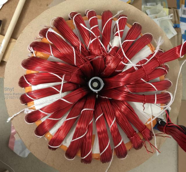 Because epoxy will not stick to pvc, I also applied J-B Weld polyurethane plastic bonder to the pvc insert. (toroid top view) 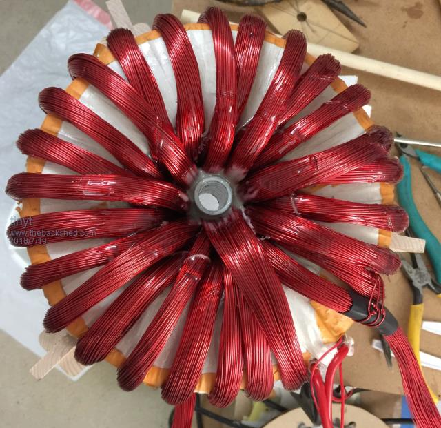 |
||||
| wiseguy Guru Joined: 21/06/2018 Location: AustraliaPosts: 1001 |
TinyT, that is a real work of art, very neat. I bet you breathed a big sigh of relief when the last turn was finally pulled through. You said in an earlier post "so I added a second 12vac winding" Do you have 1 or 2 auxiliary 12v windings ? Are you planning to use it for a direct feedback of output voltage for regulation ? I am still waiting for the rest of my bits to arrive - on a slow boat from china...... If at first you dont succeed, I suggest you avoid sky diving.... Cheers Mike |
||||
| tinyt Guru Joined: 12/11/2017 Location: United StatesPosts: 431 |
Mike, looking in my junk, I found a very small diameter wire and that is what I used for the first 12vac winding intended for regulation feedback. As an after thought, I think I need the feedback coming straight from the toroid because it can be configured either for 115 or 230 vac output. Then later during the wind process, I filled the end gap of the second 115vac winding with the second 12vac winding and this time I found a bigger diameter wire for it. So, I ended up with 2 aux 12v winding. maybe I can use the second one for something or use this second one for regulation feedback. |
||||
| tinyt Guru Joined: 12/11/2017 Location: United StatesPosts: 431 |
Update: Even though the magnet wire I used for the primary is solderable (i.e. no need to strip the insulation), I still stripped each one to make sure that each one gets soldered to the terminal. 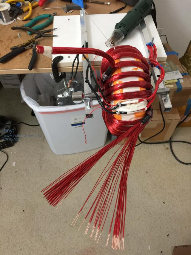 The 110v version of this Handheld magnet wire stripper is what I used. Finally, my electric squash is finished. 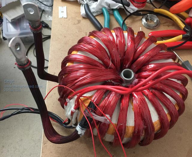 And here is the 'datasheet'. 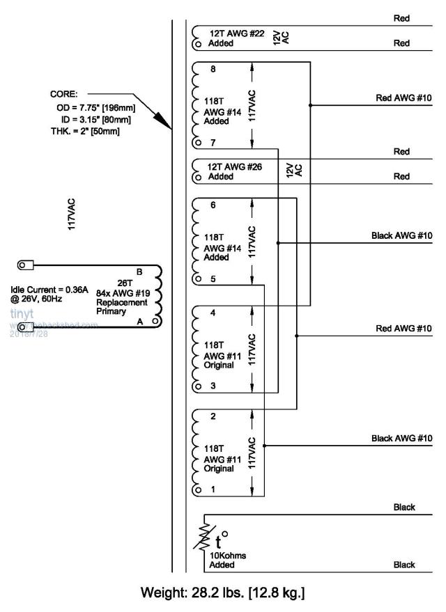 Next: Assembly and hopefully testing. |
||||
| Warpspeed Guru Joined: 09/08/2007 Location: AustraliaPosts: 4406 |
That is a really beautiful job. Well done! Cheers, ĀTony. |
||||
| tinyt Guru Joined: 12/11/2017 Location: United StatesPosts: 431 |
Thanks, but the question of will it work is still un-answered. Hopefully, not too many blown mosfets. |
||||
| Warpspeed Guru Joined: 09/08/2007 Location: AustraliaPosts: 4406 |
Don't know about the rest of it, but the transformer design and construction looks great. Cheers, ĀTony. |
||||
| Tinker Guru Joined: 07/11/2007 Location: AustraliaPosts: 1904 |
You might have none if you follow the methodical setting up I described in the inverter #4 post. You will, of course, have to assume that your PCB functions like mine (or mad's) and there are no assembly errors. My 'designed from scratch' inverters started to work at the first time powering it up, once I got the lowdown how that thing actually works. If you ever bothered to read my early inverter building 'adventures' you will know that it was quite a long road (for me) to figure that out  . .Still, I enjoyed every moment of it and my box of parts for recycling got quite full at one stage  . .Klaus |
||||
| tinyt Guru Joined: 12/11/2017 Location: United StatesPosts: 431 |
Finally had some spare time to continue this project. After reading the wealth of information discussed in Tinker's aerosharp choke thread, I decided to use laminated steel core for the choke. I was able to find from scrap an EI core transformer with a center leg cross section of 1.25" x 2" (31.75 mm x 50.8 mm). Looks like it was vacuum impregnated in varnish and then baked. To salvage the core, I cut the coil: 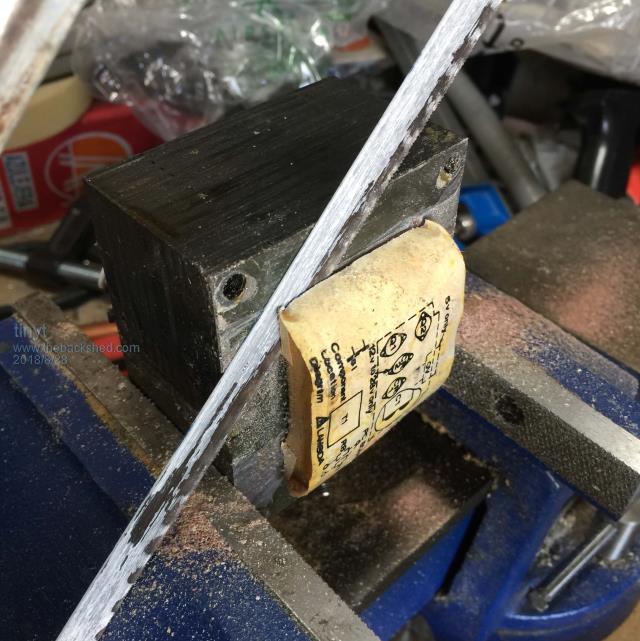 Then removed the rest of the coil from the 'window'. 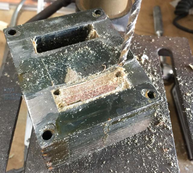 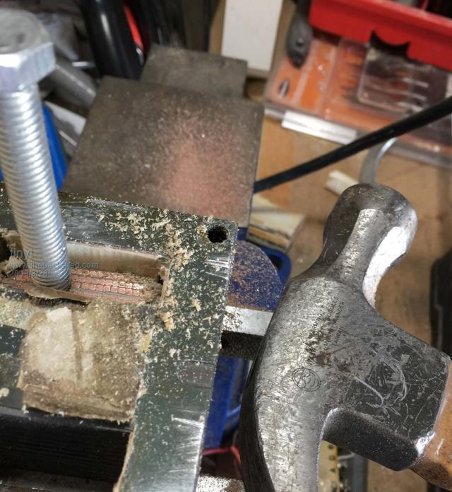 The laminates were grouped into five and stacked in alternating sequence. I used a box knife cutter to separate the stacked groups. 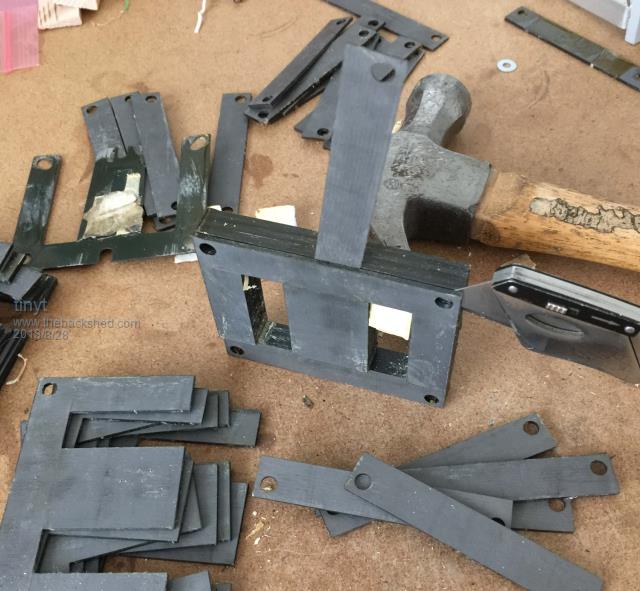 Then I loosely stacked all the E's together, immersed the stack in varnish, clamped them tight and leave them to dry. I did the same thing to the I laminates. 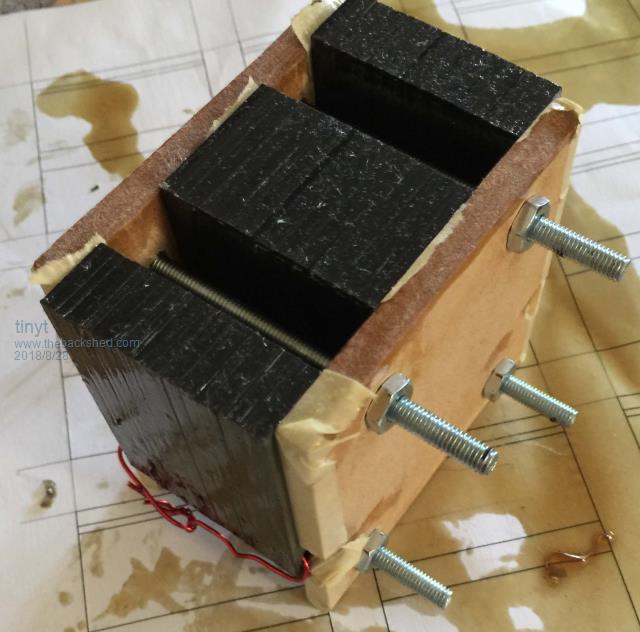 I used the following for the coil form. 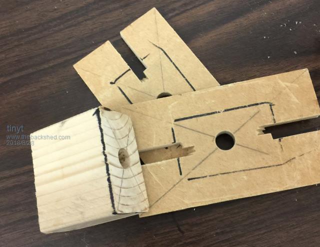 I used transparency film around the core form and mylar tape at the end covers so that the winding can be removed from the form later. Hopefully the epoxy will not stick to the film and tape. 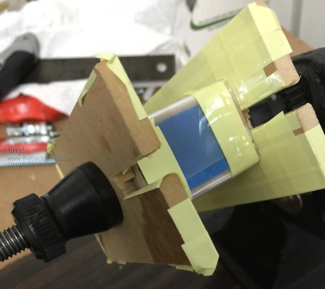 I re-used the original magnet wires I unwound from the toroid transformer that I bought. I first stretched it to remove the kinks. The wire size is AWG #12 (3.31 mm sq.). 19.5 turns fit in one layer. One layer makes one section winding. I used C-clamp to flatten the winding of this layer and every layer. 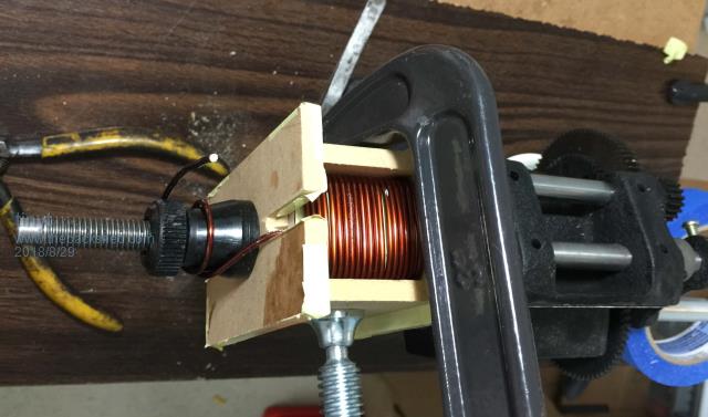 The flattened winding should make efficient use of the available window of the E core. 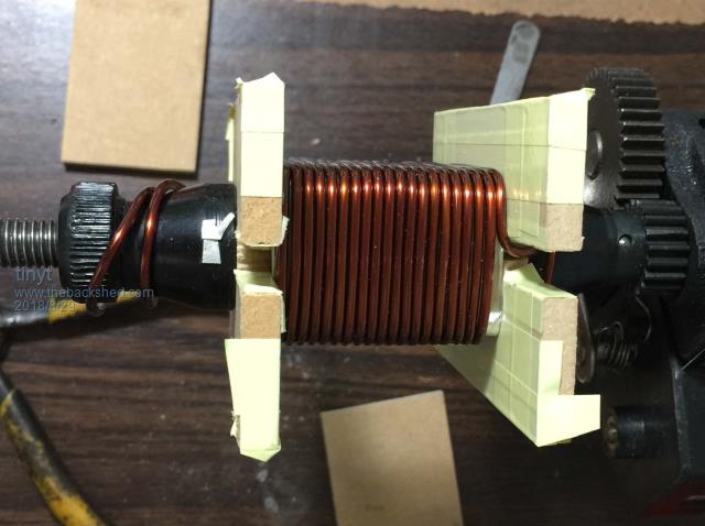 I applied a thin srip of epoxy at the four corners of the winding, so that the wire will not move to prevent the next layer wire to slip in between wires. After the second layer is flattened, I covered the wires with just enough epoxy to hold them in place. I made sure that the epoxy is not to much that it will increase the thickness of the layer. This picture shows the complete six section winding ready for epoxy. 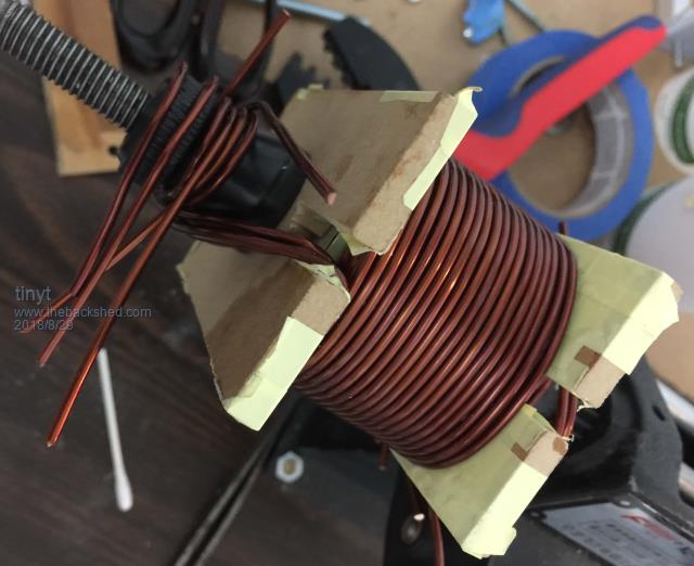 To protect the winding from the sharp corners of the center leg of the core, I covered them with strips of transparency film as shown below. 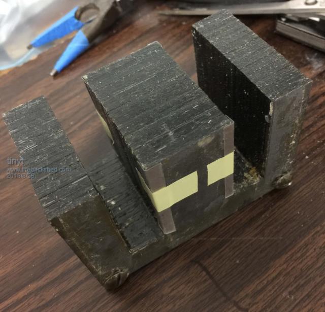 Fit check. 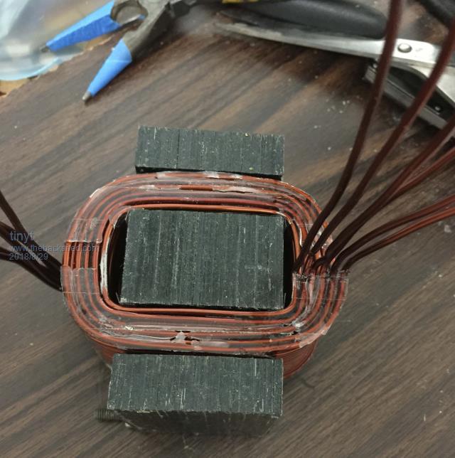 At this stage, I stripped the wire ends, placed the I core on E core legs, applied low ac voltage to one section winding and verified that all the other section windings read equal voltages. Then I transferred the applied voltage to another section and made sure that the first section voltage reading is equal to the others also. Note that the applied voltage will read higher than the others. I found out that this step is important to make sure that there are no shorts. To make sure that the coil does not vibrate, I inserted wooden shims as shown. 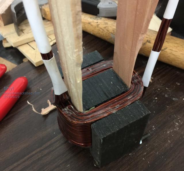 This procedure might be elementary to others, but I just want to document what I did. I hope I am not wasting too much forum resource. |
||||
| Warpspeed Guru Joined: 09/08/2007 Location: AustraliaPosts: 4406 |
A very long time ago I was designing large commercial battery chargers, and still have my design notes for the various sized chokes that I used. One choke in particular used 2 inch wide laminations with an inch and a quarter stack height. The same 2.5 inch cross sectional area of your choke, although the proportions were a bit different. And it used the standard soft iron E and I laminations too, not the grain oriented U cores others on the Forum have used. Anyhow, my choke had 36 turns and a 1.5mm air gap and it produced 1mH and worked up to 85 Amps max. (this was for a 12v 50 amp battery charger). If yours has 19.5 turns and the same 1.5mm air gap it may end up with very roughly about 290uH and 161 amps before saturation. Usual conservative wire current density for transformers might be about 4 amps per mm squared. And that will just run slightly warm with that. Six strands of 3.3mm^2 would be 80 amps but that choke could be safely run higher than that with a bit higher temperature. All going to work out pretty well for you I should think. Cheers, ĀTony. |
||||
| tinyt Guru Joined: 12/11/2017 Location: United StatesPosts: 431 |
Thanks Warp for the very informative comparative analysis. And thanks for the encouraging prediction. |
||||
| Tinker Guru Joined: 07/11/2007 Location: AustraliaPosts: 1904 |
Tinyt, I think you were lucky to get your finish wound coil of your former. Perhaps your thicker wire helped there to, mine was 2.5mm sq. I wrecked one coil by trying to press the wooden former core out. The wire bites into the wood at the corners and locks solid. Think Boa Constrictor  . .For the next one used a plastic core with the same result. Now I only use metal cores, either alu or steel and I make these slightly conical across the wider dimension. This, when pressed from the correct side, pops out the core easily. The other thing I learnt is that stripping the enamel of a bunch of tightly packed coil ends is no fun - I do not possess a fancy stripping machine like yours. So each layer gets stripped & tinned for the start, I use a clamp on the bobbin cheek to hold the ends so its at the correct length already. The end gets treated the same but there no clamp is required as the epoxy holds the turns securely. This does no let me use your shorted coil test method - too hard to keep the short ends apart. Instead I solder the terminals on and then connect the fully assembled choke in series with the earth lead of my AC stick welder. Doing some welding at the 125A setting and then feeling the choke coil if it got warm, as from a shorted turn, showed no problem, the earth lead got warm but the coil did not change temperature. Keep up the experimenting, perhaps you could build the inductance saturation tester Warpspeed described in a thread somewhere - its a great asset to me. Klaus |
||||
| tinyt Guru Joined: 12/11/2017 Location: United StatesPosts: 431 |
Tinker, the wood core former was completely dried out lumber which became very hard, still no match for metal. The corners were slightly rounded. I like your idea of making them slightly conical. What I showed was my second attempt at winding the coil. On my first attempt, I did not use transparency film and mylar but plain masking tape. I could not press out the core also and instead chiseled the wood out from the inside (after drilling more holes). The masking tapes also got stuck to the epoxy. When I tested for shorts, the current draw was too high, 16 amps with the variac at 5vac open circuit. The first layer was reading lower voltage than the others. I thought the core corners were shorting it out, but no it was really shorted turns. When I un-wound and removed that first layer, and re-test, the current draw dropped to 6 amps. Maybe because I used salvaged wires or my winding method, or my chiseling. I don't know. The stripping tool is very useful for large dia. wires. Was suggested to me by somebody in the automatic voltage regulator business. For small diameter magnet wires, I buy the solderable type which does not need stripping, but had to wear mask to avoid breathing what maybe toxic fumes when soldering. That Warpspeed saturation tester is also in my long todo list. |
||||
| Warpspeed Guru Joined: 09/08/2007 Location: AustraliaPosts: 4406 |
Just straight wood almost always causes problems. But if you use an undersized rectangular wooden core, and then build it up to final size, with thin metal packing strips, it then comes apart much more easily. That can all be held together with masking tape, or better still a carefully cut sleeve of large heat shrink. That protects the inside corners of the wire, and stops any epoxy from soaking into the metal packing. To dismantle, just hammer out the wooden core which will slip easily inside the outer metal packing, especially if the packing is made up of several thin layers. Cheers, ĀTony. |
||||
| tinyt Guru Joined: 12/11/2017 Location: United StatesPosts: 431 |
Update pictures, using a total of 16 mosfets instead of the maximum 24: Initial assembly of mosfets to heatsinks. Will be using fabricated heatsink and ebay bought dense fin heatsink for performance comparison. 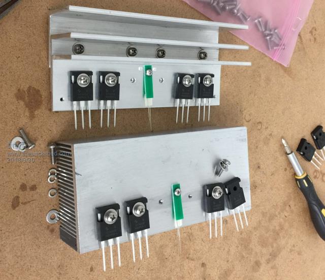 Assembled/soldered the mosfet/heatsink assembly to the CCA (moved the mosfets to the middle of the heatsink). 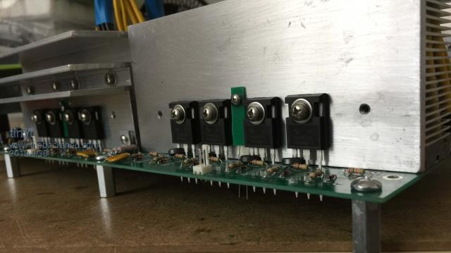 Also used fabricated heatsink for low side mosfets. Will really find out how they will perform during testing. 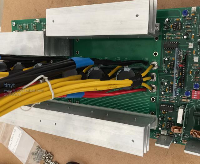 |
||||
| Tinker Guru Joined: 07/11/2007 Location: AustraliaPosts: 1904 |
tinyt, I also have reduced the Mosfet count to 16 on both, my 6KW and the 3KW inverter. That number can handle the asked power easily if they are well matched. And its easier to match 4 than match 6 Mosfets I also have reduced the capacitors to 40,000uF on each inverter. Testing if there is any difference is planned for the next sunny day. That 24 Mosfet idea goes back to when we used TO220 devices with our earlier inverter builds. I think that many is overkill with the HY4008 type. There appear to be a large number of power wires coming off the PCB in your design, there are none at all in mine .Klaus |
||||
| tinyt Guru Joined: 12/11/2017 Location: United StatesPosts: 431 |
Yes, the mosfet voltage drops were all very close to each other when I individually tested them. On the next PCB design, I will also reduce the HY4008 count. I used multiple automotive AWG #10 (cross section = 5.25 mm. sq.) for the power wires. These wires are available at most auto parts supply stores here. The plan was to test different heat sink types so I made all power wire connections to the PCB instead of to the heatsinks. Also connections are spread out on the PCB copper surface to minimize current 'hot spots'. Wire count is: 12 for Battery Plus (equivalent to 63.12 mm. sq. or about 8.9 mm. dia. single wire) 12 for Battery Minus (equivalent to 63.12 mm. sq. or about 8.9 mm. dia. single wire) 9 for each Mosfet bridge outputs. (equivalent to 47.34 mm. sq. or about 7.7 mm. dia. single wire) |
||||
| tinyt Guru Joined: 12/11/2017 Location: United StatesPosts: 431 |
Since I cannot get a suitable in-expensive steel cabinet, I am making a wooden one  . Outside dimensions are 24" x 24" x 8" (610 mm x 610 mm x 203 mm). Picture is partial construction, back panel is already painted, exhaust vents are not yet done, so are the other cut-outs. . Outside dimensions are 24" x 24" x 8" (610 mm x 610 mm x 203 mm). Picture is partial construction, back panel is already painted, exhaust vents are not yet done, so are the other cut-outs.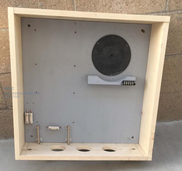 I am going to install it to an outside wall of the house shaded from the sun. 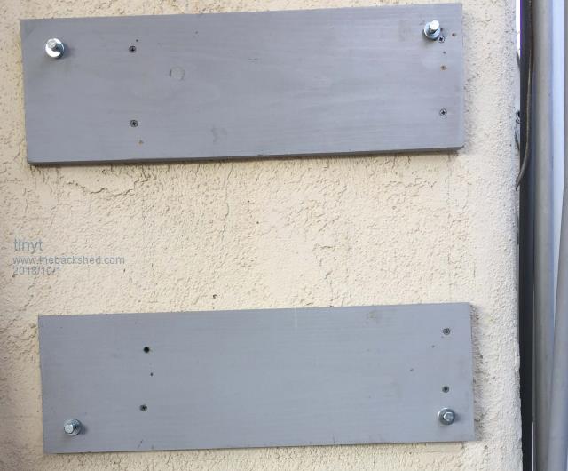 The inside of the cabinet will be lined with aluminum sheet to minimize radiated EMI. The aluminum sheets will also make it fire retardant for several seconds (I hope). Picture is corner of back panel with the aluminum sheet glued using contact cement. To extend electrical connection with the side panel aluminum sheets, I covered the edge of the back panel with kitchen aluminum foil. 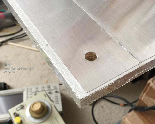 |
||||
| tinyt Guru Joined: 12/11/2017 Location: United StatesPosts: 431 |
Some preliminary assembly: 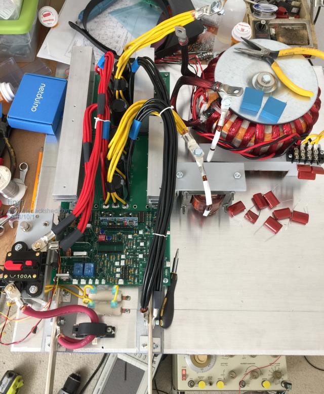 I used a 'scope and sine-wave generator with a 47K series resistor. With the toroid secondary wired for 230vac, the capacitor for 90Hz parallel resonance is 2.7 uF (2.2 uF in parallel with two 1.0 uF that are in series, they can be seen connected in the picture). With the toroid secondary wired for 115vac, the capacitor for 90Hz parallel resonance is 20 uF (two 10 uF in parallel, they are the blue parts on top of the toroid clamp disc). I have an old RLC meter and measured the capacitors and they are close to the rated values. I measured the inductance of the toroid secondary and came up with 354 mH for 230vac connection and 80 mH for 115vac connection. When I used the values in an online parallel resonance calculator, I did not get 90Hz. Still investigating. My resonance test or the inductance measurement or both are probably not correct. |
||||
| Warpspeed Guru Joined: 09/08/2007 Location: AustraliaPosts: 4406 |
Don't worry about getting it absolutely perfect, its going to change a bit anyway with different types of non linear and reactive loads connected to the inverter. If you can just get it fairly close to 90Hz it will work fine. Cheers, ĀTony. |
||||
