
|
|
Forum Index : Electronics : A newbie ozinverter build
| Author | Message | ||||
| tinyt Guru Joined: 12/11/2017 Location: United StatesPosts: 431 |
OK, will not spend more time on this for now. Thanks Warp. |
||||
| Tinker Guru Joined: 07/11/2007 Location: AustraliaPosts: 1904 |
When you start testing it with big loads keep a sharp eye on the heavy wire bundles. They will move about, I noticed a single thick primary cable move when I turned on a big load. With a bundle of wires secure strapping might be required. Another idea for your home made heat sink trials. Can you get aluminum (your spelling  ) flat bar in 3/8 x 4" size? You can tap that easily for your Mosfets and attach smaller (1x1x1/8") U channels for fins at the other end. ) flat bar in 3/8 x 4" size? You can tap that easily for your Mosfets and attach smaller (1x1x1/8") U channels for fins at the other end.You want a big thermal mass right at the mosfet to suck away any heat pronto. Only thick material will do that in my experience. BTW, your inverter case looks very sexy. Klaus |
||||
| tinyt Guru Joined: 12/11/2017 Location: United StatesPosts: 431 |
I will secure the wires after I got it working. But I don't know if I can test it with big loads, I don't think I can afford that much batteries and also wind a bigger toroid. Here is a cross section of the heatsink/mosfet assembly right now. 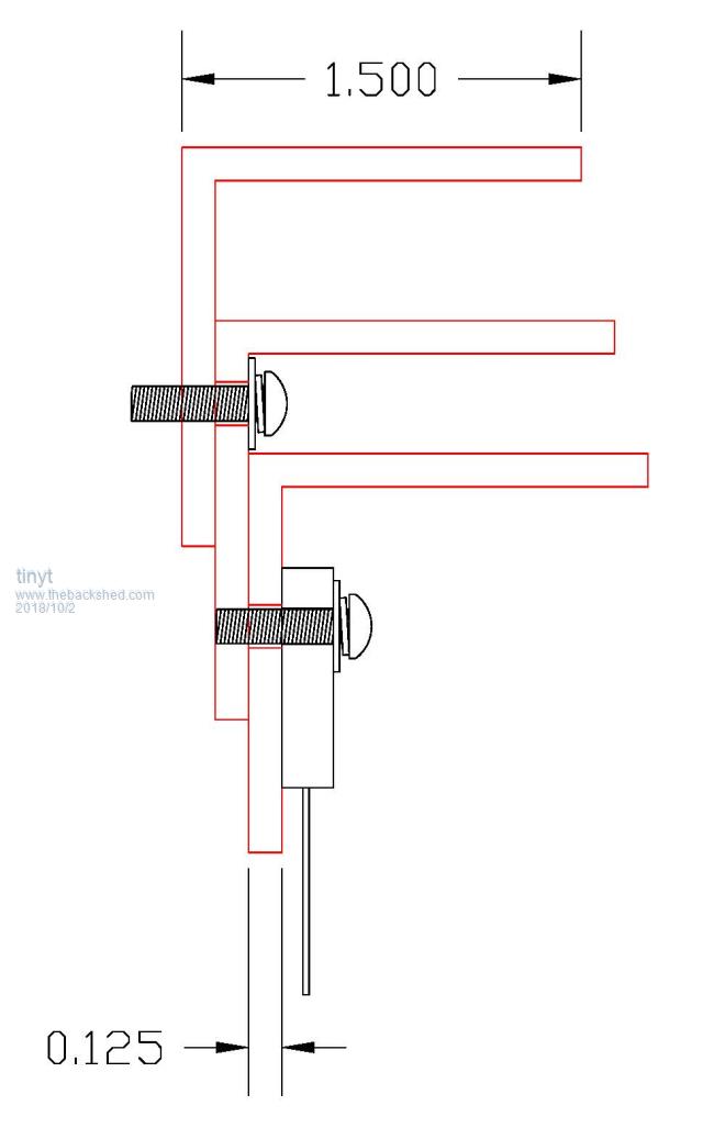 I might try your heat sink suggestion later. I think I can get the flat bars and U channels here from Almost Anything Supplier Thanks for your suggestions Klaus. |
||||
| tinyt Guru Joined: 12/11/2017 Location: United StatesPosts: 431 |
Re-did the 90 Hz resonance test and for the 230vac output connection, the capacitor came out to be 3.7 uF. Re-jumpered the EGS002 for 60Hz. Adjusted the VFB trimpot for 3.0vdc when toroid output is 230vac (used variac for this). Used 1.5mm air gap on the EI choke, and the 3.7 uF tuning cap. Connected the toroid and choke and applied power using my bench top power supply at 53vdc - NO SMOKE, re-cycled every 10 seconds the SPWMEN signal switch, still no smoke. I am pleasantly surprised. Output reading is 226vac - good enough for me. With no toroid load, current draw from the power supply is 0.38A (20.14 watts idle power). Waveform looks like this. 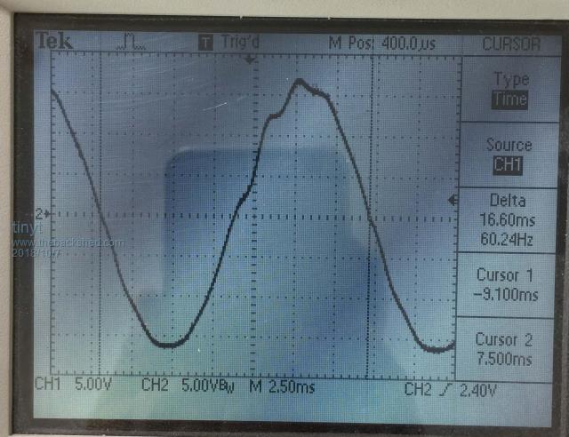 I changed the capacitor to 2.2uF, current draw from the power supply is 0.35A (18.55 watts idle power). Waveform looks like this. 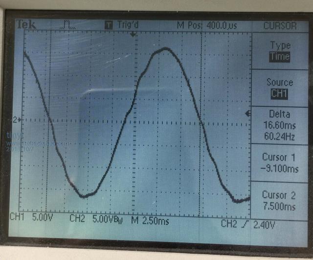 I changed the capacitor to 1.0uF, current draw from the power supply is 0.34A (18.02 watts idle power). Waveform looks like this. Kink appears near zero crossing. 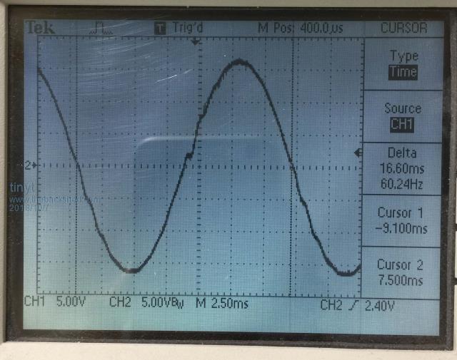 Maybe if PWM mode is bipolar, the waveform will look better, but it is good enough for me right now. I will be using the 2.2 uF capacitor for an idle power of 18.55 watts. |
||||
| Warpspeed Guru Joined: 09/08/2007 Location: AustraliaPosts: 4406 |
The idling power is excellent. Waveform is pretty good too. The transformer does seem a bit lively which suggests the choke is working very well at isolating the transformer from the bridge, that 2.2uF seems about right. I would expect that some small resistive load will damp down that liveliness and smooth out the waveform. There is always likely to be some small residual load on the inverter anyway. Try it with a 60 watt light bulb as a load and see how that looks. All together a very pleasing result. Well done ! Cheers, �Tony. |
||||
| tinyt Guru Joined: 12/11/2017 Location: United StatesPosts: 431 |
I don't have a 220vac incandescent lamp. But I have a 220vac 1.2kw stove heating element I bought for testing. Here it is powered by the inverter. Could not keep it powered for too long in the house, have to make a better testing setup outside the house. 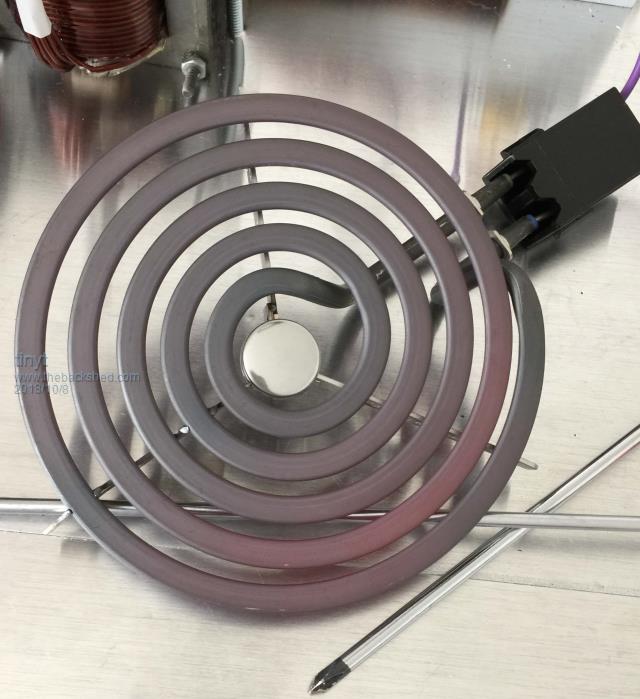 Here is the waveform. 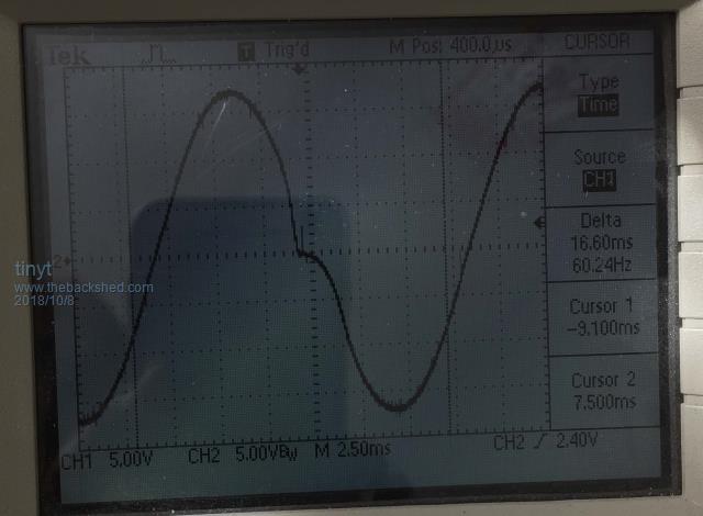 Here are the basic readings: DC input: 53.8V, 25.28A (53.8 x 25.28 = 1360 watts) AC output: 229V, 5.25A (229 x 5.25 = 1202 watts) Loss: 1360 - 1202 = 158 watts Efficiency: 1202/1360 = .8838 or 88.38% I am guessing that the loss is mostly in the choke which has smaller copper wire cross section compared to the toroid and power wires. I also have to measure voltage drop in the 100A switch if any. Will do more testing later. |
||||
| Warpspeed Guru Joined: 09/08/2007 Location: AustraliaPosts: 4406 |
That 158 watts will all show up as heat somewhere, so whatever gets hot will be where your losses mostly are. Not sure why only the negative half cycle has that discontinuity, the waveforms at the bridge might tell us something. Cheers, �Tony. |
||||
Madness Guru Joined: 08/10/2011 Location: AustraliaPosts: 2498 |
Something is not right, you should be getting a good waveform no matter how much resistive load you have. I would be quite concerned with that result. My experience with power losses in the Inverter is around 8 - 10 percent. There are only 10 types of people in the world: those who understand binary, and those who don't. |
||||
| Warpspeed Guru Joined: 09/08/2007 Location: AustraliaPosts: 4406 |
Agree something is not quite right, and as its not symmetrical so not likely to be a problem in the magnetics. Use the 5K1/0.1uF low pass filter suggested on page six of the EGS002 application notes to look at the waveforms coming straight out of both sides of the mosfet bridge . They should look exactly like the waveforms shown. https://www.egmicro.com/download/EGS002_manual_en.pdf Looking at the waveforms directly with a digital oscilloscope will just show meaningless garbage. You need to have the low pass filter to average out the high frequency pwm so you can see the 50Hz component. Cheers, �Tony. |
||||
| tinyt Guru Joined: 12/11/2017 Location: United StatesPosts: 431 |
First some clarification to avoid confusion. My toroid has two 12vac windings. One I used for the VFB and other I used for scope waveform monitoring. In my earlier no load resonance test, the 'scope ground and probe is opposite to the connection I made for the 1.2kw load test. So here is that resonance test waveform again with the scope connection matching with that of the 1.2kw load test. It shows the kink starting to appear in the negative slope of the waveform. 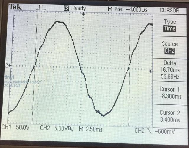 Looks like it gets more pronounced when the inverter gets loaded. Here is the scope with top trace for the toroid primary connection driven by the 60Hz side of the bridge. The lower trace is the other end of the primary coil driven by the choke. This is with 1.2kw load. 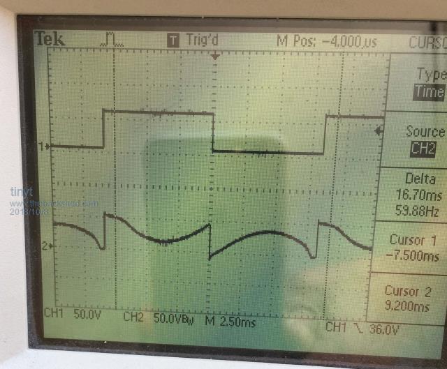 Unfortunately, I don't have a 'scope that can capture each of the 23KHz pwm pulse duration. Looks like the discontinuity is being introduced by something inside the EGS002. Maybe the anti cross-conduction transistors are not matched. I don't know. Will use another EGS002 later and see. Or bypass the anti cross-conduction transistors and pray. |
||||
| Warpspeed Guru Joined: 09/08/2007 Location: AustraliaPosts: 4406 |
The sine wave side is definitely distorted around the zero crossing points. Using the same R/C low pass filter look right at the pins of the EGS002 board and see how it looks there. If its suspect there, I would try removing those cross conduction transistors and see if that looks any better. Cheers, �Tony. |
||||
| Madness Guru Joined: 08/10/2011 Location: AustraliaPosts: 2498 |
What does it look like at the output of the EG002? I would think it is more likely to be something to do with your gate drive. There are only 10 types of people in the world: those who understand binary, and those who don't. |
||||
| wiseguy Guru Joined: 21/06/2018 Location: AustraliaPosts: 1017 |
Apologies the post has moved on from when I wrote this. You are on the right track. What I wrote was - it may still help if the EGS002 waveform is right- Looks like you will receive a cross section of ideas to draw from. Looking at the RC filtered fundamental shape from the EGS002 is an easy test, if it passes then what? From inspection it appears that one or maybe more of the drive waveform is not correct at one part of the cycle at the zero cross. I suspect the 25kHz side but dont dismiss the 50/60 fundamental stage yet. I would do a couple of preliminary checks. With power disconnected, remove the drive cable from the output stage and check gate to source resistance of all 4 sections of the H bridge measures ~5K (1/4 of 20K). Then a resistance check of all D-S are essentially open circuit (note use a meter with a < 0.4V test for the ohms range. Then check using the diode test that D-S of each leg is open in one direction and ~ .3 - .5V in the other direction. If all is ok reconnect to driver board' With the H power (48V) disconnected, ground the centre of the bridges allowing the upper FET bootstrap sections to have power and then use simple CRO comparisons between the EGS002 SPWM1-4 outputs and the corresponding final Gate drive outputs (after the output buffers) look nearly identical. If all Ok continue.. The next checks are whilst the Bridge stage is powered up & waveform distortion is present and therefore inherently risky. Check the 12V & 17-18 V rails are present and not sagging with a CRO. If the bootstrap rails are sagging near the zero cross a CRO is the best method of checking. An isolated CRO is a must and simply connecting it across the upper bootstrap capacitors, one at a time and ensuring the voltage never drops below 10V. ( It shouldnt drop below ~ 15V in your setup working correctly I reckon). I would expect somewhere along this path you should identify something amiss ? Good Luck - it is best to follow the order presented, powering the bridge stage again only at the final step, impatience can be dazzling. If at first you dont succeed, I suggest you avoid sky diving.... Cheers Mike |
||||
| tinyt Guru Joined: 12/11/2017 Location: United StatesPosts: 431 |
Found my R/C probe. Here is EGS002 pin 8. 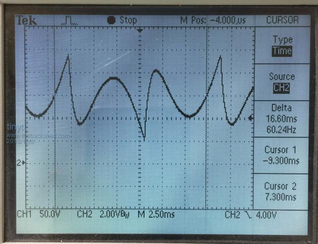 And EGS002 pin 10. 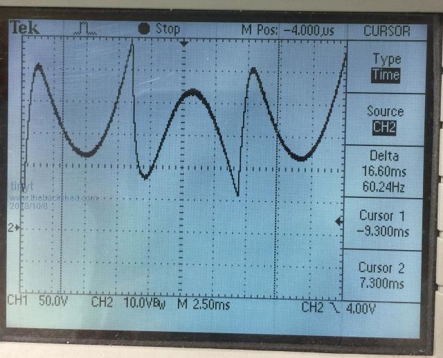 The waveform looks similar. But what I notice is the negative peaks only go to 2V instead of zero. So I checked my schematic. The actual fet drivers are IR2010PBF which are driven by the IR2110S in the EGS002. Pin 8 and 10 of the EGS002 goes up to 12V instead of 5V. Edit: -> (I think my analysis here is wrong) -> So I added voltage dividers. I was thinking that maybe the EGS002 is not pulling to zero the IRF2010PBF due to the voltage divider effect. So I added diodes as shown. 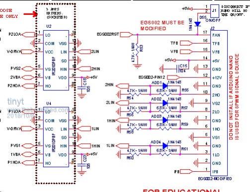 And setup to test. As the saying goes if it can happen, it will happen. I have a test connector with a thin black wire connected to PCB ground. The 100A switch is at off but the 100A power supply which is connected to the battery bus bars is running. When I was going to connect the test black wire to the scope probe ground wire, it slipped from my finger and the exposed wire strands touched the live 54vdc connector. 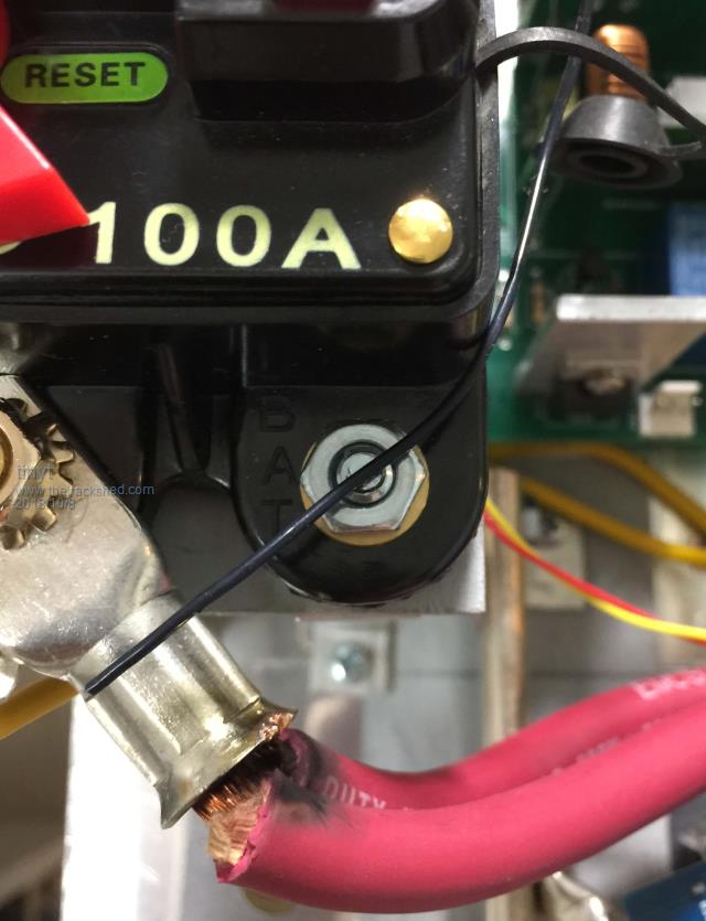 The exposed wire strands were vaporized. (I already cut the burned end in the picture). Initial tests indicate that not all grounds are connected. I have to remove PCB from the chassis and do more post-mortem. I think this qualifies me to join the exclusive club.  Thanks to all for the troubleshooting assistance. Over and Out (for now). |
||||
renewableMark Guru Joined: 09/12/2017 Location: AustraliaPosts: 1678 |
Oh c'mon mate, one bit of singed wire? You haven't even blown a fet yet. Not in the club yet mate. BTW that breaker/switch you have are often dubious quality, keep an eye on it. Cheers Caveman Mark Off grid eastern Melb |
||||
Ralph2k6 Senior Member Joined: 24/09/2017 Location: AustraliaPosts: 129 |
Mark / tinyt Narva sell those breakers, only rated to 48v max I think. Breaking a fault with fully juiced batteries would be over 60v ?  Ralph |
||||
| Tinker Guru Joined: 07/11/2007 Location: AustraliaPosts: 1904 |
Ralph has a point there if these things were used as breakers. I use them too but as high current DC switches. There are proper DC breakers inside my inverters and these, being rated lower amperage, will do the tripping if required. But for a simple high current switch see pic below how I use mine. 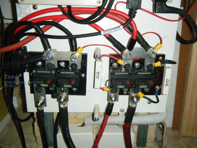 Note that there are 4 of these things. Two are in the negative and 2 in the positive inverter connection, serving my two inverters. Note also that the two positive switches have the soft capacitor charge resistor across the terminals. With this set up I can: Completely disconnect each inverter to remove its power cables without having to isolate the lugs at the end since the other end lug is at the open circuit breaker. Soft charge the capacitors by first closing the negative switch and then, once the green battery light (on my type control board) comes on, close the positive switch. The inverter can now be soft started by its ON switch. This might be a bit of an over kill but for an experimenter it has proved invaluable. A suggestion to tinyt - it apprars he has those breakers on his PCB. This is, perhaps, not the best location for them. Mine are on the wall close to the battery bank which is to the left on the pic above. Klaus |
||||
| tinyt Guru Joined: 12/11/2017 Location: United StatesPosts: 431 |
Klaus the breaker is not mounted on the PCB. Here is a close up of that area of the assembly. 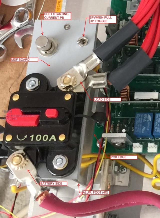 It also has a LED indicator (the unlabeled round part between the PB and Toggle) to signal that there is 5VDC on the PCB so that the breaker can be switched on. Here is my understanding of voltage rating of switch/breaker contacts. If switch loads are not capacitors, when the contacts break, the full dc voltage appears across the breaking contacts and an arc will form and will get extinguished if the broken contacts have enough final gap to do it. So, the higher the voltage rating, the bigger the final gap of the contacts should be when they open. In my application, the load are bulk capacitors that get fully charged to the applied voltage when the breaker is switch on. So when the breaker contacts separate, at that moment, both sides of the contacts have zero volt difference and no un-wanted arc will form. Add Edit: That EGS002 pin 10 waveform I posted earlier is incorrect. I think that is for the boosted fet gate drive, I don't remember anymore, I was taking too many pictures. I will have to revisit the waveforms after I fixed the PCB. They don't exactly match with what is shown in the EGS002 data sheet. Also, I think that EGS002 datasheet waveform is taken straight from the EG8010 pins or outputs of the anti cross-conduction transistors and not the EGS002 connector TEST pins, the peak-to-peak is only 4 volts. |
||||
| johnmc Senior Member Joined: 21/01/2011 Location: AustraliaPosts: 282 |
tinyt congratulations, for your efforts constructing the inverter. I have not had any trouble with AC, MCB breaking the 48v circuit under load . But the AC, MCB will fail ( fuse the contacts together) if you try to switch on the 48v supply, to charge the main inverter capacitors. cheers john johnmc |
||||
| tinyt Guru Joined: 12/11/2017 Location: United StatesPosts: 431 |
Yes, that is why I have a momentary push button that soft-charge the bulk capacitors thru a resistor prior to switching on the 100A circuit breaker. On the inverter, I still have to make it work correctly. Lucky me I still did not qualify to join the exclusive club. |
||||
