Notice. New forum software under development. It's going to miss a few functions and look a bit ugly for a while, but I'm working on it full time now as the old forum was too unstable. Couple days, all good. If you notice any issues, please contact me.
nickskethisniks Guru Joined: 17/10/2017 Location: BelgiumPosts: 462
Posted: 08:47pm 29 Apr 2018
Copy link to clipboard
Print this post
Good evening!
Today I had the chance to make further progress on the inverter. I did assemble the control board without any problems, although I'm missing the thyristor for the overcurrent section. Apparently I forgot to order it...
So, I did test the board, all signals were perfect. I connected it to the powerboard were I allready soldered the caps ( I know, not verry wise..) and soldered 4 mosfets. I will
Testing was done with a few sla batteries, but I forgot to disconnect the charger, the charger dc current was not isolated, so my scope probes were... . Not good when you want to test the high side signals...
That way I destroyed one mosfet driver and 2 mosfets...
I repair electronic devices for a living so I had to know...
Well it's working... Although I have one problem (I think), I didn't connect the voltage feedback (yet). But the pulses were not going away (good for testing though), it stayed working, is this normal?
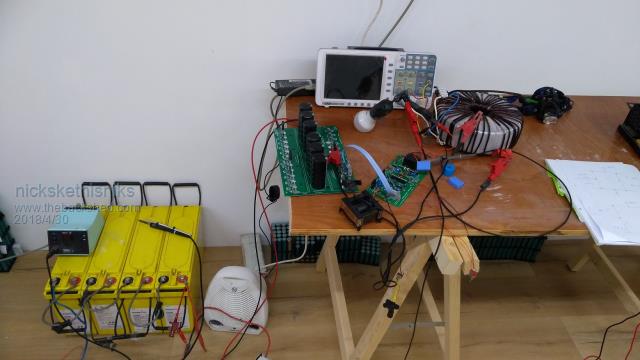
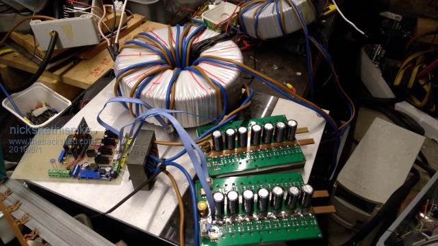
So here the testing rig:
Next step, choosing the output filter cap and the filter coil. I've tested with 3 turns around a ETD59 N97 ferrite and an 1uF capacitor, that gave me a decent sinewave, I will add another capacitor. I think the core sufice for the kind of power, I designed it for 2000VA, but number one is the low idle power, it will be used for lights. But it will be used for power tools and induction motors during the build of the house.
The above testing is with the 2000VA core, it runs a 6W led bulb with 15W incoming power, I will do more testing next week.
Madness Guru Joined: 08/10/2011 Location: AustraliaPosts: 2498
Posted: 09:16pm 29 Apr 2018
Copy link to clipboard
Print this post
Good that you got it working and know what caused your failure. If you cut the earth pin off your CRO power cord it will help a lot with isolation issues.
Testing without caps is a good idea but if everything is correct then it will work. You could add heatsinks now and test with at around 1200 Watts. If you are using HY4008W MOSFETs I would not put more than 4 in, going above that has caused problems for some of us due to insufficient gate drive.
Interesting that your inverter will build a house I will be doing the same soon also.Edited by Madness 2018-05-01There are only 10 types of people in the world: those who understand binary, and those who don't.
oztules Guru Joined: 26/07/2007 Location: AustraliaPosts: 1686
Posted: 11:01pm 29 Apr 2018
Copy link to clipboard
Print this post
I have to disagree with you Mad I think your confusing feelings with facts, and so is tinker.
All the theory in the world is useless when it come to real world physics. No matter how good the theory seems... if the real world disagrees with it, then you must change that theory.
I know you think you solved your blow up problems by using the totem pole driver... but the sad truth is that that DID NOT SOLVE IT!!!
To you it seemed to be a happy coincidence that using that stopped the blow ups... but that cannot be what really transpired. I don't know what you were doing wrong, but it was not lack of driver.
Years later most of the units in the field are still of the 4110 vintage . driving 6 fets, with NO repeat strongly... NO ill effects. So that appears to be a crutch your using. Something else was wrong... I wish I knew what, but I was not there.. but I can tell you with utmost certainty, and years of real life in field testing in many locations... the 2110 will drive 6 4110 or 4 hy4008... standing on it's head, and not fail in real world applications.
I don't know how else to say it, but, you had some other problem , which appears to be solved because of the totem drivers.
I'm happy that something worked for you, as you plodded on tirelessly, and that deserved a result.
Thats not to say I think it is useless, I think it is better than no totem, but if your failing with the totemless boards, totems aren't going to help you if you've built it incorrectly ( whatever that means... we'll never know what was causing you grief now)
I can't have mine working flawlessly, and yours working ditto, if that was a critical difference... or even a useful difference. 4 x hy4008 has less capacitance and more current carrying than 6 x 4110... but both work perfectly.
The inductors.... tinker spent a goodly amount of time trying all manner of inductor, thinking that was his problem..... no it was not the problem, never was never will be.
Millions of inverters of this design are in operation all over the world under the W7, powerstar, and a myriad of other manufacturers, including Power Jack NONE OF THEM USED INDUCTORS on their units. And they were devastatingly reliable and powerful (Powerjack not so much, their trannies were too small) Most used EI transformers, with low grade steel, and plenty of leakage, but they still worked awesomely.
I bought a 6kw powerstar first, and you can drive anything you dream up, they are incredibly powerful... no inductor, 2 amp drivers, 6 mosfets.... and they just work perfectly well.
It was not until I talked to PowerJack, that they started to put in some inductance in the transformer lines, and they just used little torroids placed on the leads.
This was for idle current mitigation... nothing else. It did not need anything else ( apart from bigger torroids perhaps).
My powerstar used 5kwh/day without the inductor. The inductor made no discernable difference to operation... only idle current... thats the practical real world outcome.. no more no less. Anything else we read into it is just piffle.
Yes it may have some acedemic advantage, but in practical terms, this is what we measure. Does it pull 18kw... yes... did it fix the idle current ... yes.... did it do anything else useful.... who knows, who cares.
So we must be careful to take the right lessons from what are shown in the real world, and try to avoid extrapolating that into a legend without legs.
Nick... 1. you can run 4 x hy4008 perfectly well with what you have. Totems are a luxury that will make no practical difference... I like them anyway, but no practical difference.
2. If you can run without the ac input beware of over loading the fets, as the wave will be fully opened to max, and depending on your setup, could be fatal. Some times you get away with it, sometimes you don't. If it does not turn off after the 3 seconds, it is simply a different batch number of 8010. They work the same, just no uvlo.. no idea why... luckily, the 8010 dynamics are limited, so you may get away with it sometimes.
3. Do not put loads more than 500w when no caps. The shoot through spikes will likely kill the fets. The caps are there for a reason. You can run small power without them, but not much. I limit it to 350w for that testing... or the inductive reactance has no quenching.
4. Use o/load in the b+ line when testing. Any blow up then will limit the damage to the fets only as a general rule. I use 68amp AC mini contactors from a normal switch board. The fets won't burn, just blow the contactor. Beware that a full bank of caps can burn up over 400 amps of inrush, and fuse the contactor shut if you don't use a current limiting scheme to charge them up. In the field I run 2x68a o/loads.
5. Slow charging of the caps will lead to the 8010 hanging, so resetting it is usually required. I short the 120r to ground on the tip35 side to achieve this. Mad has had a bad experience with this, I never have. He must have some instability in there somewhere, but this works on all the units I have (about 18 units now), but if you have an isolator of some type to cut the power to the control board, and reconnect it again, it will probably do the same thing.
So, all the theory in the world won't fully explain what is happening all the time, but this is what works in the real world. Others have had experiences different to me, but generally on only a unit or two, mine spans many many units under all circumstances, so I believe this to be a better perspective of what works and what is superfluous to simple operation.
Don't get me wrong, I do like the changes Mad has done, the fancy inductors that tinker has built... but in the end, they are not critical to perfect operation in any way.
The only thing I have found lacking in mine, is the uvlo for low battery, and even here it is speculation on my part. I have no proof that this is what blew up two units, but flat battery was the common denominator, and theory says that if voltage sags, current goes up..... but still it is only my theory that thats what killed them. ( they ran for years until that long bout of dark weather )
Different transformer inductor arrangements may be why all the others units out there have been rock solid. I have no proof either way, but uvlo is good for the battery at least. Mad has solved this nicely I think... I have yet to bother, but I should. It has been years since any other failure of any kind has occurred in any installation, so there are many many operation years combined in all the units I have in the field now... probably 40 or more.
This post won't win any friends, but had to be said. You can't base too many conclusions on one or two events... suspicions yes.
So inductors won't save a badly built machine.... and nor will totems affect the control board if built correctly, and wired correctly... and I can attest that sloppy wiring does not seem to be too problematic either. In some of my testing rigs (photo's somewhere ) the units are spread over the bench far and wide, and still worked perfectly.... and this amazed me.
..........oztules
Village idiot...or... just another hack out of his depth
yahoo2 Guru Joined: 05/04/2011 Location: AustraliaPosts: 1166
Posted: 11:53pm 29 Apr 2018
Copy link to clipboard
Print this post
I faffed about looking to see if static discharge was the cause, I know other mosfet drivers have been discontinued and superseded because they are very susceptible, no idea. I'm confused, no wait... maybe I'm not...
Madness Guru Joined: 08/10/2011 Location: AustraliaPosts: 2498
Posted: 01:55am 30 Apr 2018
Copy link to clipboard
Print this post
Oz I appreciate your input, recently I tried bypassing the Totem Pole drivers on one of my power PCBs. It caused issues, put them back and it worked again this is with one of your latest version control boards. I have some IR2010 driver chips here that I plan to try without the totem pole and see how that goes. They are 3A rather than 2A output with a maximum voltage of 200.
I am at loss as to what else can be different to what you are doing but my experience has been 16 FETs works more becomes unstable with spikes and failure. Since adding the Totem poles it works and works well.
There are only 10 types of people in the world: those who understand binary, and those who don't.
oztules Guru Joined: 26/07/2007 Location: AustraliaPosts: 1686
Posted: 02:41am 30 Apr 2018
Copy link to clipboard
Print this post
"I am at loss as to what else can be different to what you are doing but my experience has been 16 FETs works more becomes unstable with spikes and failure. Since adding the Totem poles it works and works well. "
I am at a loss too. All the units out in the field that have 4110's are 24 fets, all the hy ones are 16 fets... all work swimmingly... so who knows why.
.......oztulesVillage idiot...or... just another hack out of his depth
Tinker Guru Joined: 07/11/2007 Location: AustraliaPosts: 1904
Posted: 09:02am 30 Apr 2018
Copy link to clipboard
Print this post
Thanks oztules, your lengthy post re possible inverter failures is much appreciated.
Constructive criticism is what I like here on this forum, makes me think about different ways of doing things and why. Never been afraid of learning something new. After all, I knew BA about inverters before I started following this forum.
Since I now have two very neat inverters, running with the totem pole drivers and working well in 24/7 use, I got plenty of time for more experimenting.
Perhaps one day I will find that critical component or arrangement that *must* be right for the thing not to blow up .
I re located a little home etched 4 Mosfet test board I made last year, this one uses TC4452 drivers. The next few days should show me why I had given up on that (forgot now ) for the totem pole driver idea. I have a little toroid from a junked Latronics 48V/ 1200VA inverter which is perfect for testing purposes.
Suspecting you are right that its not the drivers that caused madness & myself problems, my experimenting with 3 different kinds should verify that to me.Klaus
nickskethisniks Guru Joined: 17/10/2017 Location: BelgiumPosts: 462
Posted: 07:09pm 30 Apr 2018
Copy link to clipboard
Print this post
Thank you for all the input guys.
Keep reminding this: "Electronic problems are easy, it's always something".
The only reason I bought the book with the boards is because I'm building a house by myself (and my wife) so I have to little time to design the inverter by myself. So I wanted something straight forward. I like designing boards but I always keep changing the design so I never finish something...
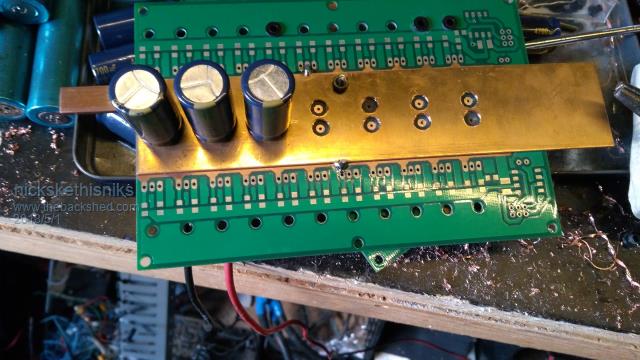
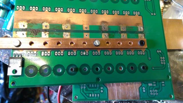
This was something I didn't finish (yet): Designed for a bldc controller but it's also suitable for an inverter, but it's impossible for cycle by cycle current measuring and soldering busbars is verry difficult, and once cooled down, the pcb is misformed.
Edited by nickskethisniks 2018-05-02
nickskethisniks Guru Joined: 17/10/2017 Location: BelgiumPosts: 462
Posted: 01:20pm 23 Oct 2018
Copy link to clipboard
Print this post
UPDATE:
Just going on with constructing the house, so very little time. But I completed the control and powerboard, and I'm now fixing and testing the bugs.
I'm using 24 mosfets and the IR2010 mosfet drivers.
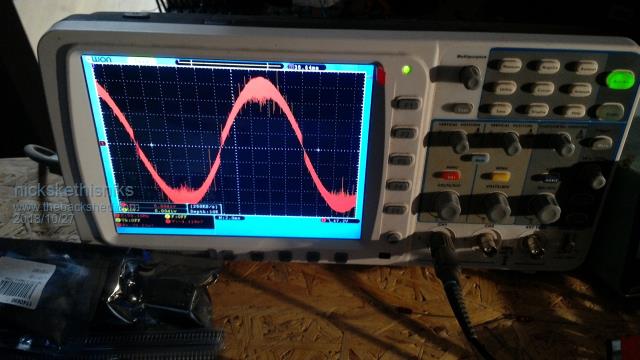
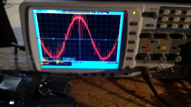
The first test with 24 mosfets was done with a 2000VA transformer but it made a terrible noise and waveform, despite the serie coil (50uH, etd59 with 1.6mm airgap).
The no load primary current was more then 2A so something was wrong. The same story with a smaller 160VA EI transformer.
So tested the gate pulses and the problem was in the high side sine pwm. I think the 13V for the mosfetdriver was not enough, I also saw a small ripple on the 13V line. So I started using a dcdc capable of 15V 750mA. This solved the problem for now. I also added a ceramic capcitor (100nF) over the 10uF bootstrap capacitor in the gate drive.
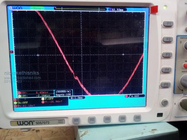
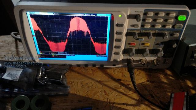
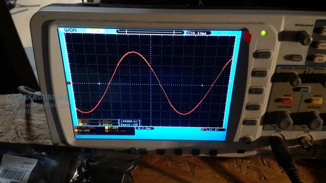
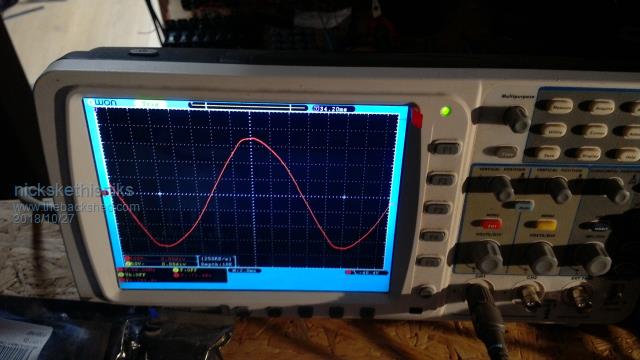
But I still have a woble caused by the same high side sine pwm, this can be seen on the scope screen. It's presented when using 0,47uF or 1uF at the 230V side. When using 2uF I think it's gone.
So the question is, do I need to worry, and do I need more adjustments in the control board? The tests were done without voltage feedback.
Edited by nickskethisniks 2018-10-24
nickskethisniks Guru Joined: 17/10/2017 Location: BelgiumPosts: 462
Posted: 07:00am 25 Oct 2018
Copy link to clipboard
Print this post
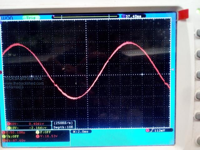
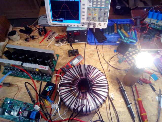
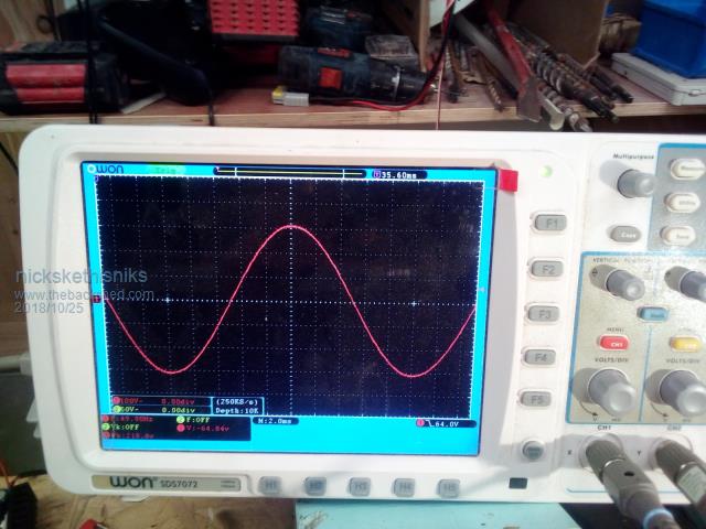
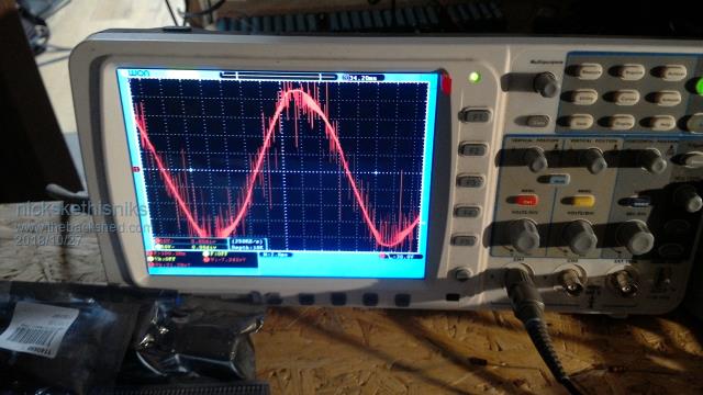
I saw that others had the same scoop images, I tested everything verry good so I finaly dared it to test the toroidal 2000VA core with voltage feedback.
So I made some time to do testing although I need to adjust the current cut off and the final filter choke and remove a few more turns on the primary for higher output voltage under load.
So I tested the 2000VA core, ( isolation transformer with primary and secundary in series, and a new 48V winding)
The zero load @ 230V output is somewhere around 9.5-10W and that is with voltage feedback adjusted for 230V output.
Loadtest:
Output 40W --> 74% Output 56W --> 80% Output 966W --> 91.6% Output 1599W -->89.2% (output was only 211V (47Vdc in), I need to remove a few turns)
Testing was done with a resistive heater and a 40w halogen bulb and an old 48V 92Ah SLA batterypack.
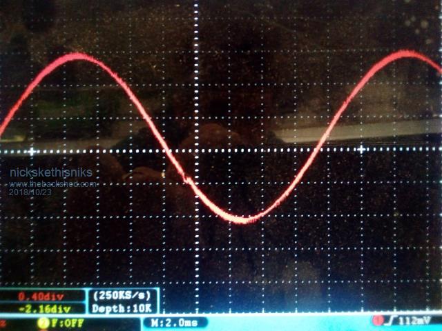
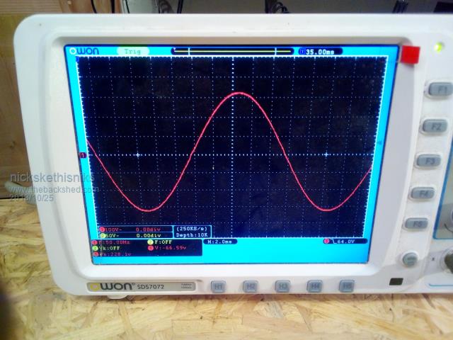
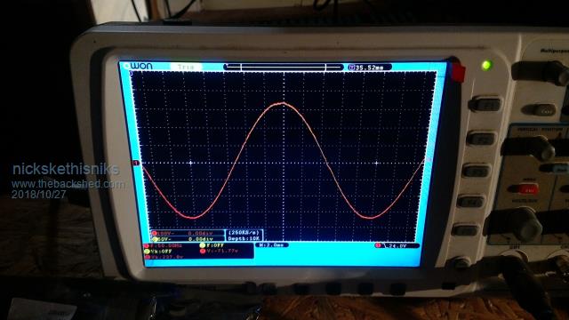
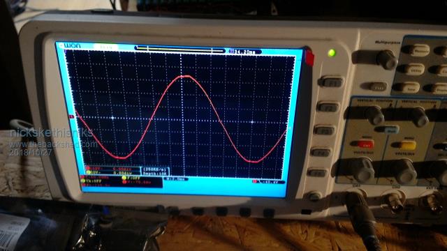
I think it's a good result, I use 2uF output and 50uH filter choke. The output sinewave looks verry clean as well. It's good for medium loads, I still need to test induction motors, like cuttoff saw.
I had to make the following adjustments:
-voltage feedback resistors -gatedriver voltage -->15V -I use 24 irfp4110 mosfets -I use IR2010 gate drivers -I use chinese dcdc 48-->15V 700mA and dc/dc 48V--> 5V 200mA
I think it's a good result, I use 2uF output and 50uH filter
The high side sine pwm 23khz driver is getting warm but not hot, is this normal? The 50hz side is ambient temperature.
Testing:
1599W
966W Edited by nickskethisniks 2018-10-26
johnmc Senior Member Joined: 21/01/2011 Location: AustraliaPosts: 282
Posted: 09:34pm 25 Oct 2018
Copy link to clipboard
Print this post
sine wave looks good You should very pleased with the results.
cheers johnjohnmc
noneyabussiness Guru Joined: 31/07/2017 Location: AustraliaPosts: 526
Posted: 09:38pm 25 Oct 2018
Copy link to clipboard
Print this post
Not sure if you know, but the 13v zenner on clockmans boards needs to be replaced with a 18v zenner...but good jobb all the same, the grid is much worse a lot of the time..Edited by noneyabussiness 2018-10-27I think it works !!
nickskethisniks Guru Joined: 17/10/2017 Location: BelgiumPosts: 462
Posted: 10:55am 26 Oct 2018
Copy link to clipboard
Print this post
I can always adjust the output voltage of my dcdc to 18V but it would not give me more current gain.
If I make the comparison between the IR2110 original used in the Oz inverter and my IR2010 driver, there is not much gain in using the IR2010, next time I better use the IR2110 with higher voltage.
One important comparison
IR2110 * 18V --> 3A gate current capability * 15V --> 2A gate current capability
IR2010 * 18V --> 3,5A gate current capability * 15V --> 3A gate current capability
So with my 15V and IR2010 I'm at the same level as the IR2110 on 18V. But the IR2110 is 1,62€ and the IR2010 is 3,52€ a piece!
In the meanwhile I did the finetuning of the smaller transformer, just need to make an inductor saturation meter for making an apropriate inductor.
The next step was defining the number of windings in the bigger transformer before I start winding the massive wire. I did testing with a flexible 10mm˛ wire, I need between 19 and 20 turns.
Testing results: zero load 0,37A @ 49V output +- 18,1W I think I could improve this further with a better inductor better output filtering? I'm using 2uF output capacity.
tinyt Guru Joined: 12/11/2017 Location: United StatesPosts: 441
Posted: 12:52pm 26 Oct 2018
Copy link to clipboard
Print this post
Hi nick, your numbers and waveform look great to me. In the picture, are you using a ferrite choke and an EI laminated choke in series?
nickskethisniks Guru Joined: 17/10/2017 Location: BelgiumPosts: 462
Posted: 08:10am 27 Oct 2018
Copy link to clipboard
Print this post
Ok, I meant no load 18,1W with 230V output...
The other inductor is a ferrite with 213uH, and is rated at 40A I think, I was lucky to find it somewhere in a scrap container.
What I did noticed was that with the 213uH the output voltage was around 235V instead of the 230V with the 50uH choke.
I did not (yet) make a combination of the 2 choke's in series.
I think the higher inductance is making a nicer sinewave at the primary(48V), but I'm not sure because it could also be the hihger or lower saturation current...
nickskethisniks Guru Joined: 17/10/2017 Location: BelgiumPosts: 462
Posted: 08:04am 28 Oct 2018
Copy link to clipboard
Print this post
Can someone advice me about the EI laminated choke? I have EI steel from salvaged transformers/inductors. What I have is 35mm wide and 25mm wide (the midle leg), I can make it as wide as needed. What is the cross section I'm looking for, with the big transformer I'm looking for 9000VA nominal (1u use) and 20kVA peak. The smaller one needs to handle 2000VA and 4kVA peak
At the moment I have something put together with 35mm*90mm cross section, it's about 4Kg iron, I can increase that if needed. The iron came from 2salvaged 160VA transformers, but I have more... :).
Thanks!Edited by nickskethisniks 2018-10-29
nickskethisniks Guru Joined: 17/10/2017 Location: BelgiumPosts: 462
Posted: 07:23am 12 Nov 2018
Copy link to clipboard
Print this post
Pff, can't make a decent choke. The best choke I have is around 50uH with Ferrite core, the others have a higher no load current, even a combination of the two... The best EI iron choke was also 50uH and was 0.6A no load. 0.35A is the best no load with Ferrit choke. Higher induction is not better in my view. The 50uH iron choke gave the best sinewave on the input off the transformer because there was no saturation at all! But the 50hz hum is enormous @ only 2000W! But the voltage rised up tot 241V ( setting is 230v).
I'm going to stay away from the iron choke for now, and I will just try to make a non saturation ferrite choke with a decent current rating.
I plan a test with a ferrite and iron core with 50uH in Total, see what that gives me. But the battery is low (again) from my induction meter. Edited by nickskethisniks 2018-11-13
poida Guru Joined: 02/02/2017 Location: AustraliaPosts: 1432
Posted: 08:15am 12 Nov 2018
Copy link to clipboard
Print this post
I only use ferrite cores in my chokes. I am convinced iron core chokes in this application (quenching large amounts of MHz energy) is a poor choice.
So, I give my vote for a large ferrite core inductor, tested to large currents to prove no saturation. A little more or less idle current is not so important. Avoiding replacing blown MOSFETs is the thing to consider.
....and some here have had great results from iron core inductors in this application. I have not. I stopped having to replace MOSFETs are I started using the large TDK E70 cores, with an air gap.wronger than a phone book full of wrong phone numbers
renewableMark Guru Joined: 09/12/2017 Location: AustraliaPosts: 1678
Posted: 08:38am 12 Nov 2018
Copy link to clipboard
Print this post
Well I can't explain why but the iron one I made with Warpspeed worked brilliantly, saturation is well past 100A, then it got put in series with a double stacked E70 ferrite, this appears to be a great combo.
Poida, don't forget you were using the Ali exp inverter boards, not the Mad boards, so you can't really compare, perhaps your problem lay with them???
My Mad unit is approaching 700kwhr of production without the slightest hiccup. I run the house totally off grid now, everything is powered by the madinverter. I cringe at what my wife does, but I don't tell her off any more, the aim is to have the house basically the same as what the grid will do, so trust me the machine has copped a bloody hiding. Oven on, AC going and then do some vacuuming.
Poida, it's very unusual how you and Warp have such different views on iron cores, perhaps re visit the idea when you have the Mad power board operating.
BTW if anything about my setup makes you curious you are more than welcome to come by with your scope to check on things... and have a beer of course.Edited by renewableMark 2018-11-13Cheers Caveman Mark Off grid eastern Melb
nickskethisniks Guru Joined: 17/10/2017 Location: BelgiumPosts: 462
Posted: 08:37pm 20 Jan 2020
Copy link to clipboard
Print this post
Hello,
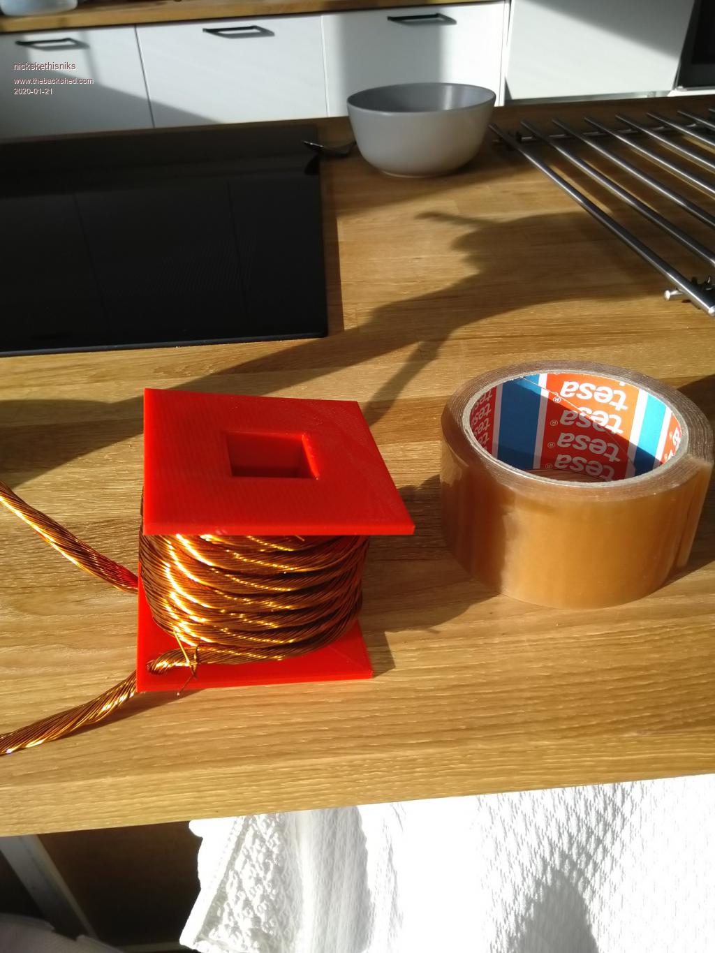
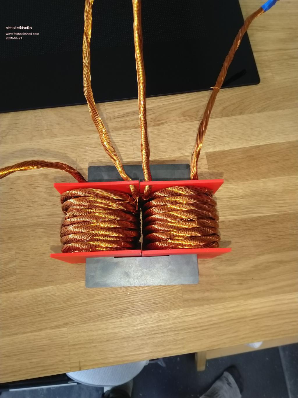
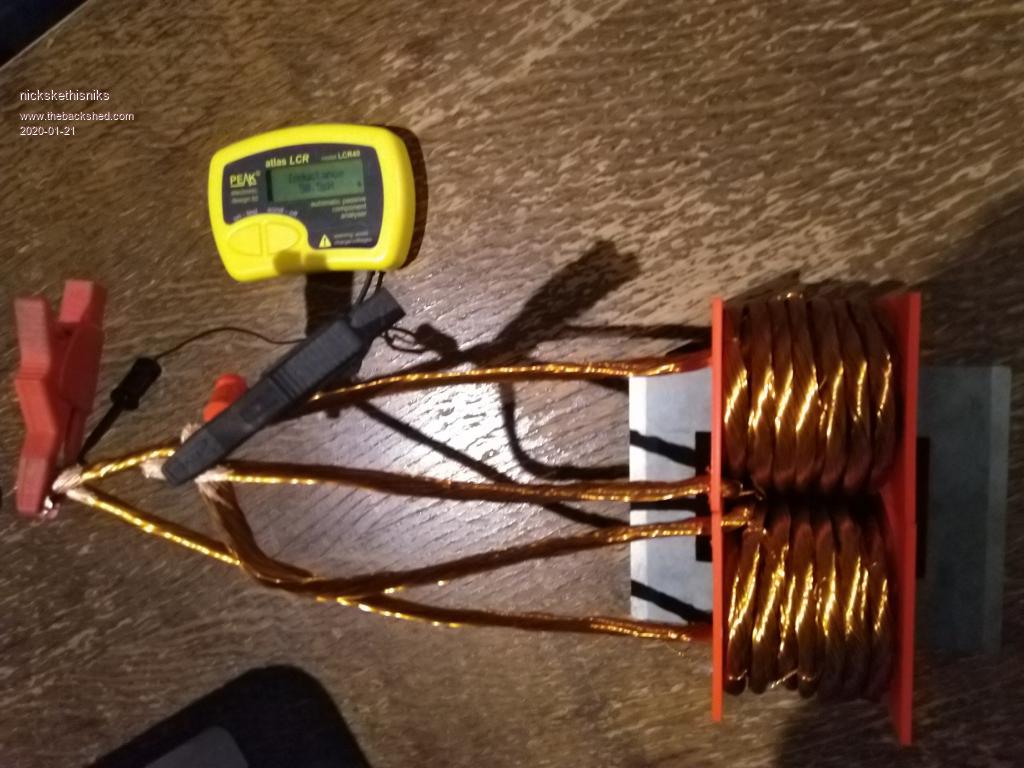
Another attempt in making a good sized inductor for my inverter. My current inductor has only that 10mm˛ wire and is on his last breath. They epoxy has a hard time when my wife find the power outlets. One time It got really smokey arround the inverter...
So I need advice, I have those really nice cores, https://www.ferroxcube.com/upload/media/product/file/Pr_ds/U100_57_25.pdf
and a coworker of mine, made some coilformers with his 3D printer. So it let me make 2 bobins with each about 25 turns (not quite sure). Each with 60 strands of enamelled wire, good for 60A each. So should withstand 120A in parallel. As an aircoil they have 23.8uH each what I find quite high but that's what the lcr meter says.
So with the core (2 halves) in place it's about 375uH, with one half it's 30uh, I need to have an airgap around 15mm to get my 50uH. Before I solder lugs on it, would this kind of inductor work? I joined the wires that way the 2 bobbins are acting like one bobbin.
It's the airgap that troubles me, I'm not confident about that, isn't it to much. I know I could allways remove some turns, but I prefer not to do that. Than I will use it in another project, in my solar buck converter for example.
I have another set of coilformers and cores, so I could make more.
During previous testing it was 50uH that worked best, 200uH gave to much distorted wave forms. So I'm aiming for 50uH.
So would this type of inductor "setup" work or do I look for something else? I'm not looking for high saturation
Here some pictures:
Edited 2020-01-21 06:54 by nickskethisniks
Page 2 of 3
Print this page
The Back Shed's forum code is written, and hosted, in Australia.


 no idea.
  .
. ) for the totem pole driver idea. I have a little toroid from a junked Latronics 48V/ 1200VA inverter which is perfect for testing purposes.
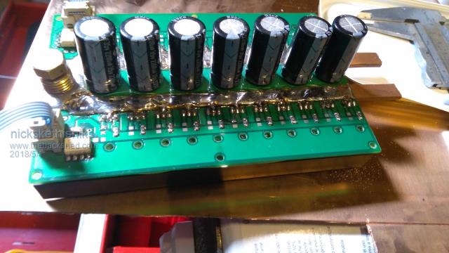

 One time It got really smokey arround the inverter...