
|
|
Forum Index : Electronics : Another Inverter Build
| Author | Message | ||||
renewableMark Guru Joined: 09/12/2017 Location: AustraliaPosts: 1678 |
Yeah, that will work, jaycar have the cable fittings, got the packet here, the side entry type is PS0984 8304 LABELLED SKT LINEIDC 10WAY. Edit, hey Rev, if you are going to make the cable yourself you may as well buy new cable, only $1.85M here Just rip off 6 so you have 10 plug youtube Cheers Caveman Mark Off grid eastern Melb |
||||
| johnmc Senior Member Joined: 21/01/2011 Location: AustraliaPosts: 282 |
Good Day Revlac Thanks for the scope picture , will be taking more pics when I get my inverter control operating again. some of the rain you are getting is needed in northern victoria Cheers john johnmc |
||||
Revlac Guru Joined: 31/12/2016 Location: AustraliaPosts: 961 |
Bit of an update, the IDC cable went together OK, the connectors I used have gold plated socket inserts and have spring steel catchers on the sides to hold it all together, I have not seen any like that on sale anywhere just all plastic ones. Next time I go to Ipswich I can drop into jaycar and grab some new cable, connectors and other things. Just finished populating the power board with all the components apart from the fets and caps, all the joints looked ok and inspected for anymore potential shorts all looking good. Next I thought it might be a good idea to check over every solder joint with the multimeter and sure enough there was a bad contact/dry joint which was not visible, even the meter did not pick it up at first, it was firm but could lift the resistor out of the solder joint without to much effort. knowing this may well have lead to an untied fet gate which would most likely end up blowing up the the fet and a few other components as well.  My previous inverter build I busted quite a few fets and I'm almost certain most of it was caused by dry joints. So I would think that if the component's all check out properly and in good order and the control board is working correctly and the power board is checked over well (leave nothing to chance) we should be able to just assemble the thing and it should all just work, I think do it properly and it might just save us a lot of PAIN trying to find what went wrong and how afterwards... Wishfull Thinking.  Almost ready to give it a test run with one fet per leg, no caps and I think not load it any more than say 100w total to keep things safe. Just another thought when we test the inverter the first time most of us have different battery capacities and could be close or some distance from the main battery bank and different size battery leads, it was suggested to me some time ago that when running with long battery cables it may be good to twist the battery cables around each other 1 or 2 times to help stop noise on the DC side.? Cheers Aaron Off The Grid |
||||
Madness Guru Joined: 08/10/2011 Location: AustraliaPosts: 2498 |
Well done finding the bad joint Aaron, could have resulted in a lot of hair pulling later. Having good solder joints is critical, I was fortunate to have had soldering lessons from a former NASA Engineer when I was studying Elec Eng. They had to be very careful with how much solder they used in every joint to keep weight down. One failed MOSFET means a lot more go at the same time as they are constantly playing Russian Roulette with their opposite. I know Oztules uses a current limiting power supply for testing, but the 2 33 OHM resistors in parallel I use work fine. I have never had a component fail when using that and no caps. However, it does not take much load to cause problems with voltage drop while running via the resistance. Once it is up and running and looks good I then turn on a 20A Breaker so the resistance is eliminated. Then I can turn on a 1200W fan heater with just 4 HY4008s and no caps. The Sinewave starts to become triangular though with that load and no caps. I know you are running off grid Aaron, I had waves within the Sinewave of my inverter while testing, it turned out to be caused by my old Trace Inverter. There are only 10 types of people in the world: those who understand binary, and those who don't. |
||||
| Revlac Guru Joined: 31/12/2016 Location: AustraliaPosts: 961 |
I have been thinking it should be fine if I keep the voltage above 40v for testing, shouldn't be to hard with an appropriate series resistor. Most likely I will test and use this one in the shed rather than use the existing setup that is running the house. This also makes me think about the voltage drop when starting large motors/power tools and things, only have a set of truck batteries in the shed ATM and 3kw of solar, so far it can handle 100Amp surge without dropping the voltage to low. Something els that might be of interest: The 4 pack of HY4008W is a lower price per piece compared to others eg. the 20 pack or even the 10 pack. Now I don't know what will happen at the checkout? but to me it looks cheaper to get 10 packs of 4 (over 10 shipping is more $$$) than 2 packs of 20? Perhaps I have not looked at it properly and haven't seen the BS yet. Take a look and see if it makes sense... Cheers Aaron Off The Grid |
||||
| Madness Guru Joined: 08/10/2011 Location: AustraliaPosts: 2498 |
Sometimes the shipping method is different, once over a certain value Aliexpress require them to use tracking. In that cause you break up the order and pay for one then do a fresh order. There are only 10 types of people in the world: those who understand binary, and those who don't. |
||||
| Revlac Guru Joined: 31/12/2016 Location: AustraliaPosts: 961 |
Had a little time this afternoon, So its about time to power this inverter up without caps and see if it works. Looks like a good wave and a decent length soft start.  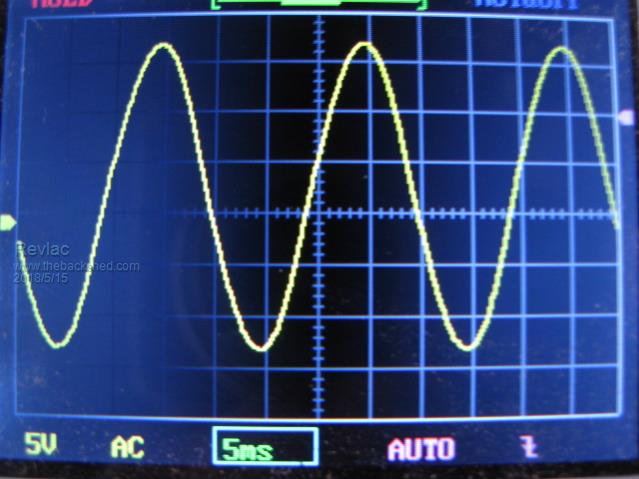 The only issue that has cropped up is the output voltage is adjustable but far to low under 190vac, I'm still testing using the old EI multi tap tranny and I probably used the wrong tapping, on the primary side, the voltage is 20vac should be higher than that. The feedback transformer is 12v but only putting out about 10vac, I was sure I used the 3K9. I would take a guess and say there is too much voltage getting back to the VFB and that would be holding it back.? And the fact that the EI tranny is only using about 8Watts from the 50v battery bank So it is not being driven high enough. Will have a look at it tomorrow. Cheers Aaron Off The Grid |
||||
| Madness Guru Joined: 08/10/2011 Location: AustraliaPosts: 2498 |
Try a 7K5 resistor, I am using one with my latest build and it gets up to 230VAC. There are only 10 types of people in the world: those who understand binary, and those who don't. |
||||
| Revlac Guru Joined: 31/12/2016 Location: AustraliaPosts: 961 |
Will do.  Found These 80v 10000uf caps seems to have a good rating, But still nothing wrong with a good set of 100v ones Cheers Aaron Off The Grid |
||||
yahoo2 Guru Joined: 05/04/2011 Location: AustraliaPosts: 1166 |
I need some of your MAD skills. I have got a Marantz amp receiver on the bench I am avoiding, it has a board with sprung/ cracked solder joints from being flexed when it was screwed down in the factory. it is going to be a real stinker. A good 2 hours to get the board out and I think I am going to need to build a custom soldering iron with a elbow joint.I'm confused, no wait... maybe I'm not... |
||||
| Madness Guru Joined: 08/10/2011 Location: AustraliaPosts: 2498 |
Such a shame you are so far away my eyes are not as good as the used to be. Although being very short-sighted I can get very good vision at about 100mm with no lenses in the way.There are only 10 types of people in the world: those who understand binary, and those who don't. |
||||
| Revlac Guru Joined: 31/12/2016 Location: AustraliaPosts: 961 |
Thanks oztules For the post on the long ON/OFF switch leads. These long leads I was using where causing some horrible erratic crackling noises in the choke and the EI tranny. Fixed now ( bypass the 1k to ground), and putting decoupling caps ( 104 and a 10uf ceramics). This kills the interference that can get into the switch lines if they are long.... Just had to duck outside and do this mod. Photo quality is a bit.sad 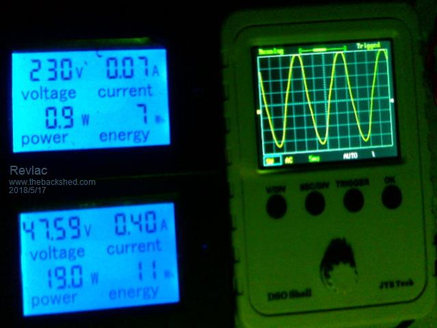 Now working much better. Also changed the 3K9 to 4K7 for VFB, for some reason 3K9 or 7K5 did not get within the range I wanted, will investigate why a little later. Cheers Aaron Off The Grid |
||||
oztules Guru Joined: 26/07/2007 Location: AustraliaPosts: 1686 |
Your welcome Aaron, Marks problems were able to help someone else... good thing. Amazing how you learn nothing if nothing goes wrong. I have never had a problem since I ran with the above board configuration. I did not know I had beaten a problem I didn't know existed.... Although I did find out about the sensitivity, but I assumed it was with the resistor configuration I was trying for single pole switching. Did not try spdt switching at that time..... and when I did, it was above board. I do use quite long lead for the switching now, and I use high power... something is going my way apparently. Your wave looks good enough for prime time. ........oztules Village idiot...or... just another hack out of his depth |
||||
| Madness Guru Joined: 08/10/2011 Location: AustraliaPosts: 2498 |
Johnmc might benefit from this also. There are only 10 types of people in the world: those who understand binary, and those who don't. |
||||
| Revlac Guru Joined: 31/12/2016 Location: AustraliaPosts: 961 |
Started working on a box to put all the inverter parts in, cleaned up the rust cut some holes for the gauges to sit in, Must remember to plug up all holes to stop any of the critters getting in. 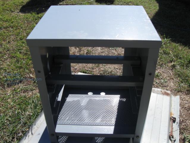 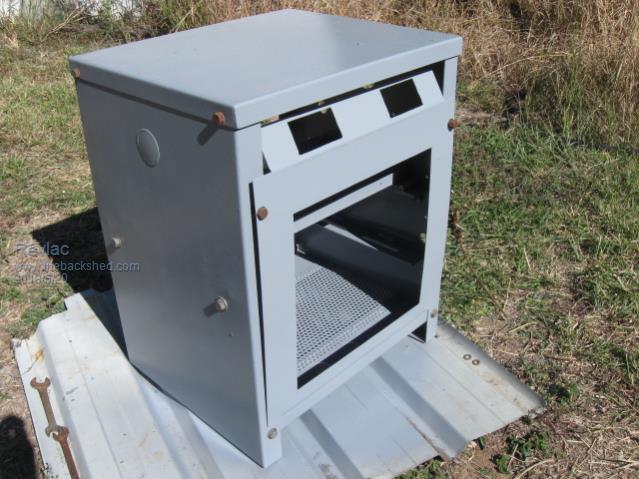 The transformer also scrubbed up nicely and should fit in the box with rubber mounts and enough room for anything els. 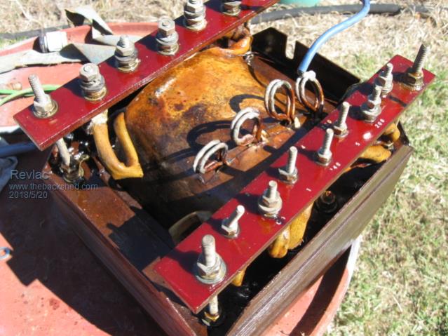 At the same time I am also working on a larger one as parts turn up. Is there any difference between the 4UF CBB61 and CBB65 Motor start/run cap apart from the shape, voltage and that some have wax in them. I ask because there are plenty of the CBB65 types around in florescent lights and small motors, shame to waste them, can they be used as a filter cap for the inverter or is there something els different that I'm not aware of.? Apart from the obvious. I think I have answered my own question.... Cheers Aaron Off The Grid |
||||
| Revlac Guru Joined: 31/12/2016 Location: AustraliaPosts: 961 |
Well Today was not much good all round by the looks of things. I Just had the 2 pip inverter's blowup late this afternoon, and been trying to do some repairs in the dark until I fired the old Genny. Both inverters blew up at the same time, half the bridge smoked out on each, they where not linked in any way, all separate apart from running off the same battery bank. So how/why this happened I don't know yet, I guess that it is not a good idea to have more than one inverter per battery bank. Some more incentive to get on with the inverter build. Cheers Aaron Off The Grid |
||||
| Boppa Guru Joined: 08/11/2016 Location: AustraliaPosts: 814 |
You too?? (I was the only tech at my old company that could field repair our SMD pcb's- because I didnt need a microscope/magnifier, just looked over the top of me glasses up close and personal) was very handy |
||||
| Revlac Guru Joined: 31/12/2016 Location: AustraliaPosts: 961 |
Well I have successfully repaired my farther's pip4048HS inverter, a bit of a challenge. 8 of the high side fets were blown,legs off and smoked, cracked and some of the SMD gate drive resistors/components were fried and replaced. I found that there was no damage past the totem poll drivers, good. The buck converter was also stuffed 2 IGBT's and drivers busted, some SMD diodes and 2 zener diodes open circuit, all replaced. Spent much time checking every relevant component and that paid off, so far as it is up and running now. Even-though this inverter is much different to my inverter build, I have learned much from both types being that they both use the H-Bridge topology. The little SMD parts have a habit of sticking to the soldering iron.  Cheers Aaron Off The Grid |
||||
| Revlac Guru Joined: 31/12/2016 Location: AustraliaPosts: 961 |
Progress has been slow, many other jobs getting in the way. Bit of a test today and it is up and running, it still needs more work and the wiring could do with a tidy up, but happy with it so far. The AC current meter is reading power consumption when there isn't any, perhaps the current transformer is too close to to something els? 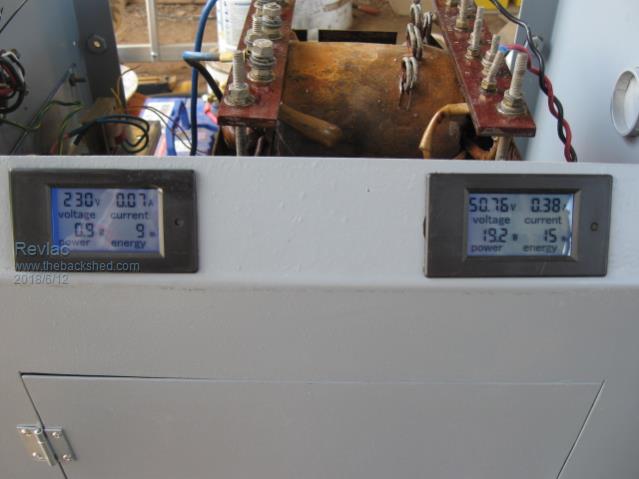 Checked the primary voltage, about 27vac and 230V on the secondary seems good enough to me, there is also a 12vac tap on the secondary which I might try later to see if that will replace the feedback transformer, and I don't think there would be any need to filter the output as it is part of the existing winding. The little choke that is hanging in there is not the quite correct will fix that later. 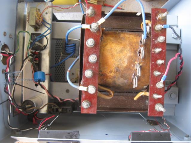 The ON/OFF switch was going to sit between the two power meters but then I decided to shorten the leads and place it inside were the rest of the switchers/circuit breakers are. 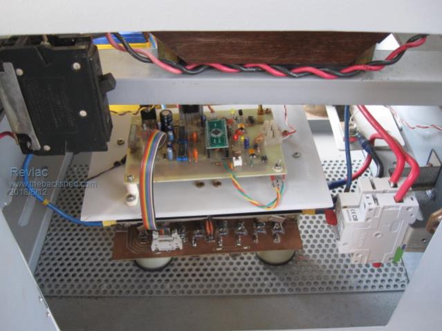 I still have to add the rest of the fets and the caps then give if a thrashing. 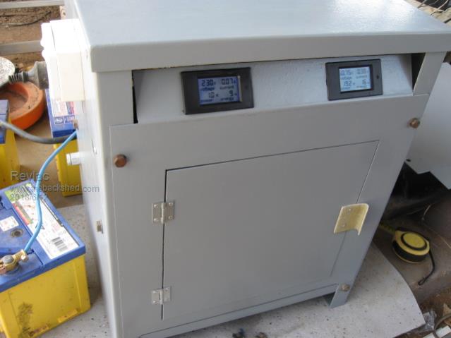 The case is the old SOLA computer regulator, Had that big ferroresonant transformer in it, turned into a pretty good inverter case I think. Cheers Aaron Off The Grid |
||||
| Madness Guru Joined: 08/10/2011 Location: AustraliaPosts: 2498 |
Looks really high-quality industrial in that case, how heavy is that transformer and what is the idle current with it? There are only 10 types of people in the world: those who understand binary, and those who don't. |
||||
