
|
|
Forum Index : Electronics : Another Inverter Build
| Author | Message | ||||
Revlac Guru Joined: 31/12/2016 Location: AustraliaPosts: 961 |
Hi Brian Both, very satisfying cuppa, well earned.  Cheers Aaron Off The Grid |
||||
| brucedownunder2 Guru Joined: 14/09/2005 Location: AustraliaPosts: 1548 |
Looks brilliant Aaron... I was looking at my un-used gear yesterday . Thought I might give the DIY inverter build a go ? Got the Bruce -wound torodial sitting there from the Powerstar W7 blow-ups thats a good start. Hope you and Dad have a good Xmas ,keep cool Bruce and Ilda Bushboy |
||||
| Warpspeed Guru Joined: 09/08/2007 Location: AustraliaPosts: 4406 |
Aaron, what sort of idling power are you measuring now, after tuning the transformer to 75Hz ? Cheers, �Tony. |
||||
| Revlac Guru Joined: 31/12/2016 Location: AustraliaPosts: 961 |
Merry Christmas, Bruce and Ilda A DIY Inverter will use up any spare time you may have, with your toroidal already done it is mostly the circuit boards and wiring. I have to say I enjoyed building this one.  Will be staying cool here. Just Got back late from a Christmas party.....  Tony Idle power is about 25w now after the tune up, it was a little less but adding the 16 extra fets consumed the 3 watts I gained after the frequency tune up. I reckon there is about 5w consumed between all the LCD meters, Still happy with that, it runs stable. Will try the other inverter again when I get some time. Cheers Aaron Off The Grid |
||||
| Revlac Guru Joined: 31/12/2016 Location: AustraliaPosts: 961 |
A friend dropped in this morning and left this Latronics 2.5Kw Grid Inverter, Not sure what he wants to do with it yet. 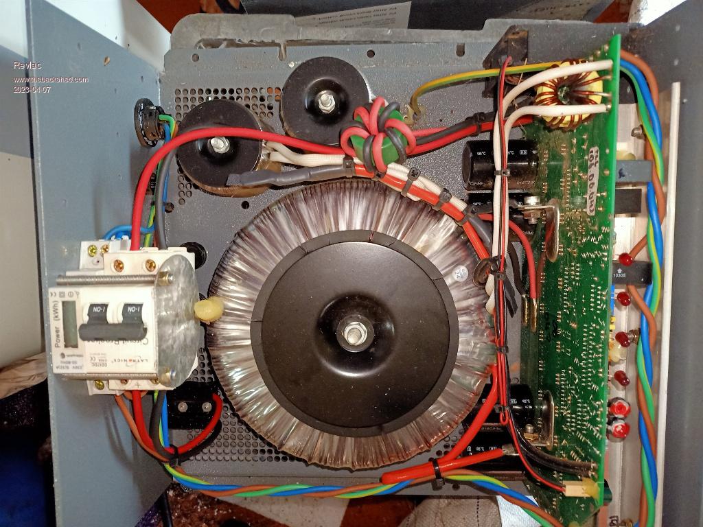 Had to have a look inside, looks like a good quality unit, It looks like the primary and secondary are wound together (not sure) anyone used these? Cheers Aaron Off The Grid |
||||
| Godoh Guru Joined: 26/09/2020 Location: AustraliaPosts: 379 |
I have a 2.3 kilowatt 24 volt Latronics inverter that runs our house. It has been very reliable and it runs very quiet. So pretty happy with it. My shed runs on an 8010 based inverter with a rewound powerjack (8kw) transformer, if powerjack say 8kw I take that to be the maximum it can run at for a very short time, so mine is thought of as a 2.5 kw max inverter. I am working on a new 8010 based inverter at the moment. I bought two transformers of Gumtree and have unwound them and glued them together. So the core is 190 mm outside, 90 mm inside and 100mm high. Realistically it should make another 2.5kw inverter when I get around to rewinding it. Pete |
||||
| Revlac Guru Joined: 31/12/2016 Location: AustraliaPosts: 961 |
Hi Pete, I heard good reports about the Latronics Off grid inverter's but they are very $$$$ especially around 5Kw. The bloke (He is 85 and doing well) dropped in, also left 5 other GTI's so opened them up to have a look inside, lots of goodies and those Aurora inverters have nice large chokes. Might build a picoverter one day, have fun with your build, it should work first time..... Cheers Aaron Off The Grid |
||||
| Godoh Guru Joined: 26/09/2020 Location: AustraliaPosts: 379 |
Hi Aaron, yep they are expensive the 2.3 kw 24 volt one was about $2400 new, I was really lucky and got mine for $1200 off gumtree. Unused, new in box. Sometimes luck just goes the right way. So far I have good runs with the 8010 chinese boards, I have two running one for my shed one for a separate hut. No problems at all. Previously I had powerjack inverters but they suffered badly from loose connections, bad joints in things and kept blowing up on inductive loads. So far no problems at all with the 8010 boards. The only problems are setting them up. Setting the current overload , under voltage and over voltage is a bit of luck and a fair wind. No paperwork with them doesn't help and the many different versions of the same design, make life much harder than it needs to be. Pete |
||||
| Revlac Guru Joined: 31/12/2016 Location: AustraliaPosts: 961 |
I guess this is the END of Latronics https://www.latronics.com.au/news/latronics-news-future-latronics I started my first build with the egs002 module, then on to the 8010 OZ Inverter style, sort of scratch built from page 1 on this thread, it still works last time I fired it up, I want to redo the choke for it, glad to see that we have come a long way since then.  Cheers Aaron Off The Grid |
||||
| Revlac Guru Joined: 31/12/2016 Location: AustraliaPosts: 961 |
Taken this latronics apart (as its no longer going to be used for its intended purpose) and the 2 chokes a connected in series, didn't see it properly when it was all zip tied together. Tested, 2 together was 1.689mH Taken apart they are 950uH and 1031uH I tested them several times with the elcheapo meter, numbers come fairly close each time, seen as these chokes where on a 60volt winding and unknown running frequency, they will be stripped apart and rewound as they are not even close to what we need for these inverter builds. On to something a little more interesting....or not....The auxiliary winding is about 20Vac and the Primary winding was 65Vac, (will need rewinding anyway). Did the usual 240v power test and The idel consumption is 10w, I was expecting about half that for a transformer of this size and quality, will need a few more turns wound on. Toroid measures 190mm wide. 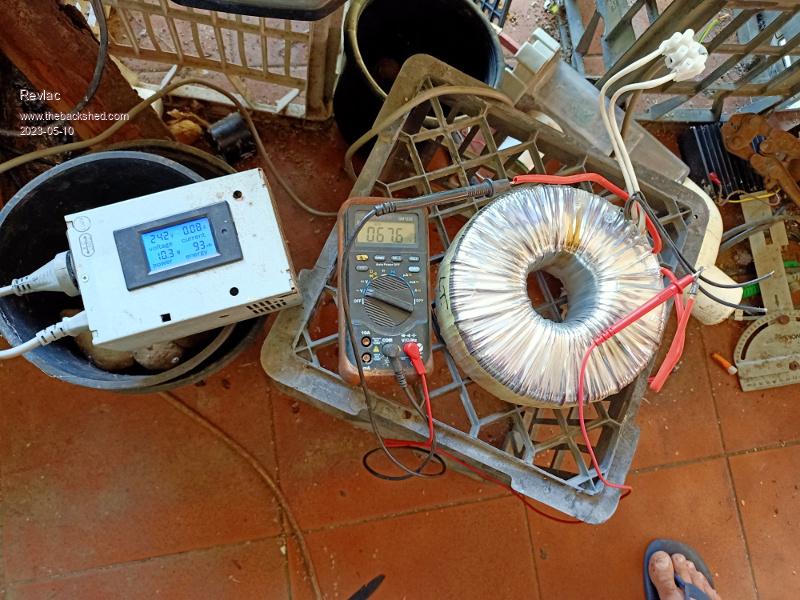 Cheers Aaron Off The Grid |
||||
| Revlac Guru Joined: 31/12/2016 Location: AustraliaPosts: 961 |
Haven't had much time to work on this, but made a start the other day unwrapping the plastic exposing the 65v primary winding, now the primary winding (RED covered wires) looked like 2 in hand and I thought, great this should take less time to to unwind.......well I was wrong,  it was 2 layers for each winding at 90 turns each wire. it was 2 layers for each winding at 90 turns each wire.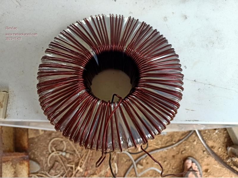 Just thought I would document this in case someone else tries, its good clean wire. 1 winding removed already, Once the other one comes off I will wind a few more turns onto the secondary 230v winding to lower the idle current a little more, depending on what sort of wire I find. Edited 2023-11-02 19:01 by Revlac Cheers Aaron Off The Grid |
||||
| Murphy's friend Guru Joined: 04/10/2019 Location: AustraliaPosts: 583 |
Ha, been there, done that . A tip: The two in hand machine wound windings had overlapped turns at the Latronics transformer I unwound.Problem with that is if the wrong 'hand' is being unwound first, one gets caught by the trapped wire and has to start unwinding the other 'hand'. Things can quickly get messy then  but it was good, re useable wire I got in the end. but it was good, re useable wire I got in the end. |
||||
| Revlac Guru Joined: 31/12/2016 Location: AustraliaPosts: 961 |
 And thats exactly what I did wrong ....Haha And thats exactly what I did wrong ....HahaCheers Aaron Off The Grid |
||||
| Revlac Guru Joined: 31/12/2016 Location: AustraliaPosts: 961 |
Made some progress, heatsinks made and drilled, still need to tap the threads but 4 are done already, all the board and heatsinks are mounted solid so nothing will get out shape. The toroid has a few more turns added and the Mylar tape wound back on, I saved all the tape and found it a bit crappy to use so I tried to straighten it out with the heatgun and it worked a treat, most of the crinkle come out, surprising how much heat it can take, it was nice and easy to handle after that treatment. Wound the Mylar tape back over the winding then went over all of it with the heatgun again and the Mylar tape settled in firm around the copper wire, works very well. Still need to wind the primary (have to find some first) on the Toroidal and dig up a few more choke cores, will be using the picoverter control board on this build, need to test this and another one to make sure everything is working. I have Programmed the nano for the low voltage cutoff and restart, this was still using the 51k (R17) resistor but the voltage was 2 or 3 volts out compared to the reading on the meter, will take another look at it later. 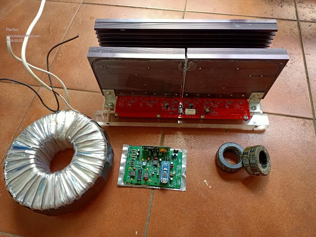 Cheers Aaron Off The Grid |
||||
| poida Guru Joined: 02/02/2017 Location: AustraliaPosts: 1389 |
the picoverter code does not have a menu for calibration. you need to sort it out in an iterative way. 1 - see displayed Volts. 2 - know what it should be. 3 - if displayed value is too high, multiply factor in code by (measured/displayed) else divide factor in code by same thing (measured/displayed) 4 - reprogram nano 5 - check again, so see displayed Volts. #define BV_SCALE 0.05986 // or something. Set it via trial and error. wronger than a phone book full of wrong phone numbers |
||||
| Revlac Guru Joined: 31/12/2016 Location: AustraliaPosts: 961 |
Thanks Pete, I thought it would be something like that, will try it tomorrow and program the other one as well. Footnote added 2024-02-06 15:21 by Revlac That line of code was in front me and I didn't see it, didn't have a screen connected so just trial and error with a voltmeter, #define BV_SCALE 0.0560 // or something. Set it via trial and error. ended up pretty near bang on. Cheers Aaron Off The Grid |
||||
| Revlac Guru Joined: 31/12/2016 Location: AustraliaPosts: 961 |
Getting closer to testing this one, mounted the control board, should be ok there, the wires are attached to the power board and not the heat sink this time. 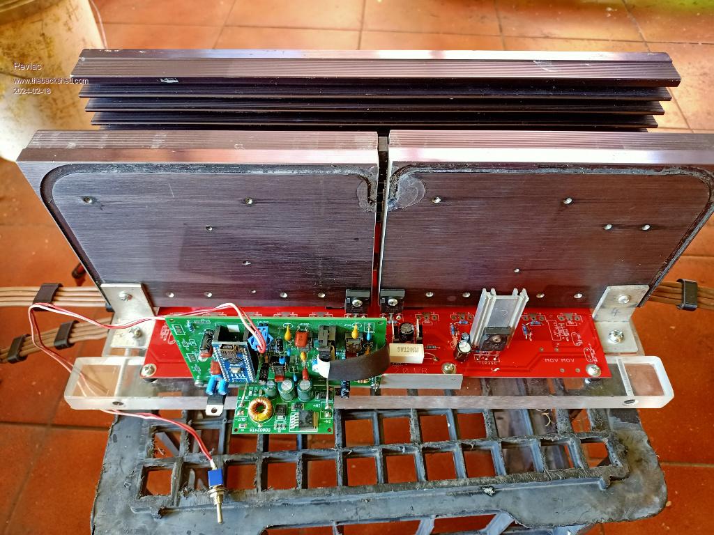 Using 4 wires could get a bit messy so thought I would try to tidy them up a bit and make them look flat using some 3D printed cable management, because I can. 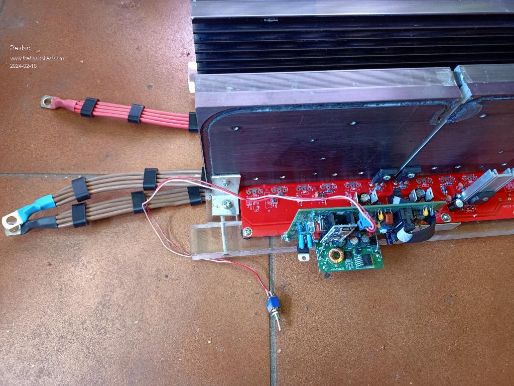 Cheers Aaron Off The Grid |
||||
| poida Guru Joined: 02/02/2017 Location: AustraliaPosts: 1389 |
that's looking good. wronger than a phone book full of wrong phone numbers |
||||
| Murphy's friend Guru Joined: 04/10/2019 Location: AustraliaPosts: 583 |
Hopefully you remember to sand off that black anodising where the mosfets mount. If I remember correctly that 3 heatsink design has the drain connection via the heatsink? |
||||
| Revlac Guru Joined: 31/12/2016 Location: AustraliaPosts: 961 |
Thanks. The wires are connected to the power board so the heatsink doesn't have to be live or wired, But Yes its definitely worth pointing that out so others can get it right. In my case I have drilled our the holes in the fets to 4mm and taped the heatsink accordingly, after attaching the fets I Checked the positive heatsink and centre leg of the fets with a meter and found there was no contact, because of a bur left from tapping the thread, after knocking it down with a countersink its all good. I might even put some sill pads or thermal paste behind the fets on this one as I don't need live heatsink's this time. Thinking about doing another power board with the Mosfets mounted underneath, will drill holes through the power board to hold the mosfets to a (insulated) aluminium block then attached to a massive single heatsink, just an idea, I haven't planed it through yet but it should work. Cheers Aaron Off The Grid |
||||
