
|
|
Forum Index : Electronics : Another Inverter Build
| Author | Message | ||||
Revlac Guru Joined: 31/12/2016 Location: AustraliaPosts: 961 |
 Yeah would be fun, they took them away though. Yeah would be fun, they took them away though.Cheers Aaron Off The Grid |
||||
| tinyt Guru Joined: 12/11/2017 Location: United StatesPosts: 431 |
Hi Aaron, I like that transformer, it could be an alternate configuration for us here with problems sourcing toroid cores. Also, I think winding it is much easier than a toroid. Is its core composed of two U-shaped cores? If two U-shapped cores, how were you able to minimize the air gap? Were you able to measure its idle power loss? Thanks |
||||
| Revlac Guru Joined: 31/12/2016 Location: AustraliaPosts: 961 |
Hi tinyt, Yes they are fairly easy to wind provided the winding direction is the same when it is assembled.(I wound both coils side by side the same way except the flat is on the opposite side) At least I think that's how I did it. A little bit of planning is required before winding the coils as well as the usual calculations, the start and end of the winding's must finish in the desired position on both sides (coils) and the flattened sides must end up facing each other when assembled. If any of it doesn't line up as planned, it would not be convenient to have the start and end winding at the front top and the other at the bottom back. Hope some of this makes sense.  It is two U shape cores. The air gap is minimal, the surface where the core meats, is lapped and polished. Idle power loss, will see how that turns out once I get it all together and running. Some details can be found here . They make a good transformer in a battery charger and I expect it to make reasonably good inverter if I have done it rite. I will follow up with more details later. Cheers Aaron Off The Grid |
||||
| BenandAmber Guru Joined: 16/02/2019 Location: United StatesPosts: 961 |
Please let me know to I've seen a few of these type Transformers on eBay here in the states The shipping is usually more than the Transformer which is a very good thing be warned i am good parrot but Dumber than a box of rocks |
||||
| Revlac Guru Joined: 31/12/2016 Location: AustraliaPosts: 961 |
Yeah It appears that they are rather hard to find on ebay or other searches, perhaps under different names. I think the best bet would be to look at (look inside) some power supplies that come on sale some times, or at some electrical recycle/scrapyard. Now a few months back I dug out an old Anti Shock Isolation transformer that was covered in dust, give it a good clean up, opened the cover to find a Nice looking C Core transformer inside, rated for 1kw 240v, have used it for the dishwasher and run 2.5Kw for upto 25min or so, through it no problem.  Just saying they could be hiding in places and hard to see unless you could take the cover off a power supply/transformer Box and see whats inside. Cheers Aaron Off The Grid |
||||
| Revlac Guru Joined: 31/12/2016 Location: AustraliaPosts: 961 |
Had a little spare time the other day, decided it was time to try winding the large choke, using just the material on hand. Started by using the 2 pair of laminated steel U Cores arranged as a double E, (similar dimensions to the large Aerosharps) only had some aluminum strap and some copper bar. The aluminum strap was 1mm thick and about 35mm wide, so 2 strips of this would fill the space nicely. The aluminium strap was only 3.1 meters long each, after it is (cleaned) folded around the copper bar and riveted nicely, it made up 13 turns for that size choke core, there is transformer paper between layers. Very important to make the former bigger. It Was a good learning process and will see if it works ok...or not.  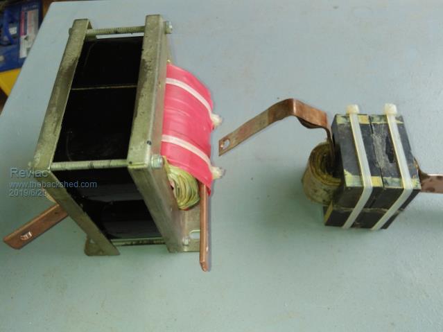 The little choke (on the right) is 2 pair of ferrite EE cores with 4 turns 2mm X 25mm copper strap, takes some effort to bend it. I used some hot glue to stick the cores together (not ideal) I can take it apart if its no good, Best thing is that it run's silent when I tested it last. More details soon. Fixed a mistake. Where's my coffee. Cheers Aaron Off The Grid |
||||
renewableMark Guru Joined: 09/12/2017 Location: AustraliaPosts: 1678 |
Type in electrical transformer, there are heaps in Oz, must be millions in the USA here here here here here here here Are they the type you were talking about? Cheers Caveman Mark Off grid eastern Melb |
||||
| Revlac Guru Joined: 31/12/2016 Location: AustraliaPosts: 961 |
Getting closer to firing this one up. After placing and mounting most of the components, to see if it all fits nicely, it was time to tear it all down for a paint job, (some of that silver paint that is actually grey). I have managed to fit most of the ugly wiring up the top, it is out of site and should not need any alteration once everything is working properly...hopefully. Also fitted up a push button to charge the caps through the pair of resistors, the voltage will be displayed on the volt meter and then switch the main breaker on when it looks good. 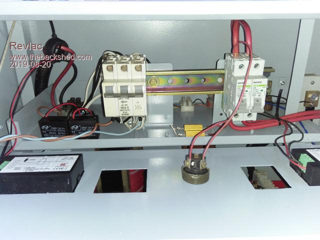 The rest of it is nice and opened and should provide good airflow around all the components, also I find it fairly easy get at any part if necessary. I am still learning about wire routing, trying to keep it neat but at the same time keeping signal wires apart avoiding potential noise issues that might (could, wood, will) cause problems. 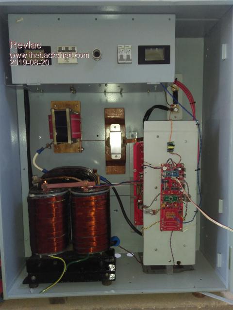 Still have to find some thermal grease for the temp sensors, and find the most appropriate spot on the transformer for the temp probe, I think placing it on the steal core just above winding's should be ok. 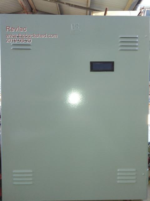 The front door will be fairly plain looking, only have one display with the info from the Arduino, it should be all I need most of the time. Hopefully get some time on the weekend to fire it up and see what happens, Will be running one fet per leg and no caps, to start off, if all is good I will put in the rest of the fets and try again. Will have to test another batch of fets, did this already some time back, but they have since been mixed up again. Also need to run an earth wire from the transformer, case etc. Slow progress. Cheers Aaron Off The Grid |
||||
| renewableMark Guru Joined: 09/12/2017 Location: AustraliaPosts: 1678 |
That has to be the neatest install I have seen. Makes mine look like a rats nest  Cheers Caveman Mark Off grid eastern Melb |
||||
Ralph2k6 Senior Member Joined: 24/09/2017 Location: AustraliaPosts: 129 |
Wow, giving Tinker a run for the 'most professional home-made inverter' award! - And you too Tony, classy work as always. Ralph |
||||
| Revlac Guru Joined: 31/12/2016 Location: AustraliaPosts: 961 |
Thanks guys. Its a bit of an improvement on my previous build, most of it is still made from junk/scavenged parts and not much planning was done. I wasn't in a hurry to get this one built, but I have really enjoyed the build process so far. I guess its on Me to make it work as good as it looks.  Haven't seen Tinker for a bit, hope all is well. Edit function still works. Edited 2019-08-22 21:23 by Revlac Cheers Aaron Off The Grid |
||||
| Revlac Guru Joined: 31/12/2016 Location: AustraliaPosts: 961 |
Ok fired it up and its runs, Have done some basic testing and found a few bugs. Firstly the idle current of 34w was a bit higher than it should be, given the results of my earlier testing of the transformer when I was testing the turn's vs Idle current. Checking my notes: Originally the 240v winding on this transformer was 246 turns I think? and the Idle current when tested (with 240v supply) was around 17w that would have been over 50w when run as an inverter. After rewinding to 380 turns for this 3120mm2 core the Idle current was about 7w, thats much better and run as an inverter that should work out just over 20w idel power. So 34w was wasted somewhere, going through the process of elimination I found that 8uf of filter caps was to munch, changed it to 4uf and tested again. Now running at 24w, much better, this includes all meters/electronics, could probably tune it a little more. Next issue was the temp sensor errors and the voltage readout was allover the place on the I2c display, will try some of those ferrite ring's and see if that settles it down a bit. The next issue is somewhat self inflicted. I connected the copper Earth shielding from the transformer to earth on the case, The inverter still runs ok but the nano and I2c module corrupted to buggery, a little red led on the nano started flashing rapidly. Removed the earth wire from the case and it run ok again, so I suspect the metal case on the I2c display is touching the metal door were it was sitting in the cutout causing interference, even though the negative does not connect to the metal case on the I2c display. Will have to figure out this grounding issue. So far nothing blown up YET... This little 5W AC-DC 12v Module has a bright red led on it, anyone else have this? 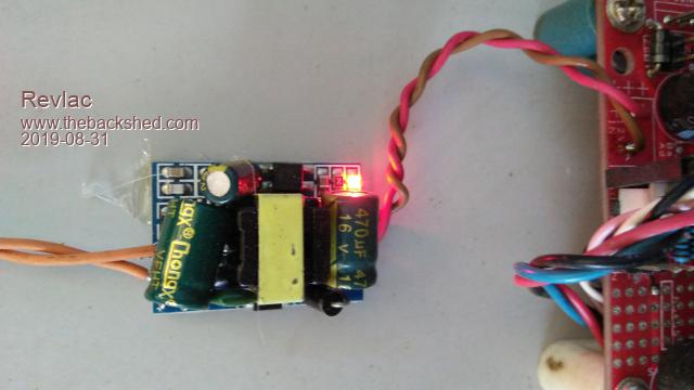 A bunch of these would make it look like a Christmas tree. Cheers Aaron Off The Grid |
||||
| Warpspeed Guru Joined: 09/08/2007 Location: AustraliaPosts: 4406 |
Measure the resonant frequency of the secondary winding plus capacitor, 75Hz is ideal. If its lower than 75Hz there can be problems with no load voltage being more than it should be. If its very much lower than 75Hz the idling power can be excessive. Different transformers can vary hugely in the amount of tuning capacitance required to hit the 75Hz sweet spot. Just did one for Mark, this was a mid sized toroid with (I think) about 300 turns which gave it a LOT of inductance. Only 2.5uF was required. Those little supplies all have that. Cheers, �Tony. |
||||
| Revlac Guru Joined: 31/12/2016 Location: AustraliaPosts: 961 |
Ok When this transformer was a battery charger it had 30uf caps and a rather large startup surge. Will have a go, I built a little signal generator, it might work ok for testing this. I was looking at the Chinese inverter boards some time back and they recommended 5uf? I think. I can see now that they had no way of knowing the many different transformer configurations that would be used. Will try to get it to 75Hz, see what happens. Cheers Aaron Off The Grid |
||||
| Revlac Guru Joined: 31/12/2016 Location: AustraliaPosts: 961 |
Did a little bit of testing today, trying to find the transformers resonant frequency. I setup the little frequency generator at 75Hz and connected it to the transformer secondary (with series resistor) then checked the voltage as is, 5.19v is the benchmark with no cap connected. 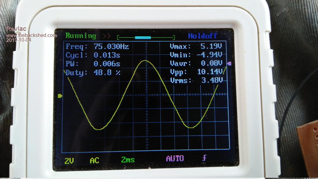 Connected the 4uf cap and the voltage drops to 3.89v 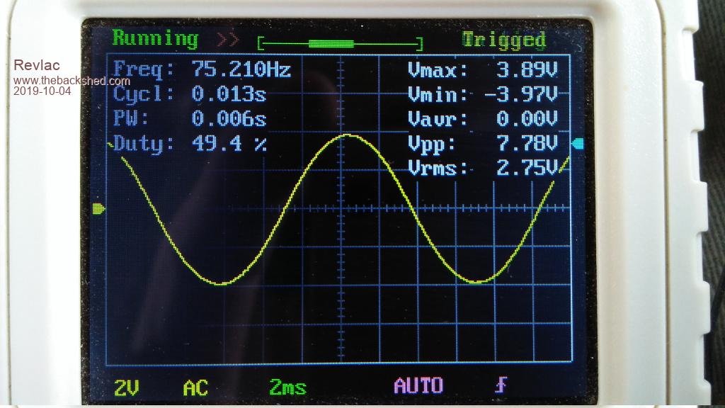 After several different cap values were tested, the highest peak I could achieve is 5.92v and that was using about 1.5uf capacitance, bit lower than I was expecting. 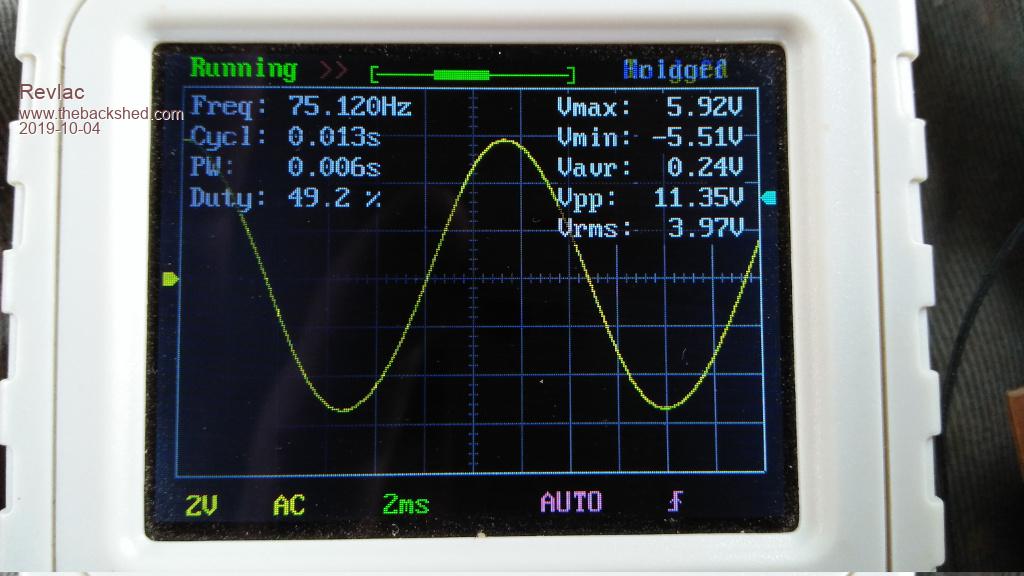 Just to get a better picture of what was happening I tried to find what the frequency was when running the 4uf cap, turns out to be 33hz, the 8uf I had. must have been something horrible. Not sure if I have done this correctly or not, but that's the result from using the gear that I cobbled together, using the LM324N and a few parts, its not ideal as the voltage changes with the frequency, easy just to set the frequency and then go through a selection of capacitors. Also checked the frequency with a meter so it is correct on the little DSO...Corrected using the vertical slider on the right. Hopefully this makes some sense. I will try this again on the other inverter just to see how far out it might be. Cheers Aaron Off The Grid |
||||
| renewableMark Guru Joined: 09/12/2017 Location: AustraliaPosts: 1678 |
Good work Rev. The way I remember Warp doing it, he set up a certain test cap on the secondary, then fed that secondary with the signal generator. The DSO was used to observe the wave and a rotary dial on the sig generator was turned to the left and right adjusting the hz output, to find a peak in the wave. As the hz output from the sig/gen is adjusted the wave changes shape to flatten out or get taller. At it's tallest point that is considered the tune for that cap. At that peak/tallest in the wave the hz was noted, if it wasn't 75, then more or less capacitance was adjusted. Test repeated till that peak in the wave was achieved at 75hz. I hope that was explained ok, Warp may need to clarify something. Cheers Caveman Mark Off grid eastern Melb |
||||
| Revlac Guru Joined: 31/12/2016 Location: AustraliaPosts: 961 |
Thanks Mark. Yeah. the explanation is plenty good enough. I just did it the other way round, set the signal gen to 75hz and went through a bunch of different caps until the I see the maximum peak in the wave. Anyway, either method works ok. Ok. tried this on the other inverter transformer (old EI type) and it was running with 5uf, turns out 6uf would be about right for it. I noticed when testing this one, first without any tuning cap connected, the signal from the transformer was triangle shape, just add any small cap and it changed to a proper wave shape. After getting the correct results with a 6uf cap, I tried to add a .22uf cap and the peak wave dropped noticeably, so it is really a very definitive peak. Its great when you can see what is going on instead of being in the dark taking a guess. Be a little while before I get everything together and running properly, place is dry as, I have to go get some water from a deep muddy pit down the back, before someone else finds it and pumps it out. Cheers Aaron Off The Grid |
||||
| Warpspeed Guru Joined: 09/08/2007 Location: AustraliaPosts: 4406 |
Great work there Aaron. A proper choke, and a bit of transformer tuning can make a surprising improvement to a whole lot of things. Cheers, �Tony. |
||||
| Revlac Guru Joined: 31/12/2016 Location: AustraliaPosts: 961 |
Definitely a good idea to do a tune up. During testing, with 20fets in place, it will use a few more watts idle power than the previous one fet per leg, I was expecting a little.... However I noticed a lot of heat generated on the control board at the 120r 5W resistor and the TIP35c transistor, after some checking, found I had a 13v volt zenor at the TIP35c on the power board. don't know how I missed it but anyway after fixing that the control board regulator etc. ran cool...now the heat has moved to the power board regulator but not so hot. I have tried a few different loads on the inverter and so far it is running quite well. Induction motors are good and the heater is no problem, large power tools with the soft start tend to give some minor little spikes on the waveform, but really nothing compared to what the little generator puts out. It has the best looking sine wave out of just about everything I have, just a little better than the HF inverter, Much better than my Friends inverter, a thing in a blue box. Dose not matter how good it is looking, everything still runs well, I was just wanted to get it without any wobble or blip at zero crossing. 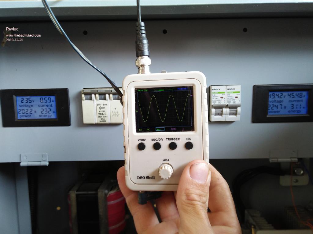 It is running a kettle here, this one was built for the shed powertools, starting things not so much long running loads. Still a few things I want to fix up a little, but its been a fun build....No fets were popped in this build yet. Cheers Aaron Off The Grid |
||||
Chopperp Guru Joined: 03/01/2018 Location: AustraliaPosts: 1032 |
Looks good Aron. No popped FETs; even better. Was running the kettle for a cuppa or just testing or both? Brian ChopperP |
||||
