
|
|
Forum Index : Microcontroller and PC projects : HC-12 Tester/Programmer PCB 1A...
| Page 1 of 3 |
|||||
| Author | Message | ||||
Grogster Admin Group Joined: 31/12/2012 Location: New ZealandPosts: 9981 |
As a follow-on from my other HC-12 thread, here is what I have so far for the programmer/tester. 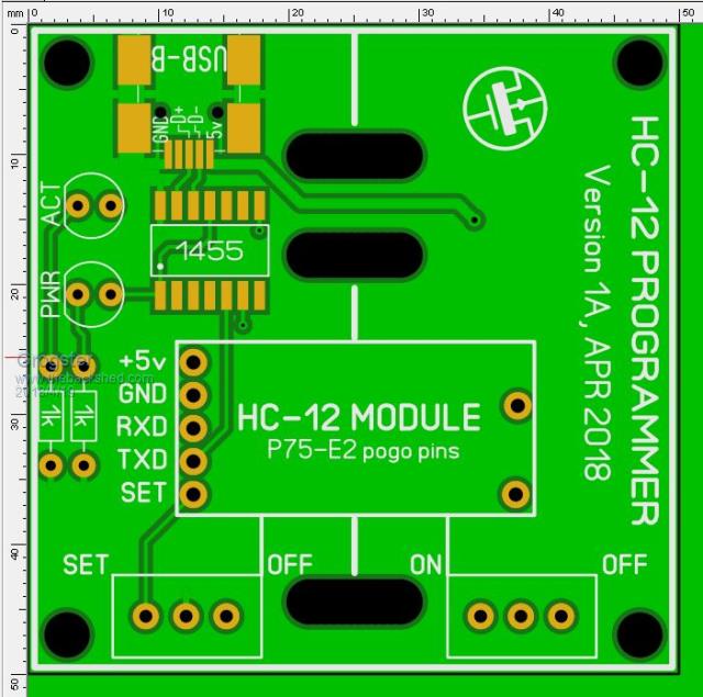 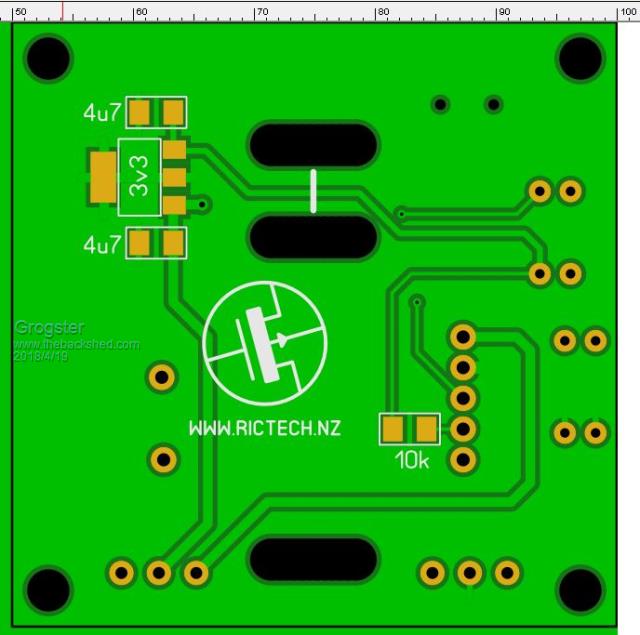 The board is 50mm square, and incorporates a 1455 USB interface for the serial. As this board is HC-12 specific, I have not bothered with the ICSP pins or the SELECT tact, as all I wanted was just a plain old USB-serial adaptor on-board so I did not have to hunt around for one to plug into it. Two mini slide switches control the unit, with one being connected to the HC-12's SET line to easily allow you to hop in and out of setup mode. The other slide switch turns the power off and on to the HC-12 module. The two slots above the module, and one below, allow for module restraint by way of a wide rubber-band, that you cut so it is one long length of rubber strip. The end by the switches is fixed, and the other end is threaded through the upper two slots, so you can easily loosen it, insert a module to test or program, and pull the rubber-band though the two upper slots, which will pull the module down on the pogo pins. The rubber will grab on the edges of the slotted holes, holding it in place for the duration of the testing or programming. That's the idea, anyway. Rubber is a conductor of static electricity, so I will have to test this idea a bit more, but I don't see there being THAT much friction to charge up the rubber band, but perhaps elastic would be better.  As well as allowing you to easily program an HC-12 module WITHOUT soldering any pin-strips to it etc, it will also allow you to send it test data that it will transmit which can quickly and easily be checked for frequency with the likes of a UHF scanner radio. Here is the scanner radio I use - US$35. The pogo pins are P75-E2 type, and 100 of them can be had for US$2. Having a conical head, these ones self-centre in the holes on the module, and it also makes for quick alignment of the module on the pins, as they 'Want to be together' - isn't that sweet....  Smoke makes things work. When the smoke gets out, it stops! |
||||
| kg4pid Regular Member Joined: 08/03/2015 Location: United StatesPosts: 50 |
Maybe I missed it, but does this board have a place for an antenna or are you going to use an external antenna? |
||||
| Grogster Admin Group Joined: 31/12/2012 Location: New ZealandPosts: 9981 |
For the purposes of testing, you usually don't need an antenna.  You could put an external one on the U.FL socket if you needed to use it to range-test, but that is not really the purpose of the board. Having said that, it would be a good idea to have a hole in the PCB so you can put a simple wire on if you want. Thanks for the tip.  Smoke makes things work. When the smoke gets out, it stops! |
||||
| Grogster Admin Group Joined: 31/12/2012 Location: New ZealandPosts: 9981 |
Here is a photo of a completed unit: 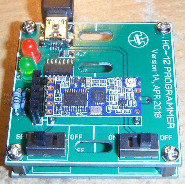 The rubber-band idea was a failure.   The pogo-pins have enough force collectively, to pull the rubber-band back through the slots. Oh well - was worth a try. For now, I am just holding the HC-12 on the pins - that works, but means you lose one hand, so I am working on some other method. Because there are five pogo pins at one end, but only two at the other, you need more force at the connections end then the antenna end - should have seen that before - oh well....... The board works fine to read, program and test the modules though. I just need to think of a more suitable module restraint system. Smoke makes things work. When the smoke gets out, it stops! |
||||
Azure Guru Joined: 09/11/2017 Location: AustraliaPosts: 446 |
A little swing lever made of plastic with a hole at one end and a slot at the other. Swing it away to change modules, swing it in over a module push it down (against the pogo pins) and into a retaining screw which has a washer on top for the slotted end to go under. Both screws raised up from the pcb with nylon spacers. I you used washers (maybe need nylon ones gainst PCB) you might be able to use the rubber band slots for the screw holes. You could use a nylock nut to keep the screws at a set tension and a little spring (above the lever pushing down on it using a longer screw) if you want more pressure. If that makes sense. That's what I was thinking of doing (when I read the rubber band idea , that is when I eventually get one. |
||||
plover Guru Joined: 18/04/2013 Location: AustraliaPosts: 306 |
I do love that testing arrangement (and I do not have an HC-12) Can't help to suggest sort of springy piece of say hardened fence wire using the two nice slots. Flat piece of spring from an old wind up alarm clock, I seem to remember I have such in my scrap bin. 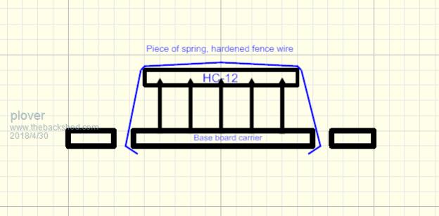 May well require a bit of insulation. Hmmm piece of single strand copper mains wiring. Board kit available in the shop? |
||||
| Andrew_G Guru Joined: 18/10/2016 Location: AustraliaPosts: 883 |
Hi Grogs. Is it not possible to put a flatish weight (insulated of course) in the "sweet spot" on the module? Given that there are pads to which the coil antenna can be attached is it possible to re-design or modify the PCB so a pogo pin, with an antenna attached, connects to one of these? Cheers, Andrew |
||||
| CaptainBoing Guru Joined: 07/09/2016 Location: United KingdomPosts: 2171 |
how about a pogo pin with a 86mm (1/8th wave) "squiggle" on the PCB? |
||||
| Grogster Admin Group Joined: 31/12/2012 Location: New ZealandPosts: 9981 |
@ Azure - I think I see what you are getting at. I will have a play with the idea. @ plover - Not available on the website. I can put it up there if anyone is interested. @ Andrew_G - I like the weight idea - I will look into that. That might be all we need. The board caters for an external wire or helical antenna - there is a pogo-pin in place for that: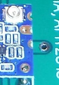 EDIT: Here is another shot of the board without HC-12 module: 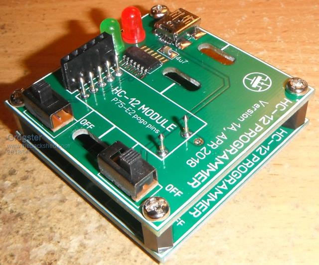 There is a pogo-pin for the antenna connection, coming out to a PCB-based coplanar wave-guide set for 49.93-Ohms, which was as close as I could get to 50-ohms. Smoke makes things work. When the smoke gets out, it stops! |
||||
| MicroBlocks Guru Joined: 12/05/2012 Location: ThailandPosts: 2209 |
If you have one of these: 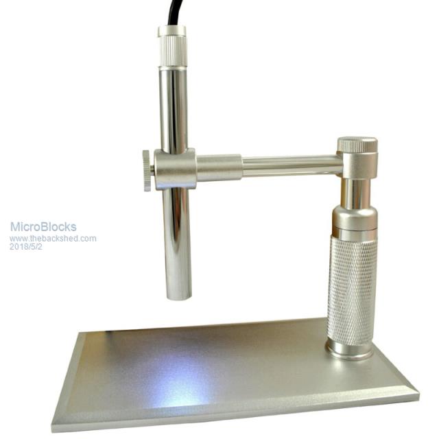 You could remove the microscope and replace it with a pencil or mabe a dowel and use it as a clamp. :) Microblocks. Build with logic. |
||||
| Grogster Admin Group Joined: 31/12/2012 Location: New ZealandPosts: 9981 |
I don't, but all ideas are ideas! Thanks. Smoke makes things work. When the smoke gets out, it stops! |
||||
| Andrew_G Guru Joined: 18/10/2016 Location: AustraliaPosts: 883 |
Hi Grogs, I hadn't appreciated that there IS a connection for an antenna on the PCB. With that I suggest all you need now is one of these: 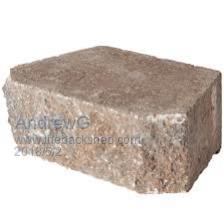 Cheers, Andrew |
||||
| robert.rozee Guru Joined: 31/12/2012 Location: New ZealandPosts: 2537 |
search for TOGGLE CLAMP on ebay, like this one for example: https://www.ebay.com/itm/253323279398 these are generally what are used on professional programming and test fixtures to hold parts in place during testing. cheers, rob :-) |
||||
| Grogster Admin Group Joined: 31/12/2012 Location: New ZealandPosts: 9981 |
Wow, Rob, yes, those look like just the ticket. All about knowing what they call a thing. I had never heard of those before, so this is news to me. Will study these in more detail.For now, I might steal Andy's rock idea - I have plenty of those about the place.  Smoke makes things work. When the smoke gets out, it stops! |
||||
| Azure Guru Joined: 09/11/2017 Location: AustraliaPosts: 446 |
@Robert I have a bunch of those (woodturning and cabinet making jigs) but I did not think to suggest them as even the small ones are a little big for what is needed. Grogster might like them, they are very handy if setup properly. Edit: Grogster you managed to hit reply before I sent my reply. I think you should use heavy rocks, solid gold nuggets covered in an insulator might work well  |
||||
bigmik Guru Joined: 20/06/2011 Location: AustraliaPosts: 2981 |
G�day grogster, Have you thought of trying a couple of those strong magnets? Glue one to the test pcb and use an insulated one on top of the HC12. Just a thought. Regards, Mick Mick's uMite Stuff can be found >>> HERE (Kindly hosted by Dontronics) <<< |
||||
| Bill7300 Senior Member Joined: 05/08/2014 Location: AustraliaPosts: 159 |
From memory, they are known as over-centre toggles to the mechanical engineer.A very handy concept. Bill |
||||
| Grogster Admin Group Joined: 31/12/2012 Location: New ZealandPosts: 9981 |
@ Mick - another clever idea! Thanks. Smoke makes things work. When the smoke gets out, it stops! |
||||
Quazee137 Guru Joined: 07/08/2016 Location: United StatesPosts: 603 |
I don't have a 3D printer but I sure some one here does. I borrowed plover's image. 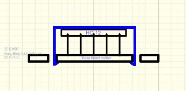 It's inline with a reflow oven.  |
||||
| Azure Guru Joined: 09/11/2017 Location: AustraliaPosts: 446 |
@Quazee137 Now that's a clever solution a nice custom printed plastic clip. It is the ability to make little things like that that make me want to get a 3D printer. Alas I have not gone down that path yet. |
||||
| Page 1 of 3 |
|||||
| The Back Shed's forum code is written, and hosted, in Australia. | © JAQ Software 2026 |
