
|
|
Forum Index : Windmills : Few starting out questions
| Author | Message | ||||
| BarkyJ Senior Member Joined: 26/04/2018 Location: New ZealandPosts: 114 |
So stoked. Got myself a big as storm water pipe to make my propellers out of. Its about 630mm diameter with 18mm thick walls and 1.5m long. FREE :) |
||||
| flc1 Senior Member Joined: 20/11/2011 Location: New ZealandPosts: 242 |
Cool, sounds like your sorted, have a yarn with fillm about some blades, they will give you so much more power . |
||||
| BarkyJ Senior Member Joined: 26/04/2018 Location: New ZealandPosts: 114 |
 |
||||
| BarkyJ Senior Member Joined: 26/04/2018 Location: New ZealandPosts: 114 |
Yes I have seen his stuff http://www.ozwindengineering.com/Products.php Really good, and something I will aim to use in time, but now I am trying to prove a concept on the cheap, but trying to do it as right at possible for a first timer, at the same time. Want to give this a go, and see what happens, and if it works then I can look at upgrading/changing as time goes on. I just want to prove the concept first without spending a lot of coin (which I don't have spare at the moment). I have a 3 phase rectifyer the same as is on that page, already on its way. The slip rings are neat that are on that page, and something I will look at if required down the track, and yes the blades are ideal obviously. |
||||
| BarkyJ Senior Member Joined: 26/04/2018 Location: New ZealandPosts: 114 |
@DaveP68 The part number of the Black rotors, is that 438503P? or is it something else? That is the number I got off the F&P website, however I do not see that marking on the Black rotor I have here.    Thanks |
||||
| flc1 Senior Member Joined: 20/11/2011 Location: New ZealandPosts: 242 |
Thats the correct black cap |
||||
DaveP68 Senior Member Joined: 25/11/2014 Location: New ZealandPosts: 292 |
Hi BarkyJ Yes as Fred stated, that's the correct black cap. There are realities if you do not accept, will lead to frustration because you will be spending time on wrong assumptions and the results cannot follow! The Dunning Kruger Effect :) |
||||
yahoo2 Guru Joined: 05/04/2011 Location: AustraliaPosts: 1166 |
there are a few things that are complete dealbreakers with turbines. if you mess these things up it will wear you down mentally. tower blades bearings A tower that doesn't position the turbine above the turbulent air on a warm day is pretty powerless. A tower that cant be lowered easily for regular maintenance is a complete liability. Blades that have high strength and high aerodynamic lift are a miracle in motion and worth every cent you pay or minute you spend building. and they are quiet! poor blades are either not turning at all or one full rotation away from exploding shrapnel. Dont even think about running tapered roller bearings on a stub axle, they are not designed to be run without constant preload and will rapidly fail. Use tiny amounts of the best grease you can afford, I use Moreys waterproof grease. everything else is fun, negotiable and tinker-worthy I'm confused, no wait... maybe I'm not... |
||||
| BarkyJ Senior Member Joined: 26/04/2018 Location: New ZealandPosts: 114 |
Thanks Yahoo2 No issues with the Tower, have some ideas for that already. Blades - while I would love to pay for the right blades right away, investing in something I dont even know if I will end up using long term, or if the property is suited - I will just continue down the path I am on now and make educated guesses based on knowledge from on here and other systems I have seen, and just see where I get. Yes I would love to just buy everything right, but thats not really in my nature. Failure is just a part of learning. Regarding the bearings - what are the suggested bearings to be used? Just standard sealed 6005-2RS's or something else? This I have not got to yet, as I am not up to that stage. But good to know. I am designing everything I do in CAD, even the blades I am doing in CAD based on the 18mm wall pipe I have, and adjusting the angle of cut on them to see the different profiles I get out of a blade. I have a good friend who was an aircraft mechanic for many years, and he is suggesting I am going on the right track, so I will persevere. If it doesnt work, then I will just try something else. End of the day, its just time wasted, materials for these things have so far been free or cheap. I do appreciate all input though. I just don't want to go down the track of buying everything, I would prefer to give it a go myself and see how far I get. |
||||
| BarkyJ Senior Member Joined: 26/04/2018 Location: New ZealandPosts: 114 |
Can anyone see any issues with this - a response would be appreciated. If I have a dual stator windmill, set up to output 24V or 36V in currently unknown configurations yet. If I put that through a 3 phase rectifier (or multiple) and then join the DC lines together, through a suitably sized MOSFET which gets PWM'ed based on wind speed, directly into a immersed DC water element in a hot water cyclinder. I have found a dual AC/DC element. 2x coils rated 36VDC 450W each, 3ohms. 1x coil rated 240VDC 2KW, 30 ohms. If I take the DC coils, put them in parallel, I get 1.5ohms. For a 900W element, if generating say 30V, I should be able to push 20A into the 1.5ohm load, which would be about 600W. Adjusting the PWM to adjust the load, should then adjust the voltage, of which I could go up to 36V. So its essentially a dump load of 900W capability into water. Does anyone see a problem with this? This is just to test out the windmill itself, before I take the next step and do batteries and electroncs and dummy loads and all that - which I am still not sure if I will need or not, as this element likely will be the main load. Would love to hear from someone. Found the Element for $70 locally... |
||||
| BarkyJ Senior Member Joined: 26/04/2018 Location: New ZealandPosts: 114 |
Another question I have is about the wiring of the stator, and how RPM translates into voltage/current etc. This I havent got my head around yet. I have seen the table: 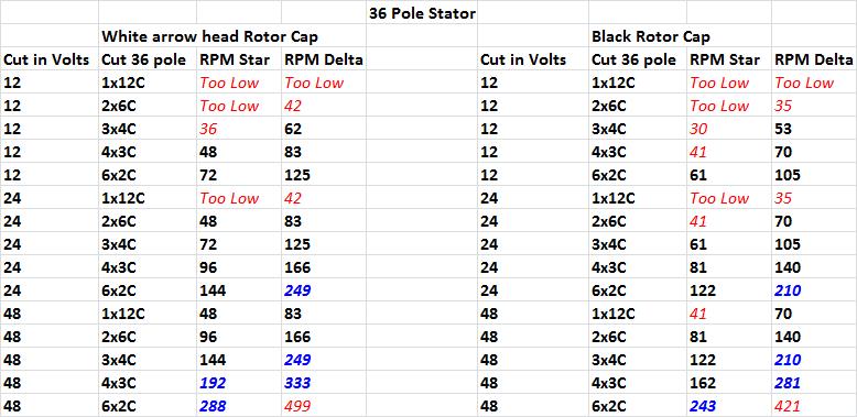 Unsure if 36V is an OK voltage to aim for or not, if if its a bit weird, and I should be aiming for 48V. Looking at the table, it is not clear to me what 'Cut in Volt' actually means. Does it mean that if I had a 4x3C 36 pole single stator with black rotor configuration, that when the rotor is spinning at 81RPM, I should be getting about 24V out? Or does it mean something else. Basically as per my last post, if I have a 900W element 1.5ohm rated to 36VDC, how exactly do you regulate the voltage that comes out of the windmill - is it purely by the load put on the stator from the controller? I assume if it had no load connected, it would just spin faster and faster and the voltage would rise until the point it was free spinning and not doing anything other than tearing itself apart? But if you then apply a load to it, the speed will drop. Its then a case of adjusting the load, to maintain the best voltage you want to see, and you basically get the current which matches that based on the voltage and the wind strength? so if I was PWM'ing my FET which adjusted the average load that the stator sees, then this should vary the load, which should regulate the speed, right? But how do you figure out a starting point, to know at this RPM I should expect to see this voltage? Is that where the table comes in, and was my assumption right about that? 81RPM on a 2x3C 36 pole stator with Black rotor, I should expect to see around 24V? Where is the limit exactly, at what RPM do these stators stop working right? How do you determine the max potential the system has? Sorry for all the newbie type questions, having never touched one of these, and scouring posts and articles all over this site to pull together information, it is a little tricky to figure out. Hopefully someone can help get some sense into my head. Thanks |
||||
| flc1 Senior Member Joined: 20/11/2011 Location: New ZealandPosts: 242 |
Hi Barkyj Cutin volts means the voltage that your inverter or charge controller starts to use the electricity(take current),, so if you have a controller or inverter that is set for a startup of 45 volts then when it sees 45 volts it will start useing that power and it will put a small load on your turbine ,as the voltage increases it will pull more current (amps) and put more load on and so on . Yes ,,no load on your turbine means just that...no load, so its free wheeling its way to destruction lol. I think from memory you will get(unloaded) 1 volt per rpm from a standered uncut 36pole copper stator with black cap, and if you cut the stator electriclaly in half (2x6 coils) then you will get about half a volt per rpm, and with a third cut stator (3x4Coils) you will get about one third of a volt per rpm. I reckon if you aim for a cutin rpm of between about 75-95 rpm you should be ok,there is usualy a bit of useful inertia in the blades by then. If you wire the stator in Delta you will get about 40% drop in voltage per rpm,but about the same % increase in current per rpm, and same with the previous stator cuts I mentioned you should get increase in amps relivant to what ever cut you have,,,,,so if you half the voltage ,,you double the amps, or current. Once a load comes on you should see about 40% drop in voltage. there are good charge controllers and solid state relays etc on aliexpress that are not too exspensive that you could use for what you want to do, I know you want to do it all yourself, but spending a bit of money on the right things can save you alot of stress and sweat. I think somebody will correct me if Im wrong ,in regards to your tower electricity travels more efficiently over distance if it is in AC form. |
||||
| BarkyJ Senior Member Joined: 26/04/2018 Location: New ZealandPosts: 114 |
Thanks Fred Good - So that all makes sense. I have seen some charge controllers etc on Aliexpress yes, but I havent ventured too deep there yet. Because I dont want to use batteries to start with, and the Chinese explanations are not always too clear, its hard to know if they work direct with a load without batteries or not. Thats why I thought I would throw some bits I have together and make a controller myself, to start with at least. Regarding stress and sweat, unsure if buying a Chinese controller will alleviate that or not, hah. But yes, I get what you mean, but I think I can do a pretty decent job at least to get something up and running. Cable wise, AC or DC over a distance, is a good question. I know higher voltage (lower current) travels better than lower voltage (higher current), but unsure about AC vs DC. Tradeoff is then, 3 wires vs 2 wires, as the 3 wires of AC only save you maybe 1 or possible 2 AWG sizes, depending on length, so hmm. 10mm2 wire seems to be required to go 20m (40m round trip) - so there is $200 for the cable. If I need to go further, then its 16mm2 I guess. How far did you have to travel with yours Fred? Here is the same element as what I got coming. https://www.trademe.co.nz/building-renovation/heating-cooling/heating-systems/auction-1626041473.htm 1x 60ohm 240V 2kW, and 2x 3ohm 36V 450W (Parallel for 900W 1.5ohm) Cheers |
||||
| flc1 Senior Member Joined: 20/11/2011 Location: New ZealandPosts: 242 |
my cable run was only about 15 meters to the inverter, yep high voltage more efficient. |
||||
| DaveP68 Senior Member Joined: 25/11/2014 Location: New ZealandPosts: 292 |
Hi BarkyJ One extra point of note, the working output voltage of an F&P stator must rise in proportion to RPM and the current needs to increase at a rate of 2x RPM. This is also known as Maximum Power Point Tracking. This is the most efficient way to extract electrical energy out of any wind turbine. Deviate from his rule on a wind turbine and you will drop the system efficiency dramatically. I.e. charging batteries directly from the output of the rectifier is an example of how to drop your system efficiency. I have a working PWM circuit using MPPT, that can feed into a resistor of as low as a few ohms and happily operate up to 1 kW or more. The switching elements are IGBT's and it can start operating at a voltage of say 30 VDC cut in. Or be modified for high voltage application up to 500 VDC. My current unit has only been tested up to 7 Amps DC at 950 W. The MPPT part is a table programmed into memory that is pre-calculated. Fred is correct in saying it's best to run a higher voltage system. The conductor size of the wire down the tower can be much smaller and system efficiency will be better overall. Also all the electronics including rectifiers can be located at a longer distance when using a higher voltage AC 3 phase. There are realities if you do not accept, will lead to frustration because you will be spending time on wrong assumptions and the results cannot follow! The Dunning Kruger Effect :) |
||||
| BarkyJ Senior Member Joined: 26/04/2018 Location: New ZealandPosts: 114 |
Thanks Guys Dave what IGBT's did you use? I have some of these: IRFB3006 and some of these: HUF75339P3 If they cut in at the right time and never experience voltages over their limit, then they might be OK, but if voltage ramped up and got out of hand, then I would imagine they would pop. So in my situation where I have a 36VDC Load capable of 900W, measuring 1.5ohm, what system voltage should I be aiming for? 48V? Higher? Thanks |
||||
| yahoo2 Guru Joined: 05/04/2011 Location: AustraliaPosts: 1166 |
there is a basic formula/ principal I am having a hard time remembering ATM, I just got distracted by Janice Peterson's white dress. if you ignore the 3 phase to DC rectified difference in voltage for a moment, and the resistance in the wire and the potential of MPPT. You can adjust for that later. Ummm, so the load determines the voltage. 24 volt battery will start at around 26-27volts and finish at 29.6 volts your wind turbine will output a voltage per rpm based on the resistance of the coils. here is the tricky bit. No , its no good, Janice is doing it again! Here is the answer I gave someone several years ago. unfortunately the website with the formula doesn't exist anymore. I might have a copy I can post if I can find it. I'm confused, no wait... maybe I'm not... |
||||
| BarkyJ Senior Member Joined: 26/04/2018 Location: New ZealandPosts: 114 |
Thanks Yahoo2 Cracking up reading your comments about Janice - I had to google to figure out who she was. :) That explains alot, thanks for your post. I guess in normal applications, people are charging batteries or directly into gridtie inverters etc. I do want to get into that, but to start with I just want to dump everything I can, into the element. This will then give me time to figure out the conditions here, and just understand the windmill itself, without the distraction of batteries etc. So in terms of wiring configurations for the stator, if I aim for low to mid wind only (we wouldnt see high wind often, and when we did I would likely shut this thing down). If I use a 36Pole 2X6C configuration, and aim for max power into a 36V load, I wonder if that is the best idea. So because I dont have to overcome battery voltages, nor worry about over charging etc, I just have to ensure I am only putting 900W max in when at 36V. So based on previous tables, potentially at around 60RPM I would see 36V coming in. I then just adjust the load based on the voltage, and try and keep it around the 36V mark. Does that sound viable? Do you guys use any sort of RPM sensor? I know the stators have a sensor on them, but I haven't yet looked at what sort of output they give. It would be quite neat to record this and even use it in the calculations. Anyone played with the build on sensors at all? I have a vague recollection they are 3 bit and increment in some sort binary pattern, so even using 1 bit just to get a blip on rotation, likely will suffice... |
||||
| DaveP68 Senior Member Joined: 25/11/2014 Location: New ZealandPosts: 292 |
Yes had to look up Janice too, I got got distracted...  The IGBT I used is a 600 VDC version with lower current limit IRGBC30S It can still be use to drive a resistive load of about 20 - 30 ohms if used in the high voltage low current mode. To use the 1.5 ohm heating element will require a lower voltage higher current device. For an RPM sensor just reuse the RPS unit that was mounted on the 36 pole copper stator. 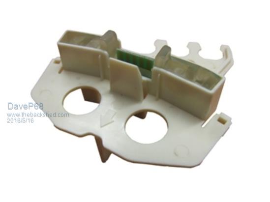 Has 5x pins +15 VDC, 0 VDC, phases 1, 2 & 3 outputs. Only need to use a single phase output to measure RPM. 24 pulses per/sec = 60 RPM. David There are realities if you do not accept, will lead to frustration because you will be spending time on wrong assumptions and the results cannot follow! The Dunning Kruger Effect :) |
||||
| BarkyJ Senior Member Joined: 26/04/2018 Location: New ZealandPosts: 114 |
Thanks Dave So 15VDC for those RPM sensors, is that the limit, or thats the nominal voltage? Can it run from 5VDC? 24 pulses per/sec = 60RPM, is that for a stock stator, and does it change when you change the stator wiring, or totally independent of that? where does 24 pulses per second come from exactly? 60 RPM = 1 RPS so 1 rotation is 24 pulses... ? But arent there 36 coils, split into 3 phases, so wouldnt you get a 12 pulses on each phase output of the sensor, each rev? How do you get 24? Sorry I have no idea how these work, just trying to get my head around it. Thanks :) |
||||
