
|
|
Forum Index : Windmills : Few starting out questions
| Author | Message | ||||
DaveP68 Senior Member Joined: 25/11/2014 Location: New ZealandPosts: 292 |
I have no problem with your questions, as you're still new at this. The 24 pulses translates to 24 Hz, which intern refers to the black rotor cap having 48 magnets (24 North poles + 24 South poles). So 1 rotation per/sec produces 24 pluses out of each Hall effect sensor. The 15 VDC supply will be their upper operating limit and they will still work down as low as 10 VDC. When using a 42 pole stator with a 56 magnet rotor cap the output of the RPS (it uses a different version) will be 28 pulses (28 Hz) for 1 rotation per/sec. In the past I used a Fluke multimeter in frequency mode to measure RPM. Now I use a Fisher and Paykel motor controller board with only the RPS unit connected (motor disconnected) to show RPM. When in diagnostic mode it can give you the true RPM reading. These F&P motor controllers aren't isolated so all connections in & out of the board are considered at mains (230 VAC) potential!! 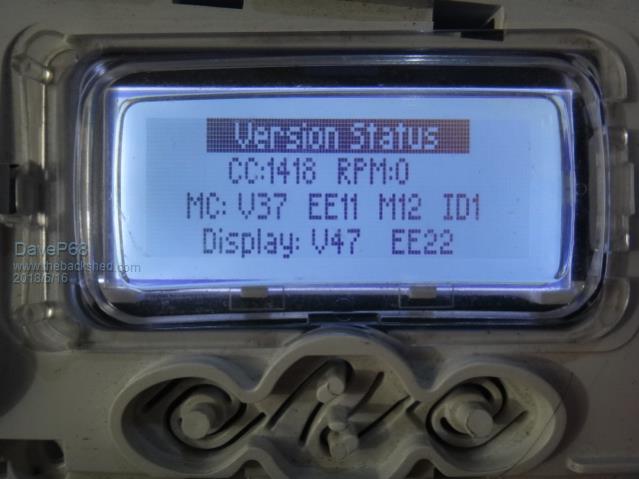 Here's a display module connected to a motor controller I use to measure RPM. There are realities if you do not accept, will lead to frustration because you will be spending time on wrong assumptions and the results cannot follow! The Dunning Kruger Effect :) |
||||
| BarkyJ Senior Member Joined: 26/04/2018 Location: New ZealandPosts: 114 |
Awesome thanks Dave ok 24 pulses it is then. I hope to set up a bench test using an old drum to start with, and a drill, and start putting together some sort of basic controller with LCD readout, and have it vary a load and just see how it reacts. Thanks again |
||||
| BarkyJ Senior Member Joined: 26/04/2018 Location: New ZealandPosts: 114 |
I think the best FET for me to use is the IRF3006 which is 60V 195A rated, and logic level compatible so simple to control, so at 5V its fully on and capable of switching the full current. Sad the RPM sensor doesnt work down at at 5V, but thats alright, ill make it work or even put on a different RPM sensor entirely. |
||||
| DaveP68 Senior Member Joined: 25/11/2014 Location: New ZealandPosts: 292 |
Hi BarkyJ Have you checked out my topic on F&P Electronic Dynamic braking ? The circuit that is published lower down on page 2 can be modified to operate in a dual mode that controls both the voltage and current to achieve MPPT. Also the IGBT can be substituted for a IRF3006 and simpler to control like you say. David There are realities if you do not accept, will lead to frustration because you will be spending time on wrong assumptions and the results cannot follow! The Dunning Kruger Effect :) |
||||
| BarkyJ Senior Member Joined: 26/04/2018 Location: New ZealandPosts: 114 |
Hi David I had seen that circuit when I was reading as many posts as I could. Isnt it something for your dynamic breaking, rather than voltage current control? You are talking about this Dynamic Breaking concept circuit, right? 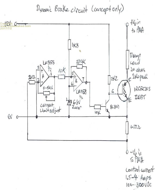 You are doing pure hardware control are you, rather than software controlled hardware? |
||||
| BarkyJ Senior Member Joined: 26/04/2018 Location: New ZealandPosts: 114 |
Popped back to the trusty Dump shop again today, and this time they gave me a hi-vis jacket and let me out the back. Wowzers, so many machines out there. Most of them are old though, but I found another Black Rotor, another Copper Stator 36 pole, 2 White 48 Magnet rotors (for a rainy day), and 2 modern drive shafts/nuts etc. Also arrived today is my AC/DC Element for my load, 1x AC 29ohm 240V ring, and 2x DC 3ohm 36V rings to parallel into 1.5ohm. Measured it and its actually 1.4ohm at room temp. Before putting the element into our main cylinder, I have a 25L under bench cylinder which I will do testing on first. Glorified dump load really. Making progress. |
||||
| BarkyJ Senior Member Joined: 26/04/2018 Location: New ZealandPosts: 114 |
So I just went to the shed and had a play with my F&P bits. Cleaned all the drive shafts I have and started thinking. Went outside and got one of the outer drums with the bearings in it, and put a newer shaft in it, copper 36 pole stator on and then started thinking about dual stator... On one end it looks simple with stator and black rotor and centre built-in bolt to the shaft. The other end.... hmm. I got my 2nd black rotor and popped out the centre built-in bolt and then put that on the other end of the shaft. I then got one of the old shafts and threaded that into the end of the 1st shaft and it damn near makes a perfect fit, thread through the black rotor. New shaft is female both ends. Old is mal3 both ends... I cant be the discoverer of this... surely. I could lathe off the bulk of the 2nd shaft and use that to bolt to the prop.... No welding required potentially. Needs more investigation. Ill go take a picture. |
||||
| BarkyJ Senior Member Joined: 26/04/2018 Location: New ZealandPosts: 114 |
 New shaft in machine drum. Black rotor on shaft like normalbut without plastic bolt in rotor. Old shaft threaded into new shaft through black rotor hole. Cut off old shaft after spline nut. Zzzzz |
||||
| DaveP68 Senior Member Joined: 25/11/2014 Location: New ZealandPosts: 292 |
Hi BarkyJ Your making good progress on the mechanical side. Here is a modified version of the dynamic brake circuit that has a voltage control setting as well as current. Yes it's still pure hardware control and is "concept only". Both the op amps I've used LM358 & LM324 aren't meant to be the long term solution for this circuit to work well due being not fast enough/low slew rate. 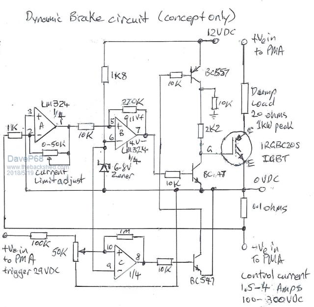 Also here is photo of my dynamometer with the dynamic module (blue) in MPPT mode. 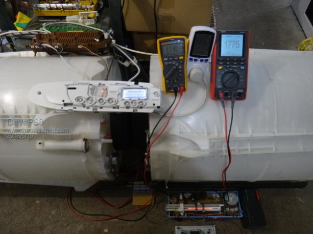 The white bread board very bottom of photo is the control logic circuitry with a MPPT table sorted in a EEPROM. There are realities if you do not accept, will lead to frustration because you will be spending time on wrong assumptions and the results cannot follow! The Dunning Kruger Effect :) |
||||
| BarkyJ Senior Member Joined: 26/04/2018 Location: New ZealandPosts: 114 |
Nice Dave, Thanks. My aim at this stage is to do a software controlled hardware, but your circuit looks very neat!! Today I got one of my stators, and rewired it to 2x6C, as now I think I am going to aim for a 48V system. I phoned the guy I purchased my AC/DC element off, and he said the ratings on the element are very conservative, and instead of aiming for 36V with a 900W limit, I could happily go up to 50V with over a 1KW. So I think I will aim for 48VDC as my FET's are rated to 60V, so give a bit of head room if things go a little south. Also means my cables will be a little narrower. I could also run it at 72V or so, if I put the 2 elements in series, rather than parallel. I asked about the regulations about DC, and he said that due to all the stuff happening with solar these days, at some point the legislation changed and now 120VDC is the limit before you need certification or the regulations come in, so thats rather neat. Unsure if anyone knows more info about this... So I put a nut on the end of the 2nd shaft, and then put a socket on my battery drill and spun it up. Easily in the 100's of volts DC unloaded. Connected my old 26ohm AC element to it, and haha - what a load, makes a huge different on the drill. Was quite eye opening actually. I then took the stator off and rewired it to 2x6C, and put it back together, and don't get as high a voltage now, but still go up to 200V on the battery drill on low speed. Next step is to start putting together a controller. I am still waiting for my FET's to arrive, but I did find a 55V 195A FET I have, which doesn't have quite as good characteristics, so I cant turn it fully on with my microcontroller, but will be good enough for a smaller load. I want to get some code written to change the PWM based on speed and just play and see if I can control the voltage. Time to put something simple together on vero board, and see what happens.  |
||||
| BarkyJ Senior Member Joined: 26/04/2018 Location: New ZealandPosts: 114 |
Here is a bit of a diagram of what I am planning to do. I may as well share it, and see if I can get some feedback from you experienced people. Potentially a different way of doing things compared to what has been done here, but potentially not. Not expecting this to be new, but I havent seen quite a setup yet. This is just a concept at this stage. Any concerns or obvious mistakes, please please speak up. Would love input, but so far I am quite happy with what I have here I think, but very much open to constructive criticism as I have not done this in practice yet obviously. 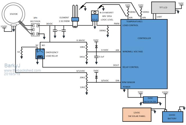 Essentially, Stator into 3 Phase rectifier (wiring and quantity etc still to be determined, but the end effect is the same). This then goes into some caps to filter a little, but since its just going into an element it doesnt need to be super lovely. Into the Element, and then that is switched in and out with the FET from the controller, based on voltage output and RPM information. Main voltage through a simple divider with some level of protection to clamp it to 5V, and into the controller. Voltage will be sampled in time with the FET being engaged, so each sample is at a time of load. RPM out of the stator pickups, into the controller. Voltage out of the stator also goes into a relay into a dump load, so if anything happens with the controller (such as the battery dies) then the dump load will engage and save the world... Controller is run off a 12V battery, which has an old car solar panel on it to maintain it. This is then regulated to 5V to power the controller, and also the LCD which will display all the infomation about the system. I will then also monitor temperatures of the FET and the Element, maybe other things, with some thermocouples Thats the plan so far. |
||||
| DaveP68 Senior Member Joined: 25/11/2014 Location: New ZealandPosts: 292 |
Circuit looks good and can't see any reason for that not to work as planned as long as the F&P stator are configured correctly. One very important detail that can be overlooked on F&P stators is they have a limited output current. At maximum current the stator will go into saturation and the torque drops off, so be warned don't go there!! That drop of in torque on a wind turbine will result in blade over speed (runaway) and could result in it destroying it'self... The optimum current as a rule on a Star 36 pole copper stator with black cap factory standard is 1.62 Amps DC out of the rectifier. Saturation occurs at about 40% above the optimum current level. I personally wouldn't let the current go any higher than 20 % above the optimum current level. Can see the stator in the photo is wired as a 2x6C Star. A 36 pole copper stator with black cap wired in Delta mode the optimum current increases to 2.8 Amps. Output voltage drops down by 57.7 % respectively. When the stators are rewired into other configurations such as 2x6C, 3x4C, 4x3C, 6x2C or 12x 1C the output current can be increased with a resulting drop on output voltage. To achieve 1 kW of power output at around 500 RPM from 2x F&P stators they must both be wired 4x3c Delta with the operating voltage being around 45 VDC with 22 Amps DC. Any deviation from this configuration will not give that output power due to load mismatch. There are realities if you do not accept, will lead to frustration because you will be spending time on wrong assumptions and the results cannot follow! The Dunning Kruger Effect :) |
||||
| BarkyJ Senior Member Joined: 26/04/2018 Location: New ZealandPosts: 114 |
Thank you David This is information I did not know and have not found on any pages... This stuff should be put on the main information pages, as that is valuable information. The main pages dont even show black rotor images, or suggest they are an option etc. Parts of the site seem very out of date... I guess everyone has day jobs etc, but it would be awesome to capture this sort of information. So with the 2x6C I have this stator in currently, then the optimum current is therefor 1.62 x 2 = 3.24Amps ? So 20% above that as a max is ~3.9A... Thats no where near as much as I thought I was going to get. P=VI = 48*3.9 = 187.2 Watts... right? How can that be... So what voltage is the optimum voltage for 2x6C? It suggests that it is suited for 48V systems, here: http://www.thebackshed.com/windmill/FPRewire.asp "Rewired as 6 coils in series. Again suitable for low speed turbine or high battery voltage ( 48 volts or above ). 36Pole 2X6C" The next question is, how do you find out what RPM this thing is going to even rotate at. From the load I experienced on the drill from just turning the rotor, its considerable. I was planning 1.5m blades, so say 3.2m total span, using the large PVC Pipe I have to start with. 2x3C Delta on Dual stators, operating at 45VDC, sounds perfect actually, but is this designed to run in light-moderate winds, or is this more of a high speed machine? I am ideally wanting it to run in light to moderate, but I really have no idea what I might experience. 45V @ 22A = 990W, which is perfect, I would eat that up all day long. I have seen posts with staggered stators etc, I assume this ended up not being as good as hoped? So dual 4x3C Deltas is the way to go? Is there an image/diagram of a 4x3C Delta configuration, around somewhere? Thanks |
||||
| DaveP68 Senior Member Joined: 25/11/2014 Location: New ZealandPosts: 292 |
Yes there is a bit of a lack of information on the main pages relating to what I brought up about optimum current etc. Here is a photo of a 6x2c Delta stator that I wiried up last year. 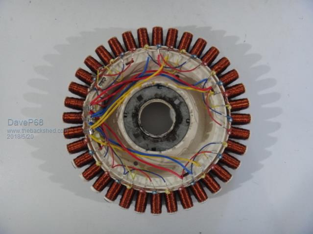 Will go into more detail in my next post as to why these operate the way they do. There are realities if you do not accept, will lead to frustration because you will be spending time on wrong assumptions and the results cannot follow! The Dunning Kruger Effect :) |
||||
| BarkyJ Senior Member Joined: 26/04/2018 Location: New ZealandPosts: 114 |
Hi Dave 6x2C Delta? Didnt you say 4x3C Delta was best? Sadly this forum compresses the images so much, its hard to make out alot of detail. I had been using imgbb.com and then posting the medium bb code directly in to the forum, so when you click on it you get a full image. Love to hear from you again :) |
||||
| DaveP68 Senior Member Joined: 25/11/2014 Location: New ZealandPosts: 292 |
It's just an example photo of how to wire a stator in Delta, as I didn't have a photo of a 4x3c wiring setup. Sorry about the resolution, as it's within the forum guidelines. If you use the colour coded Red, Blue, Yellow wires like I have, less chance of making a mistake (Delta wiring is a bit trickery). Remember Delta is in a triangle configuration of "Red Phase A end connects to Blue phase B end", "Blue Phase A end connects to Yellow phase C end" & "Yellow Phase A end connects to Red phase B end". There's enough detail there for you to follow the concept of how to wire both of your 4x3C Delta stators. Will provide more detail on how the current flow works in these F&P stators next post. There are realities if you do not accept, will lead to frustration because you will be spending time on wrong assumptions and the results cannot follow! The Dunning Kruger Effect :) |
||||
| BarkyJ Senior Member Joined: 26/04/2018 Location: New ZealandPosts: 114 |
Thanks Dave So with Delta, that typically requires higher winds before you reach cut in, right? So is that suitable for low to mid wind areas? If I understand it correctly, it will produce the most amount of power, but it also takes some wind for that to happen. I am just fearing that this will sit spinning under cut-in voltage, and not doing much good, most of the time. Is this where staggered setups come in to play, so you have say a Star system on one, and a delta system on the other, and merge the outputs, so you get some benefits of lower wind, lots of benefit at mid wind, and some benefits at high winds? I saw on another post of yours from a year or so ago, where you first posted up those tables, you mentioned 4x3C Delta 48V cut-in at 281RPM, and capable of producing over 650W @ 500RPM. I did some calcs to figure out what the tips of my blades might be travelling at to achieve 281RPM, and its around 47meters/second. That seems like it would be flying. Let alone 500RPM... Anyway, still chugging along. Made a prototype controller today and the passives etc for it to reduce the higher voltages to TTL levels for the controller, just about to connect it up to the windmill and see if I can get the RPM sensor outputting, and voltage reading coming in and adjusting the output PWM (without it yet controlling the load itself). Tested it out on my bench PSU and its increasing PWM when under voltage target, and reducing PWM when over voltage target, so the basic workings seem to be functional. |
||||
| BarkyJ Senior Member Joined: 26/04/2018 Location: New ZealandPosts: 114 |
Is this correct (THE BOTTOM SECTION ONLY)? Hacked the Star 4X3C image. { image removed by admin } I will change the other 3 also, if that one section is correct. |
||||
| BarkyJ Senior Member Joined: 26/04/2018 Location: New ZealandPosts: 114 |
Is this correct?: { Image removed by admin } Hacked the Star version. |
||||
| DaveP68 Senior Member Joined: 25/11/2014 Location: New ZealandPosts: 292 |
All I can say is don't try and hack a perfectly good drawing of a star stator, just start from scratch to avoid confusion for others who may come across this post in the future. Looks like the part you did try to draw in delta mode is correct. Back to my point about current flow in these F&P stators. The vast majority from what I can work out on this forum, try to connect these stators via a rectifier to charge batteries. That creates a whole set of problems if you wish to yield the maximum performance from these stators. When F&P stators are connected to a battery, ONLY the current can increase once the terminal voltage has been reached. There are 2 problems that arise from this practice. First is to achieve a cut in of say 100 RPM the stator needs to be wired for 1x12C Delta on a 48 VDC system. For a single stator the maximum current even in saturation will be 4 Amps DC so power output is limited to 192 W peak. The reason the power doesn't increase above 200 W for this example is the voltage is clamped by the battery terminal voltage. Lets say for a single stator on a 48 VDC system you wanted to get 550 W of power at 500 RPM. As it turns out the stator would be wired as a 4x3C Delta. The cut in would be just under 300 RPM though. The compromise on here when trying to directly charge batteries is to use a dual setup of 1x12C plus 4x3C with the peak output power probably being 800 W if we get to 550 RPM. Your system is trying to emulate what I've already achieved utilising a form of MPPT using PWM to switch a high power resistive load to heat water. My advice is to keep your bade diameter to no greater than 3 m due to the swept area being too large above that (too much power too control). Depending on how you shape the blades the Tip Speed Ratio you may end up with at a guess will be close to 7 to 7.5 if they tapper from root to tip. That will make the cut in of 110 - 140 RPM in a wind speed range of 2.5 to 3 m/s. This means with the Dual 4x3C Delta stators will produce usable start voltage of around 20 VDC with 1 to 1.5 of current to draw from them. When the wind picks up to around 10 m/s (36 kph) you get 500 RPM on the shaft with around 1 kW power output, hence my calculation of 45 VDC at 22 Amps. If the wind increases beyond 12 m/s (43 kph) then too much torque will be produced on the shaft for the stators to take and you could start to get blade runaway. Hope you plan to use some form of mechanical furling system. Have a solution to the torque problem. These F&P stators can produce 2.5 W per RPM with some external modifications. That would translate to 2 - 2.5 kW of peak output power at 500-559 RPM keeping things in check in high winds. Torque stay in the controllable range with this modification  There are realities if you do not accept, will lead to frustration because you will be spending time on wrong assumptions and the results cannot follow! The Dunning Kruger Effect :) |
||||
