
|
|
Forum Index : Windmills : My unorthodox Build
| Author | Message | ||||
| Warpspeed Guru Joined: 09/08/2007 Location: AustraliaPosts: 4406 |
[quote]The plan is to get a 6m length of the mast's steel, and cut it in half an implement a hinge like many of you guys have done before, so I can fold it down to service it on the ground. But those details are still a Work In Progress.[/quote] Should be possible to rotate that, and even keeping the hinge in the middle should also be possible, but the hinge would need to be very well engineered not to introduce slop at the hinge. Wide spaced hinge pins should solve that. A heavy tapered roller thrust bearing at the base should be dead easy. If its all thought through it may actually simplify things rather than add to the complexity. Cheers, �Tony. |
||||
DaveP68 Senior Member Joined: 25/11/2014 Location: New ZealandPosts: 292 |
Hi James The 6m length of the mast's steel you plan to use, will it be self supporting or use guy wires secured to ground anchor points? There are realities if you do not accept, will lead to frustration because you will be spending time on wrong assumptions and the results cannot follow! The Dunning Kruger Effect :) |
||||
| BarkyJ Senior Member Joined: 26/04/2018 Location: New ZealandPosts: 114 |
Hi David Yep plan is to use guy wires. It might self support OK, I am not sure, but the plan is the use guy wires just to keep things a bit more supported. Still need to figure all that out too, as the ground it is going on is not flat, its on a bank, so I need to walk the land and figure out the positions of everything yet. Guy wires seems like a safer option than self supporting, even if the pole ends up being capable. We shall see I guess. |
||||
| DaveP68 Senior Member Joined: 25/11/2014 Location: New ZealandPosts: 292 |
All good. The whole project is coming along nicely from my armchair view  As per another discussion re the maximum amount of torque each stator will take, have done some more tests on a 1x12C Delta at various RPM/power levels. At 500 RPM the stator output power was 539 W (192.5 V at 2.8 Amps DC) and got an input torque reading 12.6 Nm. A result I've replicated in the past and 82% efficiency. Run it up to 575 RPM the stator output power was 622 W (192.5 V at 3.23 Amps DC) and the input torque increased to a maximum reading of 14 Nm. Drops down to 73% efficiency. Run the test again at 1200 RPM (drill direct drive mode) output power was 770 W (192.5 V at 4 Amps DC). This is full stator saturation and the input torque dropped off a cliff all the way down to 7.5 Nm!! I've never actually done any detailed testing on F&P stators outside what I considered their most efficient mode of operation. The big surprise was the stator was still operating at around 82% efficiency! The blades certainly won't want to operate for that long at 1000 + RPM... There are plenty of comments on this website about F&P wind turbines going out of control when the core becomes saturated and other remarks like you can't put a short circuit on the output to stop them etc... The point I'm trying to get across here is to let the stator(s) output voltage rise to level it needs to and not let the current exceed 3.3 to 3.4 Amps (2.8 amps is the optimum 1x12C Delta). At high RPM the torque will stay in the 12-14 Nm range per stator and we should be able to avoid any unwanted saturation.  Anyway this latest information is to provide a better understanding of the operating envelope F&P stators and not intended to put anyone off using them on a wind turbine due this operating limitation. We all learn something new every day. I'm sure plenty of others out there have been there done that in regard to whats posted above. There are realities if you do not accept, will lead to frustration because you will be spending time on wrong assumptions and the results cannot follow! The Dunning Kruger Effect :) |
||||
yahoo2 Guru Joined: 05/04/2011 Location: AustraliaPosts: 1166 |
Free standing poles with small turbines on the top are very vulnerable to rocking, it is quite difficult to tune it out. the vortex of turbulent air behind the pole oscillates like a top loader washing machine and creates alternating lift on the pole. It needs a flow breaker that spirals down the pole or a couple of tensioning wires.  sigh!..... that is not how they work. A plain old satellite actuator will move the shaft 3+mm per second at 5000 newtons. The solar actuators i have used will move a tonne and hold 2 tonnes. if you matched the linear reduction with a old drill planetary the most it would take for a full revolution is eight minutes. there are plenty of options available with some scrounging and lateral thinking. 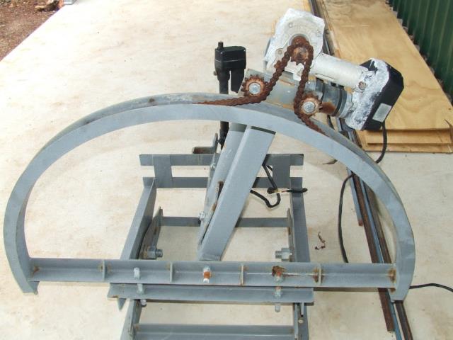 I'm confused, no wait... maybe I'm not... |
||||
| Warpspeed Guru Joined: 09/08/2007 Location: AustraliaPosts: 4406 |
So you could probably build a solar tracker that went from horizon to horizon in ten seconds. But why would anyone need something that does that ? Once it locks onto the sun path, fifteen degrees per hour is all you need to follow the sun. Cheers, �Tony. |
||||
Madness Guru Joined: 08/10/2011 Location: AustraliaPosts: 2498 |
You need to hurry up if it is leveling to avoid wind damage if a storm comes in quickly. There are only 10 types of people in the world: those who understand binary, and those who don't. |
||||
| yahoo2 Guru Joined: 05/04/2011 Location: AustraliaPosts: 1166 |
A solar tracker would run for 3 seconds every seven minutes and park level in less than two minutes. the challenge with a turbine is going to be tweaking the furl/wait/unfurl timings in hot gusty conditions. I recall someone doing it with blade pitch control and it worked really well, I am sure it is on this 4m. found it frans AKA Midwoud1 posted some detail on otherpower.com active pitch control 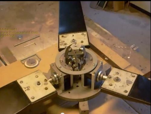 I'm confused, no wait... maybe I'm not... |
||||
| Madness Guru Joined: 08/10/2011 Location: AustraliaPosts: 2498 |
One way to do it would be to take an ongoing average reading of wind direction over say 5 minutes and make any direction adjustments to the average. There are only 10 types of people in the world: those who understand binary, and those who don't. |
||||
| Warpspeed Guru Joined: 09/08/2007 Location: AustraliaPosts: 4406 |
Somewhere on the Internet I saw a variable pitch setup that used a cordless drill motor + gearbox + chuck, that turned a leadscrew, that operated a fairly simple variable pitch mechanism. Feathering the blades completely might be another approach to the whole storm problem. And it would also open up a whole new world of matching the blades to the F&P. Cheers, �Tony. |
||||
| DaveP68 Senior Member Joined: 25/11/2014 Location: New ZealandPosts: 292 |
Reason for bringing up a free standing tower as a discussion point is if the turning system is mounted at the base of the mast will complicate the attachment of guy wires. Mounting motor that turns the turbine into the wind at the top of the mast seems the logical thing to do along with using guy wires. There are realities if you do not accept, will lead to frustration because you will be spending time on wrong assumptions and the results cannot follow! The Dunning Kruger Effect :) |
||||
| DaveP68 Senior Member Joined: 25/11/2014 Location: New ZealandPosts: 292 |
Hi James The data that I've emailed to you for the "MPPT based dynamic equation" relates to this Torque vs RPM calculation graphed below. 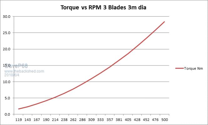 The blade TSR should be around 7.5 in order to match the RPM and close enough is good enough. Also made a guess of 30 % blade efficiency. I did the same calculation for Fred (flc1's) on his F&P triple stator wind turbine using the 4x GOE 222 blades and he got some very results. Maximum accumulated output power produced over 24 hours was 8 kW/hours, averaging over 1 kW/h a day and the peak power power reached 2.5 kW! Fred's wind turbine wasn't even in a windy location with an average wind speed of around 12 kph. David There are realities if you do not accept, will lead to frustration because you will be spending time on wrong assumptions and the results cannot follow! The Dunning Kruger Effect :) |
||||
| Boppa Guru Joined: 08/11/2016 Location: AustraliaPosts: 814 |
Spinning the whole mast isnt an issue even with guy wires, radio enthusiasts have been doing for it for decades You put a bearing (preferably a 2 piece inner/outer type, I used a truck/buses front wheel bearing that was a perfect fit on the pipe , inner ring is attached to the mast with a sleeve bolted to the mast under it to spread the load. Some made a plate to hold the outer, I cheated and just welded some cut up chain links to the outer sleeve and used those to attach the guy wires. Turning mechanism in my case was an old ford transit diff, started with the armstrong method (tailshaft through the wall of the shack), but eventually went electric with a dc motor on the diff It was 15m high, with 3 separate guy support points up the mast |
||||
| BarkyJ Senior Member Joined: 26/04/2018 Location: New ZealandPosts: 114 |
I am on to blade design at the moment. Having a bit of 'fun' - hmm. So I am going to be using this large diameter thick walled pipe to start off with. Based on the RPM and power etc wanted, the TSR should be ideally around 7.5ish. I have found 3 online calculators so far, which all output fairly similar things, one was designed specifically for pipe blades, where you can enter the diameter of the pipe, TSR, radius, yadda-yadda, and it outputs an SVG file which you can print 1:1 on a few sheets of paper, cut it out and then trace on the surface of the pipe. What I got though was quite a behemoth. Had a massive 190mm or so tip, which tapered up to a massive 380 at the root, before tapering back for mounting onto the hub. This just seems massive, for a 1350mm length blade. From what I understand, on these sorts of blades, the root is what assists with low wind starts, and the tips are tapered to reduce noise. Here is a reference I found, some good stuff on the last page: http://www.scoraigwind.com/wpNotes/bladeDesign.pdf The calculator that I used to print off this blade shape, was here: http://www.windandwet.com/windturbine/tube_blade/design.php I have seen the Warlock.com.au one too, but that seems more for real blades, not pipe blades. If I was to go with the GOE222 blades, then to get a TSR of 7.5 or so to match the stator setup, then it would seem I would only need a 2 blade setup, rather than 3 that I am planning for now. 10/sqrt(2) = 7. But would a 2 bladed GOE222 work OK... I don't want to go there yet, just planning for what is likely going to be the inevitable though. Given my pipe is 630mm diameter with an 18mm wall, I could sculpt them quite nicely to be better than just a thin PCV pipe would be, but stll the question remains as to what sort of shape is right. What I had originally drawn down was more like Gizmo's 6 bladed setup he had on his dual stator windmill, on this page: http://www.thebackshed.com/Windmill/articles/GlennL.asp I am thinking about a 50mm tip width or so, going up to maybe 160-190mm sort of root, then tapered back a bit for mounting onto the hub, with steel bracing about 1/3 up the blade back to the hub for extra support. Does this seem like a valid place to start? |
||||
| Warpspeed Guru Joined: 09/08/2007 Location: AustraliaPosts: 4406 |
Although I was a student pilot once, aerodynamics is not really my field. However the jet fighter design guys talk a lot about wing loading and area to weight ratios, and with the turboprop aircraft, as horsepower keeps on rising, the propeller blades are becoming a lot wider and a lot more ugly. 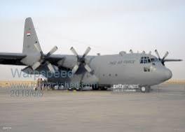 Seems to me that with a wind turbine, generated torque might very well increase with blade chord width as well as blade diameter and number of blades. I suppose it depends if aesthetics are more important than performance... How about cutting up a piece of humble 90mm rainwater pipe first, and make a very small scale model, and see how that turns out ? Cheers, �Tony. |
||||
| BarkyJ Senior Member Joined: 26/04/2018 Location: New ZealandPosts: 114 |
Well as long as they turn and make reasonable power, then really I don't care too much what they look like, to be honest. When they are spinning it just looks like a transparent circle anyway. The body is going to be so sexy (cough cough) it can share some of its sexy-ness with the ugly blades if required - lol. Honestly though, at this stage of the game, I don't mind what they look like, as long as they work to a reasonable degree. Humble drainpipe I am unsure what it will prove though. I got this massive pipe for free, so I may as well attempt to use it. Because normal drain pipe will be so different in profile, I'm not really sure how to compare one to the other anyway. Plus its so thin, whereas this big pipe is thick-as-bro... Not sure what is best |
||||
| BarkyJ Senior Member Joined: 26/04/2018 Location: New ZealandPosts: 114 |
Here is a pic of what that calculator came up with, paper cut and sitting on top of the Pipe. 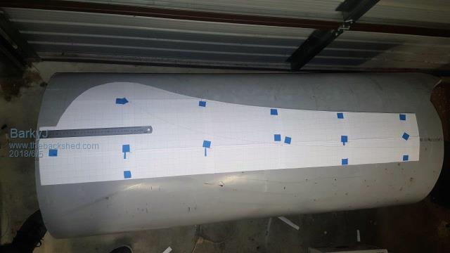 Massive. |
||||
| Warpspeed Guru Joined: 09/08/2007 Location: AustraliaPosts: 4406 |
[quote]Humble drainpipe I am unsure what it will prove though.[/quote] Probably nothing, but it should give you a better idea of what its going to look like in three dimensions. I tried this myself a long time ago out of curiosity, but there was nothing scientific about how I did it. One thing I quickly discovered is that once you cut a circular pipe into a flat strip, most of the stiffness disappears. Cheers, �Tony. |
||||
| yahoo2 Guru Joined: 05/04/2011 Location: AustraliaPosts: 1166 |
thin walled pipe blades are not aerodynamic despite what most of the sellers say. if you can get any sort of aero shape out of your thick walled pipe you are well out in front. those blade with the beer belly curve down towards the root work on small low speed turbines BUT they also have a twist in the blade so the angle of attack is much steeper down there to cater for the low blade speed close to the hub. nothing to do with low wind speed. the link I posted to the pitch control has some profiles of some aero shapes a few pages in (before page 12 I think) you might find a stubbier profile that fits the pipe better than the geo-222 95% of the power comes from the outer third of the blade, taper is not that important. When your blades hit their speed limit the last couple of inches might progressively lose lift, this is where the noise comes from. there is a technical term for it that I have forgotten. I have worked on a few 2 blade turbines, they scare the hell out of me, three blades make the rotor much more stable. I wouldn't over think this, you want as much lift as you can get on the outer third of the blade to get the best low-medium wind performance, you will NEVER use the blades potential in high winds you will always be speed limiting above the 9-17 m/s range I'm confused, no wait... maybe I'm not... |
||||
| DaveP68 Senior Member Joined: 25/11/2014 Location: New ZealandPosts: 292 |
I'm with Tony on this current blade discussion. Wider and a lot more ugly isn't going to serve James requirements due to the possibility too much not enough RPM. The upper Torque limit that the Dual F&P stators can take without any other modifications is about 28 Nm at 400-500 RPM. I think there is merit in making some scale blades out of a short piece of 90 mm diameter PVC drain pipe like Tony suggested. Yes the upper limit of what I've calculated for James is 10 m/s anyway, the speed control can certainly start from 9 m/s and the Blade TSR becomes less important. The home made controller which controls the output load sort of on a MPPT based dynamic equation still needs to know the TSR how I understand it. James you can back up on this one? There are realities if you do not accept, will lead to frustration because you will be spending time on wrong assumptions and the results cannot follow! The Dunning Kruger Effect :) |
||||
