
|
|
Forum Index : Microcontroller and PC projects : PWM gaps?
| Author | Message | ||||
| Malibu Senior Member Joined: 07/07/2018 Location: AustraliaPosts: 162 |
MORE complicated? I though it was complicated on the last one!  Thanks Geoff  John |
||||
| Geoffg Guru Joined: 06/06/2011 Location: AustraliaPosts: 3167 |
OK, I have had another shot at this (beta 6). As before it can be downloaded from: http://geoffg.net/micromite.html#Downloads. The issue comes about because of the way the PWM output is generated. A counter counts upwards and on each increment it is compared to a register. If they are equal the counter is reset to zero and starts counting up again - this is what controls the frequency. The problem occurs when you increase the frequency. For example, the counter might be at 900 and the register is set to 1000. If you change the register to 800 there will be no match and the counter will continue to its limit (65535) before resetting and during this time the output will not change (ie, the "gap"). The simple answer is wait for the counter to reset to zero and then update the register. The problem with this is that at low frequencies it could be up to 50ms before this happens and MMBasic will freeze while waiting, so a more complicated solution is required. On top of this there is another issue at higher frequencies - the counter might be at zero for such a short time that the firmware cannot see it (which is the current problem). I have tested beta 6 and it seems good but I think that your steppers are more sensitive to these momentary glitches so I would be grateful if you could test beta 6 and report back. BTW, there is a change in the counter setup (and the update algorithm) at 1250Hz or above, so there could be a glitch when moving up or down through this frequency. Please let me know if you see it. Thanks, Geoff Geoff Graham - http://geoffg.net |
||||
| Malibu Senior Member Joined: 07/07/2018 Location: AustraliaPosts: 162 |
All I can say is "Brilliant!"  I didn't even bother to hook up the DSO to check the pulses because it ran so sweet out of the box, there was no need. Notice in the code that my set RPM is 2900? I have the stepper ramping up and down between 6 and 2900RPM and in 100+ cycles, it hasn't skipped a beat. (Actual speed is 2901 RPM - the fastest I've driven a stepper) There's no sign of the 1250Hz problem - if it's there, the motor cruises through it with no problems. I even set the STEP between 1 and 50 without any problems. I suspect I could push the motor parameters a little more and still get away with it (...and I might, just for the fun of it  ). ).Thanks Geoff, that's a brilliant piece of work  John |
||||
| Malibu Senior Member Joined: 07/07/2018 Location: AustraliaPosts: 162 |
Just for interest, I pushed things a little harder and managed to get a no-load speed of 3860RPM out of the motor. (Mostly regular with only around 10% of cycles missing steps causing a stall) That's a PWM frequency of 205Khz and 50% duty I only realised I wouldn't get much more when I hooked up the DSO and saw a pulse width of 2.2uS - the driver board needs 1.9uS minimum so it's really running on the limit! I'm impressed  John |
||||
| Geoffg Guru Joined: 06/06/2011 Location: AustraliaPosts: 3167 |
Thanks John, great news. Another bug squashed. Geoff Graham - http://geoffg.net |
||||
Azure Guru Joined: 09/11/2017 Location: AustraliaPosts: 446 |
Great news. Those ramps up and down are very accelerated and should show up the problem if it exists. Just for completeness you should run it with a pause in between steps to make sure it is also smooth on a slower ramping. And out of curiosity what does the latest firmware do with Geoff's short step up/down loop. |
||||
| Malibu Senior Member Joined: 07/07/2018 Location: AustraliaPosts: 162 |
A little further testing this morning... PWM 1, 3000, 25 PWM 1, 3010, 25 No problems at all. The same code in Beta5 had the motor ready to leap off the table. Beta6 and it runs smooth as silk. I did all that yesterday and couldn't fault any of the ramping in slow speeds right through to fast speeds with long pauses, short pauses and a whole bunch of variations of a theme. I even tried STEP 500 and it reached top speed virtually instant. Eventually, I could get the motor to stall, but that was pushing things WAY beyond what should be considered 'normal' (ie: STEP 160000 is a little too much, but defeats the purpose of adding any Ramp Up anyway) I see it. Having said that, it wasn't noticable on yesterdays testing, but that was a speed range of dead-slow up to super-fast. I knocked up some code this morning for testing (complete with my notes) print "1250Hz Range" 'Notes: 'BaseHz=1246; Good signal > Motor growly, but probably magnet click. 19 Good Pulses 'BaseHz=1247; Good signal > Motor growly, but probably magnet click. 19 Good Pulses 'BaseHz=1248; Signal Chopped > Wide 1st Pulse, 10 good pulse, 1 slightly narrower pulse, 1 spike, 4 good pulse | Regular Pattern 'BaseHz=1249; Signal Chopped > Wide 1st pulse, 4 good pulse, 1 narrower pulse, 1 spike, 11 good pulses | Regular Pattern 'BaseHz=1250; Good Signal > Motor Growly (Magnet click?), 20 good pulses. 'BaseHz=1251; Good Signal > Motor Growly (Magnet click?), 20 good pulses. BaseHz=1249 for j = 1 to 500 for i = BaseHz to (BaseHz+2) pwm 1, i, 50 pause 5 next i pwm 1, stop pause 10 next j pwm 1, stop pause 1000 print "1250Hz" pwm 1, (baseHz+1), 50 pause 10000 pwm 1, stop (Edit: Ooops, I hit the post button too soon) It only comes in to play and is noticable AT the 1249 to 1251 range. That's also an unlikely scenario to ramp up from 1249 to 1251 as minimum speed set to maximum speed set. Speeds will pass through that range, but only on the way to a faster speed. If you're happy to fix it Geoff, I'm happy to test it - but for my purposes it does what it should John |
||||
| Malibu Senior Member Joined: 07/07/2018 Location: AustraliaPosts: 162 |
Here's the waveform with BaseHz set to 1249 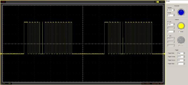 John |
||||
| Azure Guru Joined: 09/11/2017 Location: AustraliaPosts: 446 |
I am not sure what that first long pulse is from, it should be the same as the ones after it. At 1249Hz the pulses are about 0.8ms, so there are about 5 pulses before it changes to 1250Hz which is right where the second glitch is. Then 1250 to 1251 looks smooth (5 more pulses each with a clean tranistion. |
||||
| Malibu Senior Member Joined: 07/07/2018 Location: AustraliaPosts: 162 |
Agreed... I presume it's how the register is first loaded and the way the PWM is initialised. Run this code, BaseHz=1000'1249 for j = 1 to 500 for i = BaseHz to 1300'(BaseHz+20) pwm 1, i, 50 pause 5 next i pwm 1, stop pause 10 next j pwm 1, stop pause 1000 ... and you get this... 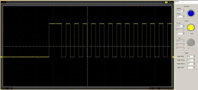 When it periodically shows up, it's always a wide pulse on the first cycle (similarly at the other end, there's often a narrow pulse on the last one - presumably that's depending on when the PWM is turned off). The set frequency is perfect from the falling edge of the wide pulse to the next falling edge. Not a big deal for my situation, but could be an issue trying to control servos when they need a precise mark/space. John |
||||
| Geoffg Guru Joined: 06/06/2011 Location: AustraliaPosts: 3167 |
This is interesting. When I first implemented PWM I was thinking that it would only be used for generating a voltage or sound. But driving a stepper is a valid application and it needs to be done right. I don't have a stepper to test so thanks John. I can see three issues: - the first pulse is double width. - there is a glitch at 1250Hz. - the last pulse (at shutdown) can be short. I have ideas for fixing these. Let me have a play and I will get back to you. Geoff Geoff Graham - http://geoffg.net |
||||
| Malibu Senior Member Joined: 07/07/2018 Location: AustraliaPosts: 162 |
Thanks Geoff I was starting to feel guilty that I was putting you through all the bother!  The reason I pounced on the MM system is specifically the PWM. Most PWM driving has a set frequency and the duty cycle is changed (ie: servo's), which is useless for driving steppers - your design can change frequencies and keep the duty cycle constant and as it turns out, that's perfect for driving STEP/DIR stepper systems. It's especially good with the driver chips that are out there now (Like the DRV8825, DRV8885 & bunches of others) (I started typing a whole <blah-blah-blah> on your 3 issues, but I'm sure you've got it all covered  ) )Although, one possible future idea for the firmware could be a stepper function. No worries, let me know and I'm happy to run it through its paces on my test rig...  For your interest, so far this stepper has been running a continual [ramp up-ramp down] cycle since around 9:00am and hasn't skipped a beat. John |
||||
| Azure Guru Joined: 09/11/2017 Location: AustraliaPosts: 446 |
I am interested in both the stepper driving and the project you are trying to build (coil winder). I might have to get some extra hardware to get hands on with it and not just watch a PWM pulse train |
||||
| Malibu Senior Member Joined: 07/07/2018 Location: AustraliaPosts: 162 |
Go for it! It's always more fun getting things happening than trying to figure out problem! John |
||||
| KeepIS Guru Joined: 13/10/2014 Location: AustraliaPosts: 1400 |
FYI I'm currently driving 3 stepper motors with an MM plus @ 120 MHz. I'm using two PWM outputs and ramping up / down driving the Pulse pin of two Stepper driver modules. It's a closed loop system in that the position of the steppers is determined by two sets of digital slide scales, I'm also reading / decoding the scales directly with the MM. It's likely the reason that I don't have an issued with or even noticed any PWM glitch. Running the PWM from 50 up to 6000 Hz and always a constant 50 duty cycle. Both scales and 3 motors are running what could be basically described as a dual axis CNC. Resolution and accuracy down to 0.01 mm, more that enough for this hobby application. Love the MM plus with a 7" touch screen for applications like this. All credit to Geoff for his brilliant design and MMBasic. It's all too hard. Mike. |
||||
| Azure Guru Joined: 09/11/2017 Location: AustraliaPosts: 446 |
@KeepIS Sounds like a great setup. What modules are you using for the stepper motors drivers and any more details on the digital slide scales? |
||||
| KeepIS Guru Joined: 13/10/2014 Location: AustraliaPosts: 1400 |
Hi, I'm using two DM542T Digital stepper drives in the system, one unit is driving two Steppers in parallel, and no, I don't have any real issues with driving two in parallel, I have to keep the maximum speed down slightly though, and even that is due to driving two motors at half current. Using Nema 23 425oz-in 4.2A steppers and a 400 Watt 36V SMPS. The Slide scales are from the low cost iGaging Easy-View DRO series. You likely know of them, they come with their own small Display head controller, I don't use the supplied small control head, I clock and read them directly. Using low cots Bearing rails and steppers are connected to Screw and Ball nut drives. It's all too hard. Mike. |
||||
| Malibu Senior Member Joined: 07/07/2018 Location: AustraliaPosts: 162 |
Sounds like an interesting project KeepIS! I checked out the Stepper drives you mentioned and yeah, there's plenty of similar and all are really good (I run Gecko drives on my CNC and they are fantastic!) I looked into the option of some of the Gecko drives for what I'm doing, but it adds to the cost, so for 5 bucks on e-bay... the 8825's win the day The Easy View system looks pretty good! Typical of that linear encoder systems for use on milling machines - always a good way to get readings... I like 'em, I'll have to keep them in mind, thanks It's interesting you didn't have any problems, and also interesting that Azure didn't either. When I tweaked the code so that the PWM had feedback to an interrupt pin so the PWM value ONLY got changed after the pulse occured, my problem cleared up as well. I guess I created a closed-loop by doing that as well, so you could be right in your assumptions. Eventually, I'll be using a quadrature encoder on my steppers, so it will become a closed loop as well. (Right now, I'm trying to settle down the reading from the pot to get a nice steady RPM's... Arrrgh!, I hate noisy pot wipers!) Thanks for the extra ideas John |
||||
| KeepIS Guru Joined: 13/10/2014 Location: AustraliaPosts: 1400 |
Hi John, I'm assuming that you have a cap from the wiper to either side of the pot, but thought I'd mention it just in case. That's also another reason why I hate low cost mechanical encoders, trouble is good quality optical encoders are expensive, well at least for me. I using two encoders for micro adjustments of the drives in manual mode, most of the time you just punch in the position or offset on the MM screen and press go. I do have a couple of quality Encoders for motor shaft or similar mounting, which is what you intend to do with the feedback loop, but they are hard to mount / use in my current situation, so a couple of Jaycar low cost mechanical specials are in there. I'd better let the thread get back on track. Cheers Mike. It's all too hard. Mike. |
||||
| Geoffg Guru Joined: 06/06/2011 Location: AustraliaPosts: 3167 |
Another update for the beta version (it is now at beta 7). This fixes the double width pulse when the PWM starts and the short pulse when it is stopped. It also fixes the short pulse that occurred when changing the frequency from <1260Hz to above (and vice versa). The only problem is that when this is done there is one missing pulse. I have worked on this but it seems to be a "feature" of the PIC32 timer and compare modules which generate the PWM stream. The new beta can be downloaded from: http://geoffg.net/micromite.html#Downloads Look for "Micromite Firmware V5.04.10 Beta Test Version" Let me know if you find anything else (fingers crossed again). Geoff Geoff Graham - http://geoffg.net |
||||
