
|
|
Forum Index : Microcontroller and PC projects : PWM gaps?
| Author | Message | ||||
| Malibu Senior Member Joined: 07/07/2018 Location: AustraliaPosts: 260 |
Thanks Geoff  I'm pretty crook at the moment, so give me a couple of days and I'll knock up some test code - I'll let you know how it gets on (I'm sure it will be fine!) John |
||||
| Geoffg Guru Joined: 06/06/2011 Location: AustraliaPosts: 3281 |
I hope that it is not anything serious. When said "changing the frequency from <1260Hz to above" I should have said "changing the frequency from <1250Hz to above" Geoff Geoff Graham - http://geoffg.net |
||||
| Malibu Senior Member Joined: 07/07/2018 Location: AustraliaPosts: 260 |
Nah, it's all good Just a dose of the gastro that's been going around (I think my problem now is that I haven't eaten in 2 days!) John |
||||
| Malibu Senior Member Joined: 07/07/2018 Location: AustraliaPosts: 260 |
Sorry Geoff, I'm not sure what's going on with this version... I can't quite put my finger on a reason, so I'll give the facts and see where it goes from there. A couple of days ago I had a piece of code to read a pot value, convert to PWM frequency and ramp up/ramp down to that value. If the pot value changed, so did the motors revs - and everything worked well. I downloaded Beta 7 this morning and flashed the MM. Knocked up some code (A long story, but this is what I finished with) option explicit Dim StartHz, EndHz as integer dim i, j as integer pwm 1, stop 'Steady20Hz 'Range1000To2000 'Range100To1000 Range20To1000 'Range20To100 do:loop sub Steady20Hz pwm 1, 20, 25 end sub Sub Range1000To2000 do for i = 1000 to 2000 pwm 1,i,25 pause .1 next i pwm 1, stop pause 10 loop end sub Sub Range100To1000 do for i = 100 to 1000 pwm 1,i,25 pause .1 next i pwm 1, stop pause 10 loop end sub Sub Range20To1000 do for i = 20 to 1000 pwm 1,i,25 pause .1 next i pwm 1, stop pause 10 loop end sub Sub Range20To100 do for i = 20 to 100 pwm 1,i,25 pause .1 next i pwm 1, stop pause 10 loop end sub Running "Range20To1000", here's the waveform ... (Remember, this is using Beta 7) 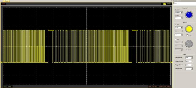 If you comment in and out the various calls to the subs, you'll see there's a variation on the same theme - The worst offender is the "Range20To100". ...So, I loaded the code I had running a few days ago, and it certainly wasn't happy either. A very jumpy motor tone and seemed to be running a higher temperature on the motor. I went for a bite to eat and a think and when I came back the motor was sitting on the pad 45 degrees angle to what I left it at, which tells me that there's some serious stepping glitches happening (the momentum of the pulling up a motor makes a tiny jump) So...... back in with Beta 6 and here's the "Range20To1000" code again. 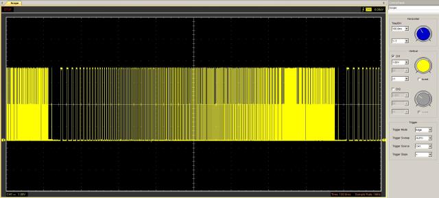 It's hard to see, but the first picture is a 50m/s timebase and the second is 100m/s timebase yet running the same code. Moving on, it's back in with the motor code from a couple of days ago running on Beta 6 and it's all sweet again. As I said first up, I'm not sure what's going on!  Two things I noticed - first, a straight call of PWM 1, 20, 25 ... gives a nice waveform, and second, the 1250 glitch was certainly missing in Beta 7, but also seemed to jump Hz from 1247 to 1257. Maybe it's me or my DSO but that's what I could see. Anyway, I'd love to offer my thoughts on what's going on, but I'm stumped on this one! John |
||||
| Geoffg Guru Joined: 06/06/2011 Location: AustraliaPosts: 3281 |
I'm stumped also. Looking at my oscilloscope traces it looks fine but there must be something going on that your servo is reacting to. I will try to get the time to put a logic analyser on to it - that will allow me to check one sweep in detail. The problem is that I am running out of time. I leave in a week for Europe and will be gone until the end of September. It might be best to simply revert to the beta 6 code and leave it there. EDIT: Something just jumped out at me. Your loops have a delay of only 0.1ms, that is very short. Your Range20To100 has 80 steps and thus they are all completed in a little over 8ms. BUT the period of the first cycle (at 20Hz) is 50ms, so the whole thing is over before the first cycle has completed. This seems ridiculous, have I got it wrong? Your other code ran at higher frequencies and had delays of 5ms, enough to get out several cycles before a frequency change. I never thought of testing it with such rapid changes - maybe the answer lies there. Geoff Graham - http://geoffg.net |
||||
| Malibu Senior Member Joined: 07/07/2018 Location: AustraliaPosts: 260 |
Not a problem Geoff You've done heaps already and Beta 6 runs perfect as far as the motor turns go. It's only nit-picking because the trace 'says' there's a problem. I've re-flashed with the backup I made of 6, so I'm good to go with that. Re the edit... This is 0.1ms delay, but I also dabbled with longer delays with the same results. I only went down to 0.1 to try and get the pulses closer together so I could capture the trace easier on the DSO. It wouldn't explain why the 'working' motor code wouldn't work on Beta 7 though... I have another kit for an MME64 (What can I say, I like these so much I bought 3 more kits!). Leave it with me and I'll put together another E64 loaded with Beta 7. I can play around at some point and see if I can nut out what's going on (...and yeah, I'm happy to put my hand up and say it's my code!  ) )Don't stress, enjoy yourself in Europe and forget my badgerings! John |
||||
| Geoffg Guru Joined: 06/06/2011 Location: AustraliaPosts: 3281 |
Well, I doubt that the code that you presented would work on beta 6, or any version. Do you have a simple bit of demo code (just a few lines) that works on beta 6 but not 7? Geoff Graham - http://geoffg.net |
||||
| Malibu Senior Member Joined: 07/07/2018 Location: AustraliaPosts: 260 |
G'day Geoff, Ok, you're correct in that the 0.1ms is too quick for the 20Hz PWM. So far, i haven't used down to 20 (minimum has always been 530; around 5 RPM) so never really concerned myself with what was happening below that figure. The 0.1mS was just to speed the frequency change up to make things happen faster. Plus, I only used 20 in Beta 7 to do a thorough test as promised Sorry for the delay, I knocked up another E64 so I could have a B6 & B7 on hand to easily swap them around. Ok, here's the results : The code option explicit dim i as integer do for i = 20 to 128000 step 500 pwm 1,i,25 pause 50 next i pwm 1, stop pause 150 loop ...Changed from 0.1ms to 50ms with a step value of 500 to ramp up pretty fast. 20 is an RPM of 0.1875/min and 128000 is 1200/min Here's the B6 waveform 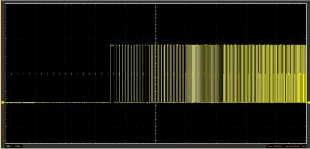 The first wide pulse is 2.9mS wide and MAY be a remnant of the 20Hz PWM, but I can't be sure. Each change in errr... 'texture' (where the frequency changes and so the colour changes) corresponds to the 50mS pause value and the frequencies increase by the step value. All good there... Here's B7 waveform running the same code 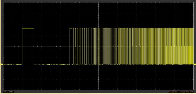 Again, the first 2 pulses are probably the 20Hz remnants and the same 'pattern' in both waveform recordings. Also shown is the gap in the 1250Hz All I can see that MIGHT be another glitch is that I change frequencies ad-hoc and may cause the last pulse to be out of sync with the next set of frequencies. Which bring me to the problem I've got with B7... I ran B6 around 50(ish) times without a problem, but with running B7, there's a LOT of out of step situations (motor squeal & "clunk"), maybe, 20% of the time? I don't know why because I can't trap it on the DSO (As you say, an LA would be a better option) I suspect it's having trouble with the ad-hoc frequency change, but it's only a guess. I'll keep fiddling as time permits and I'll try a loop-back to an interrupt pin so only on a falling edge of the frequency period will the new Hz get loaded into the PWM. It's just odd that B6 works and B7 has developed this problem.... Seriously though, I'm happy to say that B6 fixed the issue for me - If you think it needs further debugging, I'm more than happy to test changes until your satisfied! (Stay tuned for motor temperature readings re B6&B7) Edit: I've done some temperature checking because I thought that the B7 motor was running hotter than the B6 B7 motor temperature was at 50 degrees, and with B6 running now for 45 minutes, it's at 36 degrees... John |
||||
| Geoffg Guru Joined: 06/06/2011 Location: AustraliaPosts: 3281 |
I am afraid to say John that something is wrong with your setup, or your program, or whatever as the PWM output from Beta 7 is perfect with changing frequency. I connected a logic analyser and other than the missing pulse at 1250Hz there are no glitches, gaps, etc in the output. I used the following program as the test. It pauses for a fraction over one cycle of the output and this means that the frequency increases by 1Hz for every cycle: For i = 20 To 10000 PWM 1, i, 50 Pause (1000 / i) * 1.1 Next i PWM 1, stop The start (20Hz) is a clean pulse of the correct width:  There is the expected missing pulse at 1250Hz:  And at the PWM 1, STOP command the output is terminated cleanly:  In between it is a perfect square wave:  Remember that the frequency is increased by 1Hz after every cycle. I also tried it with descending frequency, other frequency steps, etc... same story. Geoff Geoff Graham - http://geoffg.net |
||||
| Malibu Senior Member Joined: 07/07/2018 Location: AustraliaPosts: 260 |
You have no idea how much I appreciate you're looking into this Geoff... A big Thanks for doing so! Ok, I'm happy to admit that I have an issue somewhere (first time that's happened? Not likely!!) I ran a modified version of your test code do For i = 20 To 128000 step 5 PWM 1, i, 50 Pause (1000 / i) * 1.1 Next i PWM 1, stop pause 3000 loop ... a higher final frequency, STEP 5 to push things a little harder and a continual DO:LOOP to just keep cycling. Basically the same core code though. On Beta6, it all ran perfect 6 or 8 times in a row until I shut it down and inserted the 2nd board which has Beta7. It hadn't completed one loop and I had a step stall. Ok, so it's a board problem I'm thinking. Flash the current B6 board with B7, flash the current B7 board with the saved B6 hex from the other board (ie: swapped the hex from one to the other) and run the test code again. Beta6 - No problems what so ever (old B7 board)... B7 step stalled on the 2nd loop cycle (old B6 board). I'm completely baffled on what it could be........... I'll keep pondering the problem - maybe I've missed something. Thanks for the original bug-squash, that was the one one that was a real problem (Crikey, that seems so long ago now!)EDIT: Just tried the new Beta 8 ... same thing as 7  John |
||||
| Geoffg Guru Joined: 06/06/2011 Location: AustraliaPosts: 3281 |
I'm thinking that it might be the missing pulse at 1250Hz. Beta 6 had a glitch (50us pulse) at that point and that might have been enough to keep your stepper happy. Could you run a test from 20Hz to 1245Hz, then a second from 1255Hz to 128000Hz. If both work OK it means that the missing pulse is the issue. Geoff Graham - http://geoffg.net |
||||
| Malibu Senior Member Joined: 07/07/2018 Location: AustraliaPosts: 260 |
Sigh............... Are you sick of me yet? I would be if I were you! I ran this (everything is on Beta 8, because that's in the MM) do For i = 20 To 1245 PWM 1, i, 50 Pause (1000 / i) * 1.1 Next i PWM 1, stop pause 3000 loop and as I expected, it didn't flinch (I didn't think it would be a problem because at 1245Hz, it's only around 10RPM. If there's a skip, there's still time for the motor to recover and continue, and any <clunk> just sounds like normal motor noise... that's the main reason why I wasn't concerned with the gap at that frequency) Then... do For i = 1255 To 128000 PWM 1, i, 50 Pause (1000 / i) * 1.1 Next i PWM 1, stop pause 3000 loop Which 90% of the DO:LOOP cycles gave a <clunk> at random frequencies, with around 20% eventuating into a step stall. With a STEP value of 1, it's a much more docile ramp up for the motor, which means it's easier to recover if there's a small glitch along the way. The higher the STEP value, the more violent the ramp up is to the motor, so it's more likely to go into a stalled situation on a glitch. (Read into that that with a STEP val of 1, when there's a stall, the motor MAY recover and continue on its way. It seldom recovers from a stall with a higher STEP value) For my situation, that glitch was never a problem because of what I said earlier - 10RPM is nothing in the grand scheme so I was never really too concerned with it, even when it was still a spike (I just thought it was odd) So... in the latest development (from which I'm still kicking myself from my stoopidity!) my USB DSO has a Logic Analyser built in to it... Ah-ha! So I hooked it up and after 17 attempts to catch what's going on, here's the trace  It's hard to get exact times etc from the cursors, but it's about 1.3mS long from falling edge to rising edge and the leading frequency is about 25KHz with the trailing one at 26.3KHz By my maths, that's around (very roughly) 32 pulses (hmmmm... the exact number that the microstepping is set to. I disregarded that because this is a reading directly from the output pin on the E64) There may be more than this in the recording, but it's the only one I could snare. For me, it seems a little like the original problem, but I can't see how it could be! John |
||||
| Malibu Senior Member Joined: 07/07/2018 Location: AustraliaPosts: 260 |
In a "What if..." moment of clarity, I looped the PWM output to a count pin to see what was going to happen... Here's the code j=0 Print "Beta 6" do setpin 52, cin For i = 20 To 128000 step 5 PWM 1, i, 50 Pause (1000 / i) * 1.1 Next i PWM 1, stop print " Stage:";j; " Pulses:"; pin(52) j = j + 1 pause 3000 if j = 10 then do:loop end if loop (Basically, same core code as before, but with SETPIN and a few PRINT statements) Here's the results The heading shows what Beta version it's running, plus what STEP the value is. "Stage:" is what part of the 10 cycles it's doing, and "Pulses:" is the pulses counted back on the interrupt pin. Not concerned with the small variation of pulse counts in each group of 10 - that's expected. A hundred or so count difference over 1.7 million pulses isn't a big deal! It seems odd that Beta 6 counts and Beta 8 counts (comparing STEP 1 to STEP 1) have such a large difference (around 60-65k). I'd have thought the count would be pretty close to each other. Any thoughts? John |
||||
| matherp Guru Joined: 11/12/2012 Location: United KingdomPosts: 10180 |
John I've been following this thread with interest thinking how it might relate to my ports of MMBasic to the MMX, Picromite and Armmite but thinking about it more today my view FWIW is that using PWM is simply the wrong way to drive a stepper motor. The essence of driving a stepper motor not just rotation speed but also positioning and it is not realistic to position with PWM. A very simple CFunction could be written that would send out N pulses at frequency F and this could include a command stack that would allow subsequent N/F pairs to be pre-loaded (N could be set to zero to indicate continuous until the next command). This would guarantee both perfect pulses and transitions. Pulse accuracy of < 1uS should be easily achievable. I've already created a CFunction that does something similar - see this thread and could write something based on this if it would be generally useful. Can you specify the range of pulse frequencies that you would require. |
||||
| Geoffg Guru Joined: 06/06/2011 Location: AustraliaPosts: 3281 |
I believe that you are spot on Peter. When this started there were a number of flaws in the PWM output that needed fixing (and they are fixed now). But, as I have dived deeper into this it has become obvious that the PIC32 PWM function was never designed to drive steppers. For that you need features like delivering an accurate number of pulses, ramp up/down in speed, etc. PWM is best left to simulating an analogue output, making simple sounds, etc. The only problem is that the PIC32 peripherals are not a lot of help in doing the things that a servo would need. So you would need to write some nimble code in the CFunction. John, I have gone through some of the traces that I have collected and I can see that break that you are talking about. It is random (which is why I did not spot it before) and quite long (well, a millisecond or two). What causes that I am not sure but unfortunately I have run out of time so I will have to leave it for now. Geoff Geoff Graham - http://geoffg.net |
||||
| KeepIS Guru Joined: 13/10/2014 Location: AustraliaPosts: 1864 |
The PWM function is handy though when you use it to drive a digital stepper controller in the background in a closed loop system. It leaves the main code to decode and monitor the positional sensor data while roughly control PWM frequency as needed, I use PWM for this reason and skips, frequency changes, glitches etc have no affect on the accuracy of the stepper motor position or control. If Peters C code can run in the background then I for one would love to try it, the only problem I have with using PWM is if the interpreter breaks during development for any reason, the motors just keep on going until they hit the limit switches or I press an external emergency stop override. Have a nice trip Geoff and thanks again for all the work, upgrades and extra features. NANO Inverter: Full download - Only Hex Ver 8.1Ks |
||||
| Malibu Senior Member Joined: 07/07/2018 Location: AustraliaPosts: 260 |
Thoroughly agree for the 'normal' concept of a stepper motor (ie: positional accuracy to the N'th degree of rotation). If I was looking for that sort of motor control, PWM wouldn't be the way to go. In fact, the only reason I selected a stepper is the VERY slow RPM's Vs usable torque compared to a DC motor (or even a BLDC motor) which has next to useless speed/torque characteristics down low (Been there, done that!) - there's a whole subject of discussion in that debate as well, but I'll keep it simple. Peter if you're happy to have a crack at a CFunction, I'm happy to give it a go in the real world testing. (I looked into the CFunction idea as well, but C & me don't get along, so I got scared off) Here's a couple of ideas that might get you started, some specific to my application, but a good generalisation... * DRV8825 requires a high/low width of 1.9uS minimum, but some (like the new DRV8886) are shorter at 970nS width, and the TB67S269 at 300nS. * Variable frequencies between say, 20Hz LOW (in Full step, that's 36 degrees of rotation and in 1/32 mode it's 1.2 degrees of rotation per second) and 200kHz HIGH (Full step, 1000 revs/second (an impossible goal), and 1/32 mode, 32 revs/second) * A ramp up/ramp down option. Sending 200kHz to a static stepper in 1/32 mode will put it straight into a stalled condition, so it needs to get there by increasing the HZ. Stopping a stepper from full speed to 0 will see the inertia of the rotor physically jump the motor across the table, hence the ramp down. * Needs to be run in the background, so the Function is called and the main code will continue to run while it drives the motor. * re: 'N' - A good general option to have a stepper 'index' a certain point and stop (woo-hoo! That's what a stepper is meant to do! ), with , as you say, set to zero for continuous run would also be needed.To my way of thinking, a good function call would be something like this - STEP Start, [End], [Duration] STEP - obviously to call the function Start - The starting frequency End - Optional ending frequency (Set START low and END high will ramp up, START high and END low will ramp down, not set has no ramp) Duration - optional, but setting that gives the time to run (a default value of zero is continuous run) That's my two-bobs worth, but may not even be achievable... it's just an idea to throw out there I guessed you may have missed it because it took me ages to nail it down too. I'm glad you can see what I'm blathering on about now instead of thinking me a looney!  I'm probably in a better test position because I have a working motor drive and if there's a problem, I can pick it as soon as the drive starts up. Absolutely not a problem! As I've said, I'm more than happy running Beta6 because it runs smooth as silk, so put it out of your mind and go enjoy your EU visit! (Stay safe and have a good time) Yup, that's a regular occurrence! My setup just keeps going around, so it's not a big deal but can be a problem if there's physical limits involved. Peter, if you want to go down the path of a CFunction, let me know what I can do to help out and I'm happy to do what I can. John |
||||
| StoveMan Regular Member Joined: 29/03/2013 Location: United StatesPosts: 51 |
@Malibu, Just saw this thread.... as Peter says driving a stepper this way will be the hard way around. As I understand it you need a programmable speed control for a takeup winder. Have you determined what torque you need at what rpm range. As you are finding, steppers are great at low rpm but torque is almost zero when you get much over 1800. Resizing a stepper wont usually help as larger windings lead to more inductance. A dc motor properly sized is what I would spec. There are loads of small gearmotors from the surplus and hobby world which should do eg www.servocity.com Utilizing feedback with say a kangaroo controller from dimension engineeringSelf tuning servo will let you do low rpm right up to a (current) torque limit you set. Very easy to drive from MMBasic. Simple serial or 0-5volt works great. You could also do a tandom motor setup to increase low end torque. Having tried using a stepper thus I will say you probably will never be able to trust you wont stall; unless you use feedback as was suggested. A dc motor, brushed or not, gives you a very predictable torque curve |
||||
| Malibu Senior Member Joined: 07/07/2018 Location: AustraliaPosts: 260 |
I've been pondering the CFunction idea, and now that I'm a bit more awake... STEP Start, [End], [Duration] would need a bit more to it... STEP Start, End, UpTime, DownTime, Num, [Duration] ...to give: Start: Start Hz End: End Hz UpTime: Ramp up time DownTime: Ramp down time Num: Stepper channel number (for more than 1 motor) Duration: Length of pulses To me, it's starting to sound pretty complicated, so not sure if it's doable. G'day Stoveman, thanks for those links (the Dimension Engineering one timed out - I'll try again later) and I've looked at servos too. I like those ones you linked to, I'll keep them in mind for other projects in the future! Torque isn't a problem, there's very little load on the motor shaft. Speed is kept to under 1200RPM so also not a problem. Feedback is on the 'to-do' list (partly for counting, but also as a point of reference for control). If there's a stall (too much load?), the feedback will be compared to the pulses sent to the motor and if the math doesn't work out, I'll fire an 'electronic shear pin' to pull the motor up dead. A word on the load that will be on the motor; With 42AWG diameter (0.063mm) it's so thin, you'd never get enough tension on the wire to pull the motor up without breaking the wire first. John |
||||
| Geoffg Guru Joined: 06/06/2011 Location: AustraliaPosts: 3281 |
At the risk of driving everyone crazy with this long running thread a bright idea came into my head as to what might be causing this new gap. The details are complicated but it could be caused by a PIC32 interrupt occurring at a critical point when the register controlling the frequency is updated. I have built a new beta (Beta 9) which disables all interrupts at this critical time. As usual this can be downloaded from: http://geoffg.net/micromite.html Look for "Micromite Firmware V5.04.10 Beta Test Version" at the bottom of the page. I have checked with the logic analyser and I cannot see any gaps. This does not guarantee anything but hopefully John you can try it on your long suffering servo. Geoff Geoff Graham - http://geoffg.net |
||||
| The Back Shed's forum code is written, and hosted, in Australia. | © JAQ Software 2025 |
