
|
|
Forum Index : Electronics : nanoverter build
| Author | Message | ||||
| poida Guru Joined: 02/02/2017 Location: AustraliaPosts: 1392 |
I just sent boards to all who wanted them. 20 boards were sent. Total postage was $70.85 AU plus the $92.75 AU means $8.18 AU per board cost to me. So the $10 AU per board was a not bad guess. Payment only after you get them in good condition. wronger than a phone book full of wrong phone numbers |
||||
| kentfielddude Regular Member Joined: 09/05/2019 Location: United StatesPosts: 89 |
Thanks |
||||
| tinyt Guru Joined: 12/11/2017 Location: United StatesPosts: 431 |
Thanks, I hope you received my reply to your PM. |
||||
renewableMark Guru Joined: 09/12/2017 Location: AustraliaPosts: 1678 |
Just a little update on field use of this unit. When running at 4-5kw and something like a fridge starts, a burst of energy comes through and the nano 2 can shut down. I only found this out as my fans weren't coming on after I knew the machine was given a hard time. LCD lights up still (usually), but no characters on the screen and all functions of nano 2 are non existent, ie no fans, no low voltage cutout etc. My cure was similar to the Mad control board doing random restarts, just a simple clip on ferrite to the on/off line and the LCD line. In my case the LCD line was way too long, but re terminating those 4 pin plugs is a pain and fitting a ferrite clip on fixed it, so just ran with that. You may find with short leads you do not come across this. So, if you give your machine a decent workout and not baby it you may find you come across this. Thankfully a ferrite fixes it no worries. If it's running under 4-5kw this doesn't pop up. Cheers Caveman Mark Off grid eastern Melb |
||||
Madness Guru Joined: 08/10/2011 Location: AustraliaPosts: 2498 |
Mark I found on the regulator PCB that any wires that carried substantial current needed to be kept as far away from the Nano as possible otherwise it either crashed or reset. There are only 10 types of people in the world: those who understand binary, and those who don't. |
||||
| renewableMark Guru Joined: 09/12/2017 Location: AustraliaPosts: 1678 |
Yeah thanks Gary, remember Oz saying he didn't know why some had problems? Sometimes it's just a simple bloody layout problem by the looks of it! I never had an issue with the nano on the GTI regulator, mine is right at the top of the wall in my setup. But the nano on the control board is close to all the high power stuff, my long leads are bad though as they seem to act like an antenna for stray signals. Slowly getting a handle on it all. Very hard task if you don't have a background in electronics. Cheers Caveman Mark Off grid eastern Melb |
||||
| poida Guru Joined: 02/02/2017 Location: AustraliaPosts: 1392 |
I've been working on making the nano2 code less un-readable and added AC current offset to the calculations. The display looks a bit better and provides numbers that are a bit more meaningful. I suppose I want the following to be the code we all use from now on. If you use this firmware, it should retain any existing calibration info. I have had plenty of rubbish AC current transformer test results and gave up, to rectify and filter the CT output, then feed it into the board via the "CT" 2 pin connection. Now I get decent AC current readings at 1 Amp. 2019-06-12_003327_nano2_5_ac_current_sensor_dc_signal.ino.zip Future additions to this version: ability to enable or disable the automatic inverter restart after DC low voltage cutoff (right now, it is always enabled) more tidying up and add some comments wronger than a phone book full of wrong phone numbers |
||||
| kentfielddude Regular Member Joined: 09/05/2019 Location: United StatesPosts: 89 |
Is this the right opto? I saw some were using single version 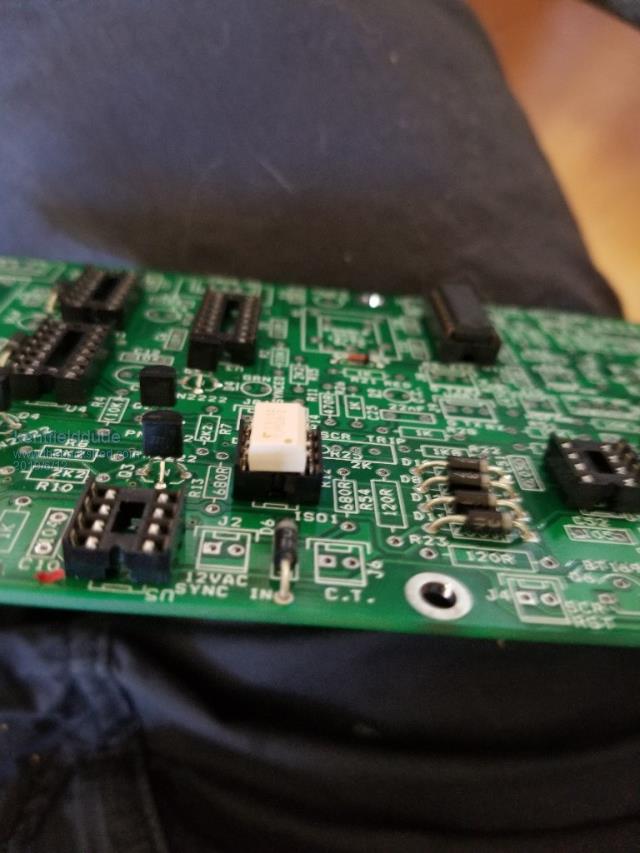 |
||||
| renewableMark Guru Joined: 09/12/2017 Location: AustraliaPosts: 1678 |
Mine had 4 pins, have you got a link or a better pic of the part? If you got the tlp523-2 that is a 2 channel, the top channel just wont get used. Here is some info on them. Cheers Caveman Mark Off grid eastern Melb |
||||
| poida Guru Joined: 02/02/2017 Location: AustraliaPosts: 1392 |
Just an update for nano2 code. I added LCD backlight support, for some I2C based 20 x 4 LCD parts based on the PCF8574 IC. I Improved the calibration of AC volts, AC amps, DC volts and DC amps by now taking 25,000 samples and using the average. Please note you can use an Android mobile phone and a USB OTG cable plus a free serial terminal app to communicate with the nanos. This means some of us no longer need to take the PC out to the shed to calibrate the nano2. This current version supports offset and gain for both AC amps and DC amps if you choose to use current sensors for either. 2019-07-03_230017_nano2_5_ac_current_sensor_dc_signal.ino.zip wronger than a phone book full of wrong phone numbers |
||||
| Madness Guru Joined: 08/10/2011 Location: AustraliaPosts: 2498 |
Hi Poida, Finally, I have read through all the posts on the Nanoverter, I see that you have no need yourself for generator syncing. Over the next few weeks I will get stuck into this, looks like I will need to redesign the Nanoverter drive PCB. From what I can see so far I will need to add AC current sensing for the generator input in order to control the generators maximum load. I will look at doing this by adjusting the Nanoverters AC voltage. Some other more basic stuff I want to add also includes generator auto start and shut down based on battery voltage and the time of day. The generator I am planning to use is a 10KW Onan Diesel. Also wondering if it is worth going to an STM32 rather than 2 Nanos. Is Gaspo still around if so have you made any progress with the STM32? There are only 10 types of people in the world: those who understand binary, and those who don't. |
||||
| poida Guru Joined: 02/02/2017 Location: AustraliaPosts: 1392 |
Mad, I would not consider changing over to the STM32. Firstly, there are marginal if any benefits from the point of view of the performance of the code when running. The Nano only uses about 20% of the cpu cycles to control the PWM output and run the closed loop output control. There remains approx. 80% of cpu cycles left unused. Memory use is moderate and no problem. The Nano runs in a way that is completely determinable, which I mean to say each interrupt of the 20kHz PWM routine occurs at about the exact same time it should. There is very little jitter, I estimate way less than 10ns. And this is running the Nano with the bootloader enabled, which permits easy uploading of the software. Secondly, the cost is not large, when choosing to use 2 nanos. They go for about $5 each, buy them in lots of 5 or so. This compares well with the STM32, which are also similarly cheap. Thirdly, I like very much separating the two functions of the control board into 2 microcontrollers. One just generates the PWM and runs a closed loop control. It also can alter the output sine wave frequency to sync up with an external source. The other interacts with the world and the humans. It can perform it's tasks in however long they may require. Updating LCD data can require appreciable amounts of non-interrupted time. I could not get smooth LCD updates when running it all on one cpu. The PWM interrupt upset aspects of the I2C communication codes. Fourthly, I have looked at the STM32 closely and I like a lot of it's features. The 32bit architecture appeals greatly. It has a lot of program memory and RAM. It runs at 72MHz, not 16Mhz as with the Nano. But there are aspects of the STM32 Blue pill board that are fiddly. Getting USB working, for easy programming was a pain, but it's possible and I have done it. Interrupts do not run as jitter free as the Nano, though. Below is a capture of the STM32, running an interrupt code that just pulses an output pin, at 20kHz. The capture is triggered on one pulse and in the lower screen shows all the occurrences of the following pulse. There is jitter in the interrupt service starting time of about +/- 1.5uS. If I did this with the Nano, we would see only one pulse, superimposed on itself, and my oscilloscope's performance is insufficient to discriminate anything much less than about 5nS. No point in showing that capture here. 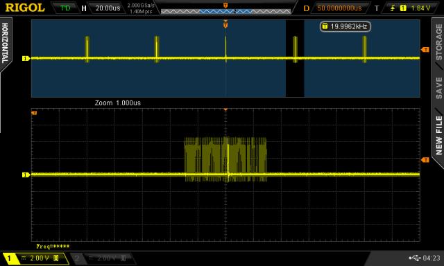 This jitter is the result of the STM32 running a bootloader that must poll the USB status registers even if the USB cable is not connected. Programming the STM32 can be done without a bootloader of course (that's how I managed to load the bootloader in the first case!) but it's a pain. Then you get much less jitter, down to the DSO's time resolution. The STM's 32bit timer counters are sex on wheels, I love them. So much more timer resolution compared with the Nano. And the RAM and program size... But in this application, the Nano brings highly predictable timing of it's events, and there are cpu cycles and memory to spare. All with a reliable bootloader. And 5V logic. No farting about to get the USB working either. The nanoverter board is completed and works fine. I just ordered another 10 boards and they are $6.70 AUS each, including postage. Add the 2 $5 Nanos etc. It's not a lot of money to make a good controller. I also looked at the ESP32 (the tiny board with onboard wifi) and it's interrupt jitter is a lot worse. There are some parts of it's firmware that interrupt the interrupt as it were. Not good for my purposes in this project. And every program has a minimum size of about 200kbyte. Bloatware. here is the STM32 interrupt code used in the above DSO test. HardwareTimer inverterTimer(4); #define SYSTICK_CTRL (uint32_t *)(0xe000e010) void setup() { pinMode(PB0,OUTPUT); pinMode(PB8,OUTPUT); inverterTimer.setMode(TIMER_CH4, TIMER_OUTPUT_COMPARE); inverterTimer.pause(); inverterTimer.setPrescaleFactor(1); inverterTimer.setCount(0); inverterTimer.setOverflow(3600); inverterTimer.setCompare(TIMER_CH4, 1); inverterTimer.attachCompare4Interrupt(timer_Handler); inverterTimer.refresh(); inverterTimer.resume(); //SysTick->CTRL = 0; works for Due, stops systick ints //*SYSTICK_CTRL = 0; //systick_init(1000); // writes my own systick count value, much faster "seconds" now } void timer_Handler() { gpio_write_bit(GPIOB, 0, HIGH); gpio_write_bit(GPIOB, 0, LOW); } void loop() { // this will show the latency of the interrupt. You will see about 1uS // before anything is executed in the interrupt code, then the int code runs // then another 1uS before this code here continues. // calling an interrupt costs 2uS of time where nothing can be done. gpio_write_bit(GPIOB, 8, HIGH); gpio_write_bit(GPIOB, 8, LOW); } wronger than a phone book full of wrong phone numbers |
||||
| Madness Guru Joined: 08/10/2011 Location: AustraliaPosts: 2498 |
Thanks Poida, I have some STM32's on the way but I can use them for other things. As for the ESP32 I would not be considering something that has the WIFI antenna onboard, too many problems with putting it in a metal box and having communications, far better to go ethernet or external antenna for me. Been through that with a 3D printer I built recently. From what I can see I am going to need to redesign the PCB to include AC current sensing from a generator. Plus I want to get rid of all the pointless IC sockets for all those MOSFET drivers that are not used. Have you made any progress with syncing and charging from an external AC source, my only reason for using the Nano board is to be able to charge from a generator. There are only 10 types of people in the world: those who understand binary, and those who don't. |
||||
| poida Guru Joined: 02/02/2017 Location: AustraliaPosts: 1392 |
No progress in mains sync. I know it does sync to a signal. I have tuned it's performance a good amount, with the changes I made that now use 10 bit fractional math when fine tuning the PWM output. There is less phase error when locked. I am thinking that maybe when it's locked, there is no changes to be made to PWM duty cycle. I see the likelihood of the nano control loop finding a higher output voltage than required, and so it reduces duty %, more and more until the volts drop. It could get to the stage where duty % is so small that we have a boost converter operating here. Taking the primary winding voltage and boosting it way, way up, past what the MOSFETS can handle. So when syncing up things, the inverter that's doing the slave role, taking an external sync signal should just stay put in duty cycle % whenever it's sync'd. The other device (generator, other inverter, street supply) would just keep doing what it does. dunno. Investigations. And sparks. Fuses to blow. The sync function is there mainly to kickstart a bit of investigation that I think we all would find interesting. Also, it's something that the EG8010 can not do, without external help that alters it's clock to obtain sync. Kind of bragging rights thing. The idea of backfeeding an inverter makes me mentally take a few steps backwards from the powers that are in effect here. I know some of us here do it with Grid Tie inverters. wronger than a phone book full of wrong phone numbers |
||||
| kentfielddude Regular Member Joined: 09/05/2019 Location: United StatesPosts: 89 |
Poida. Have you looked at the samd51 or samd21. The samd51 has floating point unit. Not sure if that will make a difference in this aplication |
||||
| poida Guru Joined: 02/02/2017 Location: AustraliaPosts: 1392 |
The poor ATMega 328p floating point speed is not an issue in any of my time critical code. The PWM interrupt code uses 16 and 32 bit integer math. It executes fast, taking about 10uS of the allowable 50uS of the 20kHz interrupt frequency. There is plenty of time to spare. The nano1 closed loop code uses floating point and it executes easily fast enough to complete in the needed time. The control loop is run at 100Hz, in testing I have had it run at 4kHz, using this spare cpu clocks left over from the 20kHz interrupt code. samd51 is $20 US from sparkfun. this is about $28 AUS 3.3V logic, 120MHz clock, hardware floating point, 1Mb of code space This is the sort of thing to drive a high performance quadcopter. wronger than a phone book full of wrong phone numbers |
||||
| Madness Guru Joined: 08/10/2011 Location: AustraliaPosts: 2498 |
Yes, you certainly have some bragging rights, to me syncing to a generator is the holy grail. My old trace inverter did it very well but it has lost it's smoke mainly due to old age, it was built last century. It was also capable of back feeding to the grid but was never approved for that in this country. Currently, I have a 2 GTIs connected and it runs perfectly, there is no downside to it at all that I am aware of. The only problem I have had is when I had a short to ground in my GTI regulator that caused the GTI to blow and it also took out the inverter. Since I have fixed that with better insulation there has not been one issue. My inverter is pushing 70 plus amps back into the battery everyday the sun is shining. Reading through your post Peter I found this "So, gen is running, with X AC volts. Inverter is running, with Y AC volts initially and ramps up or down PWM to make the now shared AC output = set point when you close the contact breaker. (not me...) Some load is on, no change, the gen can handle the output. Some more load is on, taking gen AC down, past inverter setpoint and so PWM is increased and AC voltage maintained. Heaps of load is on now, inverter is maxed nearly, not to extent of exceding DC current limit, and gen is doing it's bit. Meanwhile, the AC frequency has been bouncing around and about like a loon... " From what I understand is that once the generator is synced and connected to the output of the inverter the current flow can be regulated via the inverter voltage setting of the SPWM. I am assuming this is what happens when a GTI is producing more power than what is being consumed and my current inverter then feeds current to the battery. So by sensing the generator current and lowering the inverter volts to draw the set amount of current from the generator it should load down the generator to that point and hold it there. Then no matter what load is applied to the home power grid the inverter would adjust the voltage to maintain the generator current. There is other functions I would add such as disconnecting if the sync is < or > 3 HZ from 50hz, the load would also needs to ramp up over a few seconds so as to allow the generators governor time to respond. The old Trace inverter also could auto start/stop the generator depending the battery state of charge, this also had setting to prevent it starting at a bad time of the day. However there was a setting that would start the generator no matter what the time was. If anyone is interested you can read the manual for the Trace Inverter here on page 71 it gives quite a bit of detail about the settings etc for generator syncing. There are only 10 types of people in the world: those who understand binary, and those who don't. |
||||
mackoffgrid Guru Joined: 13/03/2017 Location: AustraliaPosts: 460 |
Poida, totally agree with not changing from the Nano. There seems to be a number of users of nano-Ozinverter out there, So.... If it's not Broke don't fix it. I have used the Nano in a number of real world applications where its testing its resilience, ie water pump controller, fridge controller, in a tractor, all places where relays are actuating and decent currents are being switched. No problems at all. My Stm32 experience is new. I Don't Use the USB bootloader on the stm32, too much of a pain, I'm happy just to use the serial uploader. The extra benifits of its architecture are enticing as you mentioned. I really like the Dual ADC and particularly that's its 12bit. I wish the Nano / Atmega 's ADC was 12 bit. I would equally agree if someone wanted to try the stm32 in a pwm-inverter for some reason - just forget the USB bootloader. |
||||
| renewableMark Guru Joined: 09/12/2017 Location: AustraliaPosts: 1678 |
That's interesting actually, who else is using one to run their house? Cheers Caveman Mark Off grid eastern Melb |
||||
| Madness Guru Joined: 08/10/2011 Location: AustraliaPosts: 2498 |
Looks like you are Robinson Crusoe. There are only 10 types of people in the world: those who understand binary, and those who don't. |
||||
