Notice. New forum software under development. It's going to miss a few functions and look a bit ugly for a while, but I'm working on it full time now as the old forum was too unstable. Couple days, all good. If you notice any issues, please contact me.
BenandAmber Guru Joined: 16/02/2019 Location: United StatesPosts: 961
Posted: 11:48pm 25 Mar 2019
Copy link to clipboard
Print this post
Okay guys and girls I'm going over everything again before first start up Thanks to poida patience and wisdom
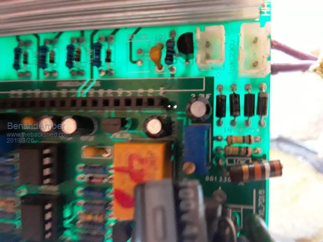
This is the fix I did for the 220 to 110 The trimpot is 10K the resistor I changed out was a 10k I replaced it with funny Brown looking one it is a 40k Still haven't got my head wrapped around the math involved
I removed ESGoo2 and plugged the 2 purple voltage feedback wires into a 110 outlet so I could change out resistor and check voltage on pin 15 vfb isn't that a genius idea not mine of course poida Mastermind behind that
I did as I was told by poida earlier in post and removed 393 chip soldered c-19 I also shorted out jp1 for 60 Hertz hope I got everything right if not please comment my question is with the way poida had me do it do I still need to short 7 to 8 and jumper from1 to 4 and does the on and off switch still work ???
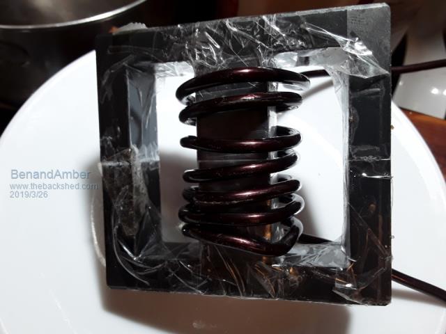
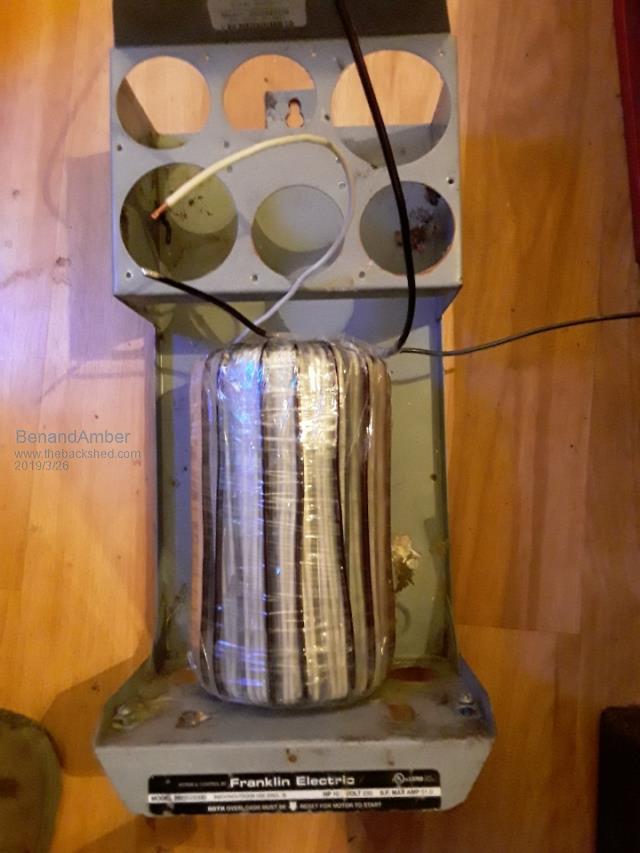
This is a e70 it is made of 87 ferrite 50.7 uh
This is the Transformer Amber wound and the Box she's putting it in
Edited by BenandAmber 2019-03-27be warned i am good parrot but Dumber than a box of rocks
poida Guru Joined: 02/02/2017 Location: AustraliaPosts: 1392
Posted: 02:50am 26 Mar 2019
Copy link to clipboard
Print this post
I forgot to tell you about the 50 and 60Hz selection you needed to make. Sorry.
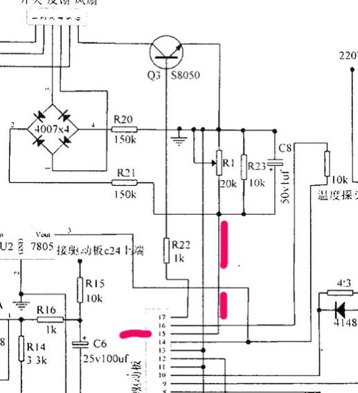
there is no jumper for 120V or 240V. The output voltage is set by you giving 2.5V DC at the Vfb pin at the required AC output voltage.
On the inverter board you have, the AC output is first sent through a bridge rectifier, then 2 x 150K Ohm resistors to reduce the current, then this current goes to two resistors in parallel. One is 10K, one is a 20K trimpot.
The trimpot has enough adjustment range to allow you to choose to run the inverter at 240V or 120V, when feeding the AC (240V or 120V) directly into the bridge rectifier via the small 2 pin connector.
There is no need to change anything on the board, if you want to use the AC output direct from the toriod.
That is one way to provide voltage feedback.
Another way to provide voltage feedback is to make the 2.5V DC yourself. I think you have already a 6V transformer, with a 120V primary. OK, rectify and smooth this 6V AC, (one diode, maybe a 10uF 25V cap) and take this DC and put it across a 2K trimpot. Get your 2.5V DC from that and feed it directly into Vfb, bypassing the diode bridge, resistor, etc. Right up to the pin on the board. Of course you need to bring the ground wire onto the board too. Remove the smoothing capacitor 4.7uF 50V you have in the drawing you made. This will make the voltage change too slowly, in my view. It might work? Dunno.
This will help us all understand what is going on. It's the circuit of the Vfb part of most of these inverter boards.
wronger than a phone book full of wrong phone numbers
poida Guru Joined: 02/02/2017 Location: AustraliaPosts: 1392
Posted: 03:04am 26 Mar 2019
Copy link to clipboard
Print this post
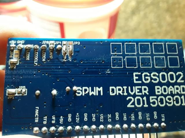
I think the jumpers on the back of the EGS002 are good to go. 60Hz is set by jp1 - done soft start is set by jp2 - done the dead time is nearly always OK.It is set on your board to 300uS, the quickest. jp7 and jp8 No problems with the shortest dead time.
So if you have shown that the Vfb trimpot is set to give 2.5V at Vfb pin, when you feed the AC feedback wires 120V, then I think you can hook it up now.
If you have a bench power supply, I would use it to give maybe 50V and set the current limit to 1 amp. IF no bench supply, no problems, just use what you got.
You might need to solder up a simple on/off switch and plug that in the appropriate spot. It wont work unless you close the switch. ...and then we have to deal with the under and over DC voltage limit settings. But it should work at 50V if it's a "48V" unit. wronger than a phone book full of wrong phone numbers
wiseguy Guru Joined: 21/06/2018 Location: AustraliaPosts: 1017
Posted: 03:23am 26 Mar 2019
Copy link to clipboard
Print this post
I believe that any voltage below 2.75V or above 3.15V will bring up the Vlo/Vhi error. I think 3.0V is the usual setting.
Still concerned about the shown transorb connections - I predict a good possibility of 2 x dead FETs and 2 x dead IR2110s.
Simple way to prove it, measure from the Batt + connection to the anodes (no band at the end) of the 2 green wire transorbs if it measures shorted I suggest you fix it.If at first you dont succeed, I suggest you avoid sky diving.... Cheers Mike
BenandAmber Guru Joined: 16/02/2019 Location: United StatesPosts: 961
Posted: 03:27am 26 Mar 2019
Copy link to clipboard
Print this post
That trimpot is 10K not 20K on my board tested it the resistor is 10k voltage from wall last night was 121 volt I ran wall outlet voltage to vfb on board purple wires and turn the trim pot all the way counterclockwise all the way clockwise
the highest voltage I could get I think was 1.7 volt so I pulled the 10K resistor out and put in a 3k and this went the wrong way the highest I could get then was 0.7 volts then tried a 18k and the most voltage I can get was 2.1 volt then I put a 24k the highest was 2.4 then I put a 40k and adjusted the 10K trimpot until I got 2.56 volts 2 pin 15 vfb but the trimpot is most definitely 10K and the original resistor was 10k out of circuit also the numbers on top of the 10K trimpot is w 103 be warned i am good parrot but Dumber than a box of rocks
BenandAmber Guru Joined: 16/02/2019 Location: United StatesPosts: 961
Posted: 03:55am 26 Mar 2019
Copy link to clipboard
Print this post
Good news good news good news I tried the little inverter board out this evening I probably shouldn't have because I am still at waiting on DC Breakers but I said what the heck and put a 30 amp automobile style fuse in line from battery hot lead
I didn't realize a car fuse could blow so loud as soon as it blew dummy me grabs it and pulled the Spade connector off of course it fell down on the negative screw on the input side
now that was some fireworks it either blew the 2ho and 2lo mosfet before or after Spade incident I think it was before when the 30 amp fuse popped the board sat there and ran fine before I turn the on switch on the red light on the board was lit up
everything seem to be fine before I turned it on so I don't know if the Transformer is the problem or voltage feedback where I put the 40 K resistor in or if the mosfets were faulty to begin with they were four different mosfets but had same model numbers
I'm thinking about using a little 250 VA Transformer like the ones I sent ladyN I have more of them they have a hundred and twenty volt winding so I could just wind a 32-volt primary
I will be replacing all for mosfets with Hy 4008 I ordered a hundred of them but they haven't came in yet
I would appreciate any comments if anybody thanks they might know what blew it up I'm thinking maybe the Transformer or I could have done the voltage feedback wrong but I don't see how because I plugged it into the wall outlet and I set it to 2.56
I just don't know
Thanks for all the help so far I'm afraid I might need a little bit more by the way I never give up
I fake it till I make it
I think more of that magic smoke I hear you guys talking about might have to escape
Peace good health and happiness to allbe warned i am good parrot but Dumber than a box of rocks
BenandAmber Guru Joined: 16/02/2019 Location: United StatesPosts: 961
Posted: 04:03am 26 Mar 2019
Copy link to clipboard
Print this post
I recorded the event but it's not very spectacular Amber turn the camera off before I drop the Spade connector so the big firework show is not on the video
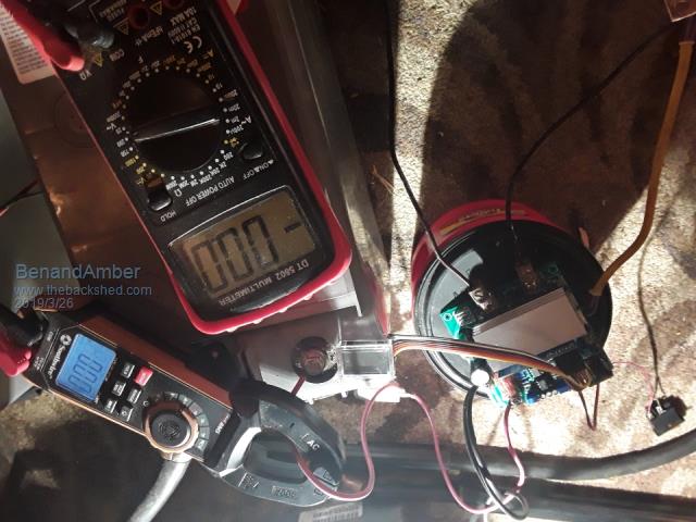
I had an amp clamp on the DC input and a multiple meter on the 120 volt output I'm going to look back through it and see if that tells me something
While I'm waiting on the mosfets and other parts I think I might try to build the little circuit that gets all the AC off the inverter board like poida was referring to
I am in this for the long run I absolutely loved Electronics when I was a kid did a bunch of messing up didn't get to pursue it but now I can
Thanks again for your timeEdited by BenandAmber 2019-03-27be warned i am good parrot but Dumber than a box of rocks
renewableMark Guru Joined: 09/12/2017 Location: AustraliaPosts: 1678
Posted: 04:13am 26 Mar 2019
Copy link to clipboard
Print this post
Welcome to the club, you blew something up.
At least it's not a full 6kw board of fets, good little board for you to learn from. You might want to get a few of the egs boards, that one is likely fried now.
You'll need a scope to check it.Cheers Caveman Mark Off grid eastern Melb
BenandAmber Guru Joined: 16/02/2019 Location: United StatesPosts: 961
Posted: 04:38am 26 Mar 2019
Copy link to clipboard
Print this post
I know it was so much fun even though it only lasted a Split Second 😁😆😁 Looks like over 190 amps for that nanosecond it was all worth it the video is short but I tell Amber to step back it might blow up as soon as she stepped back I flipped the switch and it pop it scared her and she made the funniest noise too bad you can't put a video on here you guys will get a kick out of itEdited by BenandAmber 2019-03-27be warned i am good parrot but Dumber than a box of rocks
wiseguy Guru Joined: 21/06/2018 Location: AustraliaPosts: 1017
Posted: 05:49am 26 Mar 2019
Copy link to clipboard
Print this post
Yes just look a few posts ago but it appears to have been ignored.
Along with Poidas suggestion of a current limited supply.
My 2 x dead FETs prediction was assuming you followed Poidas advice and used the current limited supply - I now suspect more damage than originally suggested.Edited by wiseguy 2019-03-27If at first you dont succeed, I suggest you avoid sky diving.... Cheers Mike
poida Guru Joined: 02/02/2017 Location: AustraliaPosts: 1392
Posted: 07:42am 26 Mar 2019
Copy link to clipboard
Print this post
OH no. I feel I have most responsibility for this one. I don't know how I did it, 4000 miles away, but I did it!
I think the problem was the TVS diodes. For a start, I should have told you not use them in this small test inverter. You won't need them, and it's just a complication we can avoid.
After your test, and finally had a close look at how you installed them. I think you didn't do it right. Wiseguy pointed this out too. I've been on and off the forum and so I can't give enough time to fully oversee your actions.
The wiring for the TVS is to have the end with the band connected to the MOSFET gate or even better, at the gate drive before the gate resistors and diode. The other end (no band) needs to go to the same MOSFET's source pin.
MOSFETs have the pins arranged in order from left to right, when looking at the side with part markings, gate, drain, source.
The idea is to stop the gate voltage going lower than about a diode drop (negative) compared to the source pin. And to prevent the gate going higher than 20V, which is the maximum allowed by the manufacturer.
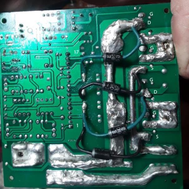
The photo you posted:
shows to me that you got 2 of them wrong, when I look at the TVS terminating at 2 FET's drains. This is not good. You got the banded ends right. Again, I wish I did not permit you to fit these, on a little test board. wronger than a phone book full of wrong phone numbers
LadyN Guru Joined: 26/01/2019 Location: United StatesPosts: 408
Posted: 05:52pm 26 Mar 2019
Copy link to clipboard
Print this post
OK, so please let me know if I am wrong:
1. in theory, setting Vgs to GND should turn off the FET 2. In reality, it takes a while to drain Cgs, so to expedite the discharge process, engineers sometimes set Vgs to -0.7 (WHY? -0.7. Why not say -Vgs_max?) 3. At all times we must be midful not to exceed Vgs_max. To ensure this a zener rated Vgs_max might be useful but zeners are not as fast as TVS diodes, so if possible to source a TVS with Vgs_max, prefer that over a zener
Did I get all of them right?
BenandAmber Guru Joined: 16/02/2019 Location: United StatesPosts: 961
Posted: 07:34pm 26 Mar 2019
Copy link to clipboard
Print this post
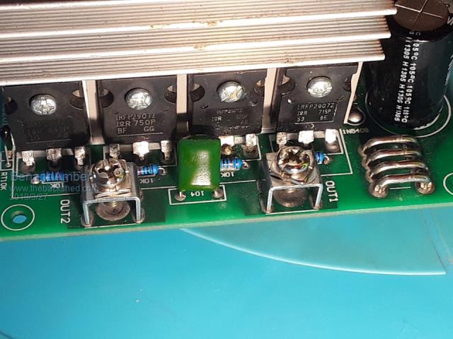
TVS is right the big thick solder at the very top that you got marked D for drain is the source follow it down to the bottom of the board and to the left see a gap and then another big solder that's the fuses
that is the source where the the positive comes in
none of you guys have this board in your hand where you can turn it around in circles and check it out with your multimeter therefore it's impossible for anyone to know all about it
POIDA the grate put pics of his board up to help explain things so I looked on his board and tracked it back and I put my TV s before the resistors like he did
I honestly think that only two mosfets are burnt I've checked everything out the best I know how I have a hundred Hy 4008 coming
Lots more fun lots more mosfets must die like some of you guys say Picture Tells a thousand words and I should have put more detailed ones on here
was bought for our learning experience and I'm learning a lot and I appreciate everyone's help so please don't turn into something bad because it's very good everyone that gave me advice have told me why they gave me that advice they didn't just assume that they got the layout perfect they told me the reasons why they thought I should do this that away or the other
the big u-shaped sodders you see at the top are the output of this little board here's a pic be warned i am good parrot but Dumber than a box of rocks
BenandAmber Guru Joined: 16/02/2019 Location: United StatesPosts: 961
Posted: 07:37pm 26 Mar 2019
Copy link to clipboard
Print this post
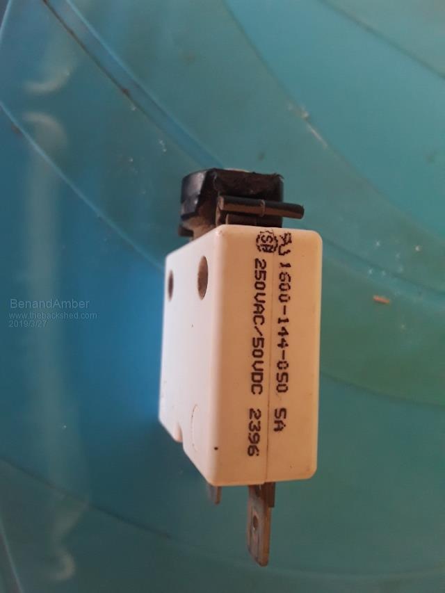
The very first try I used a little pop out DC fuse The fuse is very weak it popped out as soon as I touched the power cable to the battery
immediately pushed it back in and continue to bolt down battery cable the little red light on the board was on and it was doing fine I then hit the switch to turn the inverter on
little fuse popped out at this point I figured the inrush current to the big toroid was too much for the week 5 amp fuse on the input so I immediately put the 30 amp car fuse in there the little red light was still being powered by the capacitors with battery cable off
I got the 30 amp fuse back in there before the little red light went all the way out hit the switch again poof it blew up the 30 amp fuse I went over things again and again and again checked everything with my multimeter again and again and again
I really don't think that I done anything wrong i could be very wrong as far as the alterations to the board I think I did no wrong What I think it maybe is not let the capacitors go to zero before I tried to start it again I really honestly think that that's the problem we will see when I get the hy4008
Thiswas meant for a learning experience we both learn a lot better by doing instead of reading
we both have learned so much and really appreciate you guys please don't give up on us
Peace good health and happiness to all Edited by BenandAmber 2019-03-28be warned i am good parrot but Dumber than a box of rocks
BenandAmber Guru Joined: 16/02/2019 Location: United StatesPosts: 961
Posted: 08:27pm 26 Mar 2019
Copy link to clipboard
Print this post
When the hy4008 come in I will have a 250 VA Transformer wound this time so inrush current won't be so bad
I will also have the correct DC breaker
this has been a life-changing event for the both of us this was my passion when I was a little kid
I truly and honestly appreciate every one of you guys that have commented every comment helps me and Amber to learn and I truly think God for this site and for your guys's help. we won't give up
I truly appreciate the valuable time that gets spent on somebody 4000 miles away that you'll probably never see
I truly believe what goes around comes around and you guys got a lot of good coming back your waybe warned i am good parrot but Dumber than a box of rocks
renewableMark Guru Joined: 09/12/2017 Location: AustraliaPosts: 1678
Posted: 09:08pm 26 Mar 2019
Copy link to clipboard
Print this post
You'll need a scope mate, start looking for a decent second hand one.Cheers Caveman Mark Off grid eastern Melb
wiseguy Guru Joined: 21/06/2018 Location: AustraliaPosts: 1017
Posted: 12:38am 27 Mar 2019
Copy link to clipboard
Print this post
Not sure if I'm addressing Ben or Amber but I feel the need to give you a short reality check which I hope wont offend. As you have rightly gathered there are some very talented people on this site and as yet you guys are not there and still a work in progress.
I am confident that you are quite aware of some that have been trying to be helpful and already gathered some are more helpful than others, but if you decide everyone is wrong and that you believe what you have done is right, you better order a lot more than 100 Mosfets. You will also find that if you ignore the "experts" they will begin to ignore you which is not what you need on this learning curve.
The source of Positive energy connects to the Drain of an N Channel Mosfet you are confusing your terminology, dont think source for energy think "+" or "-". When using Mosfets, reserve the names Source Drain and Gate for the 3 connections. The Centre is the Drain not the Source.
Some of us dont need to hold a PCB in our hands to "know about it". I have lived and breathed electronics for over 50 years and have been designing PCB's for over 40. I can usually read a power PCB from the track side like a blind person reads braille & there are others on this site that can do likewise. It is actually possible for us to know enough about it to see a glaring error without needing to have it in our hands. Most of us have made similar errors to the ones on your PCB on our learning curve.
Those output connections are the Drain of the lower mosfet and the Source of the upper mosfet
The upper Mosfet should have the (green wired anode)connected to the upper Mosfets source connection, which is an outer connection and as Poida has correctly drawn (Dont worry that is is also connected to the lower FET's drain). Edited by wiseguy 2019-03-28If at first you dont succeed, I suggest you avoid sky diving.... Cheers Mike
wiseguy Guru Joined: 21/06/2018 Location: AustraliaPosts: 1017
Posted: 12:59am 27 Mar 2019
Copy link to clipboard
Print this post
Your first hint that there may be a problem.
Your second hint
Your 3d hint (note also the control board was (should be) wired for soft start so inrush should not be the issue.
When you get better at electronics you begin to take notice of "hints". The first thing is always assume "what have I done wrong" as that is usually the cause. If you just replace the Mosfets without considering you perhaps did make a mistake or havent learned to listen you are in for a rough ride. Listen to good advice, dont go off with too many creative theories - you get to do that more effectively once you have a few runs under your belt.Edited by wiseguy 2019-03-28If at first you dont succeed, I suggest you avoid sky diving.... Cheers Mike
BenandAmber Guru Joined: 16/02/2019 Location: United StatesPosts: 961
Posted: 08:39am 27 Mar 2019
Copy link to clipboard
Print this post
Okay I am really confused all the comments I wrote earlier sound horrible when I read them back
I sound like the most arrogant ignorant a hole in the world this is not the way I meant it to sound the only thing I was trying to convey earlier was poida and everyone else on here gave good advice and didnt do anything wrong
I was truly trying to put the blame back on me but it sure don't sound like that when I read it back
I'm very sorry to everyone that I might have offended my intentions we're truly good
I hope eveyone accepts my apology be warned i am good parrot but Dumber than a box of rocks
BenandAmber Guru Joined: 16/02/2019 Location: United StatesPosts: 961
Posted: 08:42am 27 Mar 2019
Copy link to clipboard
Print this post
All blame belongs to me Ben and no one els
Thanks for all the helpEdited by BenandAmber 2019-03-28be warned i am good parrot but Dumber than a box of rocks