
|
|
Forum Index : Electronics : Little China inverter board came in today
| Author | Message | ||||
renewableMark Guru Joined: 09/12/2017 Location: AustraliaPosts: 1678 |
Be careful with hairdryers and heat guns, they may use the copping of wave method for low settings. Look here Cheers Caveman Mark Off grid eastern Melb |
||||
| BenandAmber Guru Joined: 16/02/2019 Location: United StatesPosts: 961 |
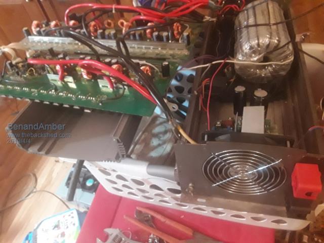 we found a nice case for our little inverter notice we put some big caps in Had to drill through the board and put 14 gauge wire up through works great The donor is a 12 volt inverter we used in the RV to run a air conditioner I was always impressed with this inverter it ran anything I plugged into it Worked fine when I took it apart But it had to go to make room or the low frequency Have you guys ever seen a inverter like that with all the little toroids instead of square Transformers Thanks for the tip renewableMark I'm going to go read up about that right now went and read the link my wife's hair dryer didn't affect the little inverter at all ran just fine my heat gun is a genuine Chinese didn't affect it either I noticed my big circle saw would draw about 23 amps when it first kicked on just for a second though be warned i am good parrot but Dumber than a box of rocks |
||||
| BenandAmber Guru Joined: 16/02/2019 Location: United StatesPosts: 961 |
Still very happy with the little inverter the only complaint I have is the choke is loud it's an e80 with a gap Just was running my big circle saw with it the other day drawing 23 amps for a Split Second and 14 and 15 amps for long periods idle current is .37 amps after a few modifications For something that cost under $30 and a bunch of parts I had laying around can't beat that with a stick be warned i am good parrot but Dumber than a box of rocks |
||||
| renewableMark Guru Joined: 09/12/2017 Location: AustraliaPosts: 1678 |
Well done Ben, you have a working machine. Have you got some pics of how the choke is mounted? Cheers Caveman Mark Off grid eastern Melb |
||||
LadyN Guru Joined: 26/01/2019 Location: United StatesPosts: 408 |
A true inspiration. Would it be possible for you to upload a video (with audio) of the little inverter with nothing running at first (to hear the idle noise) and then with a heavy load you are comfortable with (like a hair dryer) and then go near the inverter again to hear the noise under load? |
||||
| BenandAmber Guru Joined: 16/02/2019 Location: United StatesPosts: 961 |
Don't mind to do that at all you just have to let me know where to upload a video to and you might have to give me instructions on how to do it It's not a deal-breaker or anything I mean it's just a little bit loud if you had it right beside of you and you is trying to watch TV late at night or something you know it might be a problem if you had it in another room it's not loud enough to be a problem it is quite a bit louder than the case fan but you know I could have done something wrong on this ladyN On my big inverter I used clear Auto Body fiberglass resin and encapsulated the whole thing so I'm thinking it won't be loud at all be warned i am good parrot but Dumber than a box of rocks |
||||
| LadyN Guru Joined: 26/01/2019 Location: United StatesPosts: 408 |
You could just upload to youtube and mark the video as private so that only those of us with a link to it can see it. There are other sites like mega that also allow you to upload video files but youtube makes it very easy |
||||
| BenandAmber Guru Joined: 16/02/2019 Location: United StatesPosts: 961 |
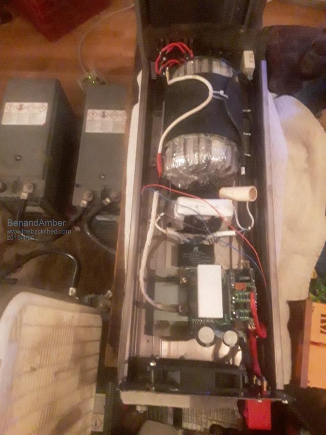 Renewablemark It is white and it is in the very center it has quarter inch rubber underneath of it and the white is made out of flexible water pipe split open and cupped around the e80 core 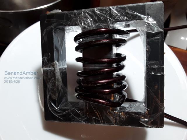 Pretty poor excuse for a choke if you want to go off your work and a lot of the other excellent awesome people on here but I'm just a newbie and very poor so poor people have four ways By the way it came with no Gap and I made the center Gap myself so that could have something to do with how loud it is it is glued together on the outside legs Hey if this core was three times as loud I would still be really impressed I would encourage anyone else that wants a really powerful inverter cheap to follow what poida the great wrote to me earlier in this post Thank you for taking the time to read my post and be interested in it be warned i am good parrot but Dumber than a box of rocks |
||||
| renewableMark Guru Joined: 09/12/2017 Location: AustraliaPosts: 1678 |
If you look towards the bottom of this page you can see how to clamp them so they don't squeal. Otherwise you can superglue them (with the spacers) Be very careful if clamping, ferrite is incredibly brittle and will crack if you just look at it the wrong way. Glue is safer but it's permanent, no changes easily then. Cheers Caveman Mark Off grid eastern Melb |
||||
| brucedownunder2 Guru Joined: 14/09/2005 Location: AustraliaPosts: 1548 |
If its a help or consolation, When I used my heat gun (hair dryer) on my powerstarW7 or my Torodial modification to the W7 , it made a fairly disturbing rattling noise. I purposely kept it working on the heat shrink job ,but no problems. She returned to normal under ordinary loads and rattled and hummed when the Ol hairdryer was on , Bruce Bushboy |
||||
| BenandAmber Guru Joined: 16/02/2019 Location: United StatesPosts: 961 |
Mine doesn't get any louder with load just constant humming and the two outer legs are super glued together the center has a gap the capacitors I ordered for this little tiny inverter came in and I put them in this evening 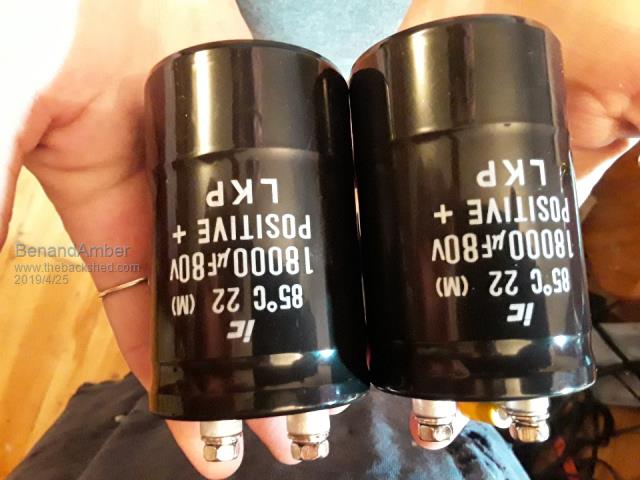 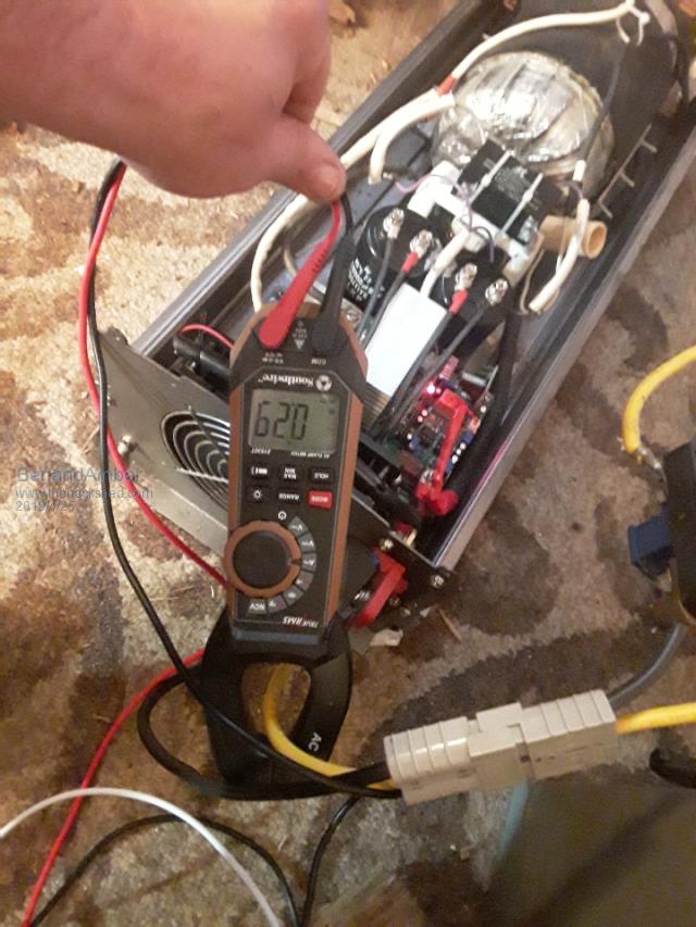 I'm happy with that idle current that big case fan is running constantly never goes off I put the top on it testing over off to the RV to run all the power tools and a small air conditioner Just to remind everyone it has four mosfets that's it be warned i am good parrot but Dumber than a box of rocks |
||||
| BenandAmber Guru Joined: 16/02/2019 Location: United StatesPosts: 961 |
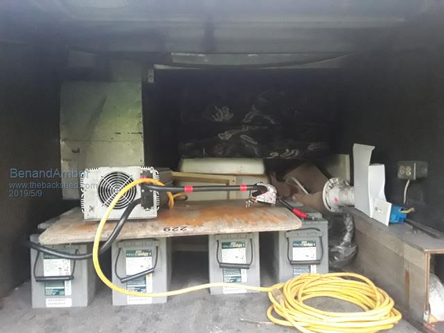 By the way the humming of the choke isn't bad at all with the lid on it I mean if you was using it for a pillow it might bother you but other than that it's great Still use it everyday at the RV under construction circle saw jigsaw sawzalls air conditioner and lights A special thanks to Poida the great be warned i am good parrot but Dumber than a box of rocks |
||||
| BenandAmber Guru Joined: 16/02/2019 Location: United StatesPosts: 961 |
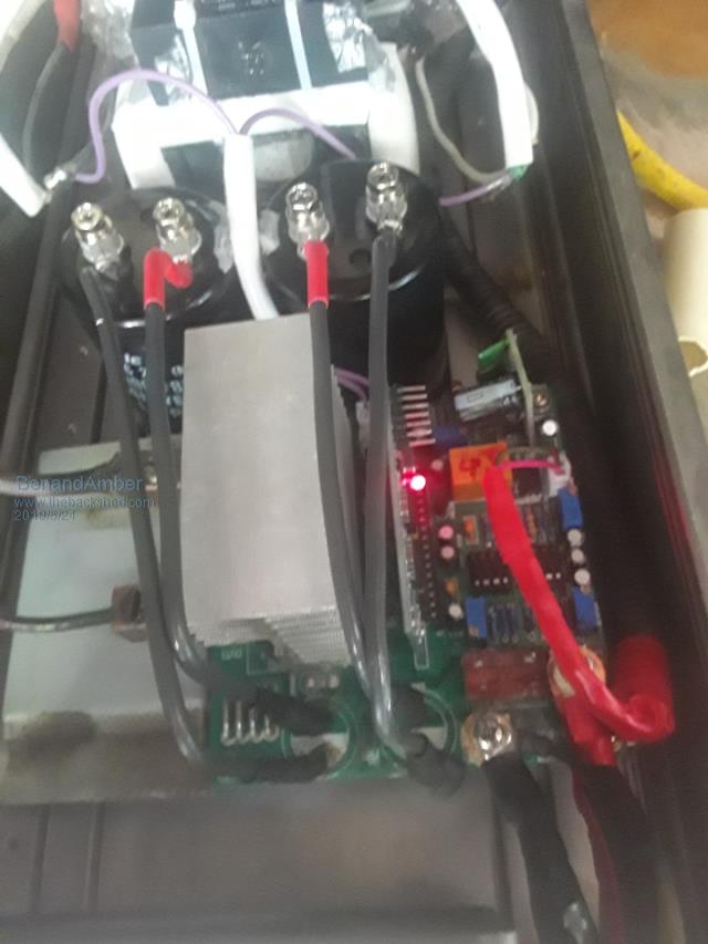 First break down on the little inverter When I would try to start my circle saw had a few other things running couple box fans lights radio it would kick off then kick right back on I knew instantly what it was aluminum wire The only suitable wire I had for winding my choke at the time was aluminum I knew better because I didn't have special solder to solder to aluminum So I used a big screw down connector and I used anti oxidation compound Didn't work I took the inverter apart as you can see and that's exactly what it was If you look hard in the picture above to the right of the choke you will see this connector I would advise anyone not to use aluminum wire it's burnt a lot of houses down because of the connections Back up and running for now but you never know about that aluminum wire it might be a day or week or month or I might even burn My RV down with the silly stuff Unless you can make really good soldered aluminum connections I would not even consider aluminum not even in a pinch just wait to get some copper wire As soon as I get time I'm taking it back apart and rewinding the choke be warned i am good parrot but Dumber than a box of rocks |
||||
| BenandAmber Guru Joined: 16/02/2019 Location: United StatesPosts: 961 |
I just seen your text ladyN The big high speed case fan is louder than the hum of the choke with the top on it is not very noticeable The mosfets do not even get warm most of the time unless I am running ac fans lights and power tools at same time I dont know how to up load a video I will try to figure it out or maybe have my son upload it to his YouTube be warned i am good parrot but Dumber than a box of rocks |
||||
| Tinker Guru Joined: 07/11/2007 Location: AustraliaPosts: 1904 |
Ben, when I saw that picture of your choke you posted last month I "knew' it was going to be noisy  . .Why don't you do you "monkey see, monkey do" thing and wind the choke with welding cable? One meter (3 feet) should do. That works for others and I think you are still too close to the inverter modifying starting block to do something radically different. A few observations: the winding needs to be physically *very* tight around the center core and locked in the winding space. 3 turns of welding cable of the right diameter does that automatically. If you want to wind them like you saw in my pictures, I do that on a lathe, can't be done by hand winding. Your idea of removing part of the center leg to create an air gap was short sighted. Yes, it does create a gap but it also weakens that part so you can no longer apply sufficient clamping pressure to stop the buzzing noise. It would be much more clever to place a non metallic shim (strong card board, plastic, etc) between *all* three legs. No removing of any ferrite. This *must* be of exactly the same thickness at all legs or clamping pressure will crack the ferrite. The total 'gap' is now twice the thickness of one shim. You do that 'air' gap to increase the saturation level but without saturation testing gear its a stab in the dark and probably not worth the trouble. I ran a E65 ferrite choke for a long time in my first inverter, a power jack 8Kw module. That only had thin mylar tape (~0.1mm) between each leg. It reduced the humming and the inverter worked fine. In case you are wondering where the buzzing noise comes from, the very powerful alternating magnetic field in the core tries to move the wires and the core halves. If loose, they will get noisy. Klaus |
||||
| Tinker Guru Joined: 07/11/2007 Location: AustraliaPosts: 1904 |
And another observation on the picture above. I see you replaced the capacitors. Why do you think the original ones were soldered on the PCB? They were to make the shortest path for the heavy currents from the caps to the mosfets. Placing the caps on the opposite of the board and connecting them with long smallish wire just about negates what you tried to do. Place the bigger caps next to where the were originally located and connect them with tinned copper strips to the board, that is easier than making short big wire links with lugs on the end. Klaus |
||||
| Solar Mike Guru Joined: 08/02/2015 Location: New ZealandPosts: 1125 |
Using Al wire can be quite reliable, takes a couple of extra steps; the only reliable connection is a high pressure crimped joint eg to copper lug. 1: clean the wire with a stainless steel wire brush, one that hasn't been used on anything except aluminium, otherwise the wire gets contaminated. 2: apply jointing compound designed for Al wire. 3: crimp to your copper lug, soldering in any form isn't reliable and will fail with time. The high power electrical industry uses copper to Al joints all the time, no problems. Cheers Mike |
||||
| BenandAmber Guru Joined: 16/02/2019 Location: United StatesPosts: 961 |
I agree 100% the anti oxidation compound is code here where I live for the aluminum wire every two hundred amp meter base I've ever put in except for in commercial buildings has been aluminum and I've had no problems I have a copper screw down lug pretty similar to what is in a breaker box and I put the antioxidant Compound on it and still have problems I will check out those crimp connectors you're talkin about but I have to change this aluminum wire anyway it was only supposed to be temporary just like tinker was saying in the previous post I should have never been done like that to begin with I glued the choke together only filed a gap in the center post The wire and that Center Post is probably acting like a tuning fork just like tinker saying earlier I am very happy with this little inverter Thanks to poida the great I have a very tough little inverter to work on my RV and stay cool at same time as soon as I get another one up and running I'll be taking the little thing apart and redoing the choke and maybe move those capacitors I have them on I think 10 gauge solid wire I drilled down through the board and they are soldered onto the DC rails be warned i am good parrot but Dumber than a box of rocks |
||||
| Solar Mike Guru Joined: 08/02/2015 Location: New ZealandPosts: 1125 |
I would leave the original electro's on the pcb, if you want to add extra capacity as you have done - which is ok, then mount the extras closer to the pcb and wire to the underside of the pcb to the original electro terminals (thick copper braid works well for this). The pcb mounted ones should not be removed as they present a very low esr impedance with low connecting wire inductance. By removing them and placing at the end of long wires the circuit inductance will prevent them doing their job properly. Cheers Mike |
||||
| Solar Mike Guru Joined: 08/02/2015 Location: New ZealandPosts: 1125 |
Those copper screw down terminals would be pretty hopeless with AL cable, the point of contact is too small and air can still get into the joint.... the AL oxide that forms is an insulator so eventually the thing goes high resistance and (smoke)... Crimping by nature excludes air from getting into the joint and displaces any extra joint compound from between the two surfaces - jointing compound is also an insulator. Cheers Mike |
||||
