Notice. New forum software under development. It's going to miss a few functions and look a bit ugly for a while, but I'm working on it full time now as the old forum was too unstable. Couple days, all good. If you notice any issues, please contact me.
BenandAmber Guru Joined: 16/02/2019 Location: United StatesPosts: 961
Posted: 09:44am 27 Mar 2019
Copy link to clipboard
Print this post
Wise guy called it and tried to warn me on page 3 and 4 and his prediction was right two dead fets He already knew what I had done wrong before I done it
I should have paid attention to his post I missed it or arrogantly overlooked it I hope you will forgive me and overlook my ignorance
I'll try not to make the same mistake again!!!
I probably missed more so I think I should go back through and reread all the post might save me some trouble in the future
You can lead a donkey to water
thanks for all your helpEdited by BenandAmber 2019-03-28be warned i am good parrot but Dumber than a box of rocks
renewableMark Guru Joined: 09/12/2017 Location: AustraliaPosts: 1678
Posted: 10:56am 27 Mar 2019
Copy link to clipboard
Print this post
One REALLY important lesson Madness taught me was to not fit the power board caps , or in your case with a pre made board remove the caps. And feed the machine with a restricted power supply. This keeps the amps nice and low so not to cause a pop like you experienced. Running in this mode will not allow you to run any kind of load, but it will show you if it has a bad sine. Of course you need to observe this with a scope.
Hopefully your new powerjack will cover your needs for your motorhome, if it does, keep it simple, don't overload it and tinker with your little board in the mean time.Cheers Caveman Mark Off grid eastern Melb
wiseguy Guru Joined: 21/06/2018 Location: AustraliaPosts: 1017
Posted: 11:32am 27 Mar 2019
Copy link to clipboard
Print this post
Some like to post because they like to stir the pot. Some seek advice. Maybe some are lonely or bored. Some like to help. Some are so busy that they dont really have time to help.
Its the latter types that probably have shorter fuses if they take the time to write and then seem to get ignored for their trouble. You just need a real good filter to figure out whose is posting reasonable advice that you might want to follow - luckily there are quite a few of those types here.
No harm done dust your self off. Find some more Mosfets and dont let the bastard beat you - at least not until you run out of FETs ! Ive wondered about an ammo clip type FET replacer that can rattle em in faster than you can see, spitting out the dead ones at the same time - or you can try to see what else might be wrong. cheers !If at first you dont succeed, I suggest you avoid sky diving.... Cheers Mike
BenandAmber Guru Joined: 16/02/2019 Location: United StatesPosts: 961
Posted: 05:09pm 27 Mar 2019
Copy link to clipboard
Print this post
Monkey see monkey do If I see or read a really good idea and I can afford it I jump on it Apparently these will come in really handy for meEdited by BenandAmber 2019-03-29be warned i am good parrot but Dumber than a box of rocks
BenandAmber Guru Joined: 16/02/2019 Location: United StatesPosts: 961
Posted: 10:35pm 27 Mar 2019
Copy link to clipboard
Print this post
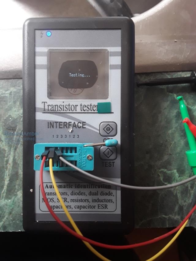
Another thing I'll be needing when mosfets come in I bought this off eBay for under twenty bucks it's very light feels very cheap made but it seems to work well I was pretty impressed that tells you the pinout tells you the voltage capacitance and tells you what kind of component it is
I'm not understanding how the mosfets work I'm getting confused with the source and drain It don't take much by the way
I'm going to look for a class or two on mosfets to take Then I'm going to get started right back on this little board I want to make sure that I get it up and running right and have a good understanding before I go to the big boardEdited by BenandAmber 2019-03-29be warned i am good parrot but Dumber than a box of rocks
BenandAmber Guru Joined: 16/02/2019 Location: United StatesPosts: 961
Posted: 11:19pm 27 Mar 2019
Copy link to clipboard
Print this post
Wise Guys the reasons I post To get help learning Friendship to help others that research this they'll be able to read my post where all you guys have chimed in and gave excellent adviceEdited by BenandAmber 2019-03-30be warned i am good parrot but Dumber than a box of rocks
BenandAmber Guru Joined: 16/02/2019 Location: United StatesPosts: 961
Posted: 02:03am 01 Apr 2019
Copy link to clipboard
Print this post
Success
We changed out irf p 2907z to hy4008
We put 14 gauge wire overall input and output traces soldered it all in where no bare wires showing
We are using the 15v tvs zener diodes that the one and only alsome Poida instructed us to do along with all the other modifications he suggested
poida wasn't the only one that we got good advice from and we appreciate all of you guys and gals that gave us good advice along the way without all you guys this wouldn't have been possible for us
We really like this forum and the good people on it and hope 2 have more successes in the future and maybe one day get good enough to give a little advice ourselves
Peace love and good health to all
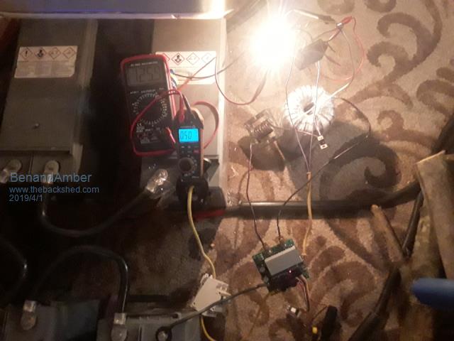
Running a light
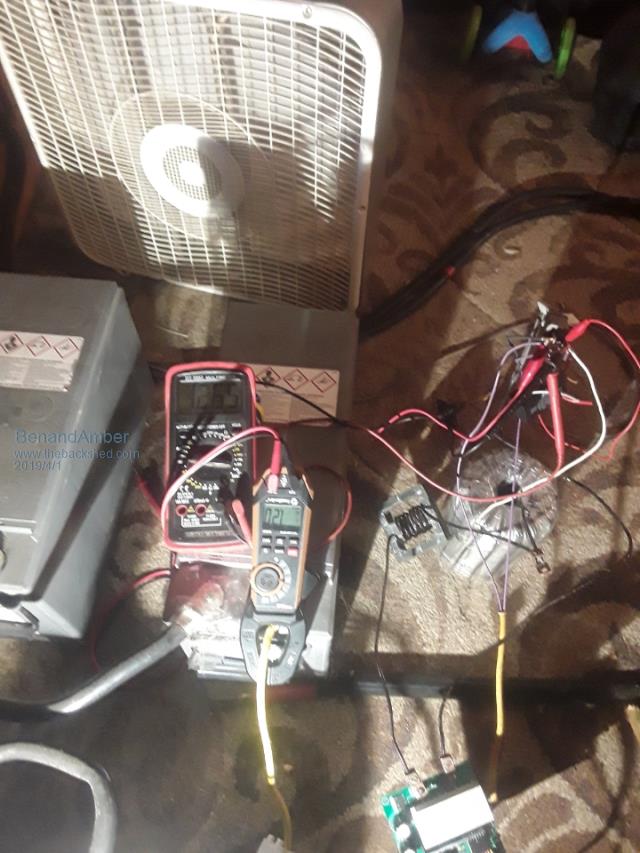
Running a box fan
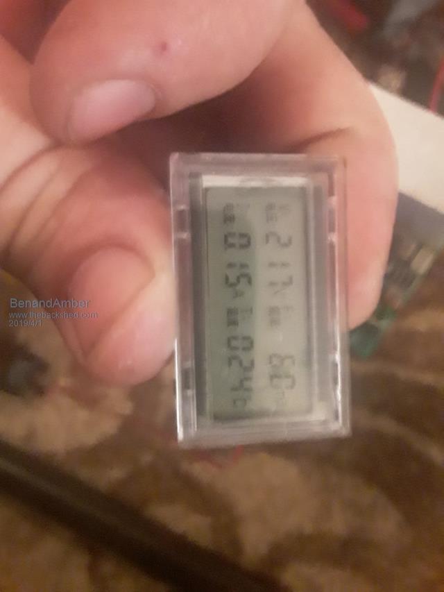
This is the little tiny not worth buying screen that comes with EGS 002 card
none of the information on it is the same as my multimeters the temperature and Hertz is right
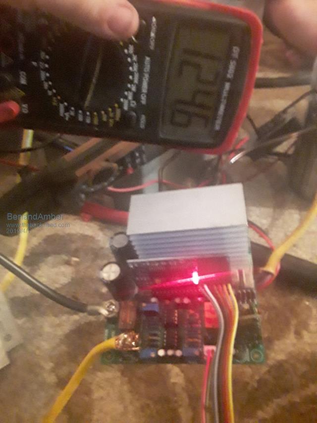
my voltage is a little high I need to set it down a little bit more 126 volts at end of testing
the idle current is below half a amp o.39
the temporary inductor filter makes a funny noise
I didn't run it very hard tonight
I did let it run for a couple hours
During testing the mosfet stayed room temperature without a fan on themEdited by BenandAmber 2019-04-02be warned i am good parrot but Dumber than a box of rocks
poida Guru Joined: 02/02/2017 Location: AustraliaPosts: 1392
Posted: 08:26am 01 Apr 2019
Copy link to clipboard
Print this post
Good to see you get the little inverter going.
Time to put a few loads on it, see how it runs. Reasonable loads, 500W or 150W things like LCD TV, or computers, etc.wronger than a phone book full of wrong phone numbers
BenandAmber Guru Joined: 16/02/2019 Location: United StatesPosts: 961
Posted: 06:27pm 01 Apr 2019
Copy link to clipboard
Print this post
Yes poida that is good advice
Notice I did everything exactly how you told me to
So in other words if you go by what you have posted on this form earlier
and you know the difference between gate and source it will work out very well
I need to test it hard
I've only ran light bulbs and box fans so far for a couple hoursEdited by BenandAmber 2019-04-03be warned i am good parrot but Dumber than a box of rocks
LadyN Guru Joined: 26/01/2019 Location: United StatesPosts: 408
Posted: 06:32pm 01 Apr 2019
Copy link to clipboard
Print this post
Ben,
One good test I think would be halogen lamps or headlights.
They have a good surge characteristic that could give you confidence in hooking this up to a fridge or AC.
A bit harder than the fan but not as bad as a fridge or AC.
BenandAmber Guru Joined: 16/02/2019 Location: United StatesPosts: 961
Posted: 06:40pm 01 Apr 2019
Copy link to clipboard
Print this post
Yeah that sounds good ladyN
But that may be asking a lot out of this little tiny 4inch by 4inch inverter
with only 4 in total mosfets and little tiny capacitors
by the way that's going to change after testing
The thing that I got out of this test that podis design is repeatable by anyone
that knows the difference between gate and Source on a mosfet
which I didn't understand to begin with that's the only reason I blew it up the first time no one's fault but mine
So the conclusion of this test will be anyone reading this post we'll know that they will be able to make their own inverter with one of these cheap Chinese boards
As you know I am not quite there yet but poida the grate has done this and has been running it for quite a while now
I would definitely be amazed if it would run a refrigerator or a air conditioner
Thank you for your time and thanks for postingEdited by BenandAmber 2019-04-03be warned i am good parrot but Dumber than a box of rocks
BenandAmber Guru Joined: 16/02/2019 Location: United StatesPosts: 961
Posted: 08:55pm 01 Apr 2019
Copy link to clipboard
Print this post
If all the experts on here agree
I think someone like you ladyN a really fast typer and a good writer
should one day take all this information and put it in one post without all the extra stuff
readers would have a lot less reading to do if they wanted to build one themselvesbe warned i am good parrot but Dumber than a box of rocks
LadyN Guru Joined: 26/01/2019 Location: United StatesPosts: 408
Posted: 04:52am 02 Apr 2019
Copy link to clipboard
Print this post
My physics teacher who has a PhD does not understand how mosfets work but with his and everyone else's help on this forum, this is what I understood:
1. The gate is the terminal that controls the resistance between the gate and the source 2. The mosfets have inherent capacitances all over but in our case, the most important inherent capacitance is the gate capacitance. We want to charge it ASAP or it will be in the non-saturated mode which is where it starts to get hot. THIS is where most of the damage happens 3. Use an isolated gate driver wherever possible to minimize the issues
Ok, anything for you Ben.
I have not built an inverter yet and you already have one working so that's amazing.
Why don't you create a detailed writeup or/and video of how to make a toroid?
THAT will be very very valuable to a lot who are starting out
Congratulations on the first inverter build. I hope to one day replicate your success!
BenandAmber Guru Joined: 16/02/2019 Location: United StatesPosts: 961
Posted: 12:56pm 02 Apr 2019
Copy link to clipboard
Print this post
Amber built the Transformer ladyN and we did everything except for the low side Winding over a year before we got on this form
and guess what we are going to do a warp speed inverter as soon as we get a chance happy happy joy joy
Warpspeed is pretty awesome guy I think you already know this though kind humble generosity would be just a few of the words to describe the man
We have been testing this little board and it seems Rock Solid so far
We are trying to figure out why it kicks off and starts blinking the little light twice after we run Amber's hair dryer and my heat gun at the same time
Amber's hair dryers pretty big one
The reason I'm confused is because it has no 393 chip on the little board and we did the modifications that poida the great recommended
We didn't know it had any onboard current protection after modifications unless it's shutting off because of battery current
We only have four batteries currently hooked up there are 144 amp hour batteries
We have bigger capacitors to put it on on it also after testing is completeEdited by BenandAmber 2019-04-03be warned i am good parrot but Dumber than a box of rocks
tinyt Guru Joined: 12/11/2017 Location: United StatesPosts: 431
Posted: 02:35pm 02 Apr 2019
Copy link to clipboard
Print this post
The way I understand the 393 chip removal modification is that it still allows the EG8010 chip to monitor IFB. So the chip can still report and react to overcurrent condition.Edited by tinyt 2019-04-04
BenandAmber Guru Joined: 16/02/2019 Location: United StatesPosts: 961
Posted: 04:48pm 02 Apr 2019
Copy link to clipboard
Print this post
Thanks tinyt
I need to get more power I am only getting about 8 amps at 120 volts
Then it kicks off I put bigger mosfets in it it made the tracks a lot bigger should be able to handle more
I just can't figure out how to turn the current up
From no load to right before it kicks off the output voltage drops about four volts
That might have something to do with it Also I just don't knowEdited by BenandAmber 2019-04-04be warned i am good parrot but Dumber than a box of rocks
tinyt Guru Joined: 12/11/2017 Location: United StatesPosts: 431
Posted: 06:39pm 02 Apr 2019
Copy link to clipboard
Print this post
In the EG8010 figure 6-6, there is a 0.01 ohm resistor connected to the mosfet source and IFB of the EGS 002. If your inverter is designed to this schematic and you lower the value, it will change the IFB sense threshold. Warning, it can also create a lot of fireworks.
BenandAmber Guru Joined: 16/02/2019 Location: United StatesPosts: 961
Posted: 09:12pm 02 Apr 2019
Copy link to clipboard
Print this post
Thanks tinyt
I might give that a trybe warned i am good parrot but Dumber than a box of rocks
BenandAmber Guru Joined: 16/02/2019 Location: United StatesPosts: 961
Posted: 09:44pm 02 Apr 2019
Copy link to clipboard
Print this post
Okay I guess it was just a simple as turning a potentiometerbr
Boy poidas design is better than what I thought
I thought with the upgrades that part of the circuit wouldn't work anymore it does
I got it set up to about 16 amps AT 120 volt
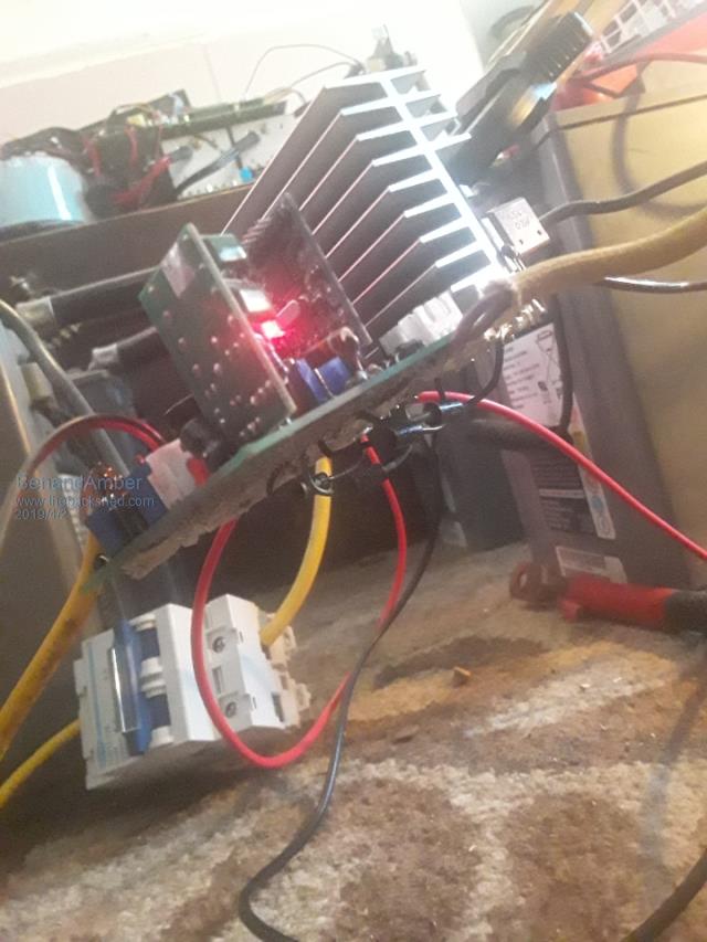
I'm very happy with this IT is literally 4in by 4in inverter board
a fan would probably have to be ran if you was going to pull that much amperage MOrE than a couple of minutes
Now a new question
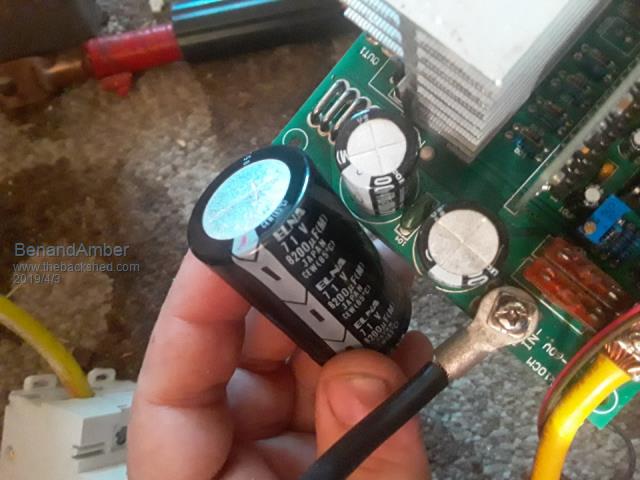
I have a capacitor i only have one of them it is 8200uf
would it be okay to add this without taking the other two little capacitors off
or should I take them off i only have this one bigger one
there is a little tiny ceramic capacitor in between the other two tiny capacitors on the board thay are 470uf
Edited by BenandAmber 2019-04-04be warned i am good parrot but Dumber than a box of rocks
BenandAmber Guru Joined: 16/02/2019 Location: United StatesPosts: 961
Posted: 01:02pm 03 Apr 2019
Copy link to clipboard
Print this post
Staregazer drop by this morning
i had to show him what the little board could do Goofing around and testing
I turned this thing all the way up to 20 amps at 120 volts
running a big hair dryer on high running my heat gun two box fans A big flood light bulb needless to say he was very impressed
I will be doing my 10000 watt board the exact same way
I can not thank poida the great enough Words can't describe how much I appreciate him he didn't only show me how to do it. He gave me the confidence to do it
I don't think it would be good to run this at 20 amps120v all the time but the little board does it and doesn't complain
the mosfet do get pretty warmin just in 3 or 4 minutes of running at this high of amps
with just a hair dryer around a thousand Watts they barely get warm
The only thing left to do now is mount in the Box it goes in when I get all that done I'll post pictures
So the conclusion of this is anybody out there that needs a cheap hard-working inverter
just follow poida the great's instructions that are in the beginning of this post
And hope that all of the good people on here well give you good advice like they gave me
Thank you to all you guys are girls me and my family really appreciate all of your help along the way Edited by BenandAmber 2019-04-05be warned i am good parrot but Dumber than a box of rocks


 and guess what we are going to do a warp speed inverter as soon as we get a chance