
|
|
Forum Index : Electronics : Micro controller driven Warpverter
| Author | Message | ||||
| Warpspeed Guru Joined: 09/08/2007 Location: AustraliaPosts: 4406 |
Yup. And they are a direct plug in replacement for the HCLP3120. Cheers, ĀTony. |
||||
| Solar Mike Guru Joined: 08/02/2015 Location: New ZealandPosts: 1124 |
Come on bite the inevitable bullet, I have been using smd's for the past few years, they are not really any problem for DIY with a bit of practice, use a hot air station to solder them and a good quality solder paste (dont get the cheap paste or solder from AliExpress, its rubbish) Cheers Mike |
||||
| Warpspeed Guru Joined: 09/08/2007 Location: AustraliaPosts: 4406 |
I did a lot of surface mount work before I retired, its not too bad if you have an expensive stereo microscope, all the hot air soldering equipment, and all the components on hand. But for home use its an entirely different matter. How do you breadboard something with surface mount parts ? Oh you don't. You carry two stocks of every component in both through hole (for prototyping) and surface mount for final assembly. The components can be difficult to recognise, they are just too small for full identification, especially the small capacitors. Semiconductors can be difficult too. No thanks. I really do not care if my circuit board ends up three times the size, many parts cannot be reduced in size anyway. It just does not make sense to have 10 watt wire wound resistors and TO247 sized mosfets screwed to a huge heatsink, then use surface mount parts "to make it small". Cheers, ĀTony. |
||||
| wiseguy Guru Joined: 21/06/2018 Location: AustraliaPosts: 998 |
I bit the bullet a long while ago, below is a picture of one of my last power design before I semi-retired. 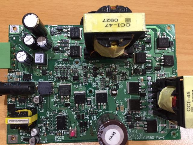 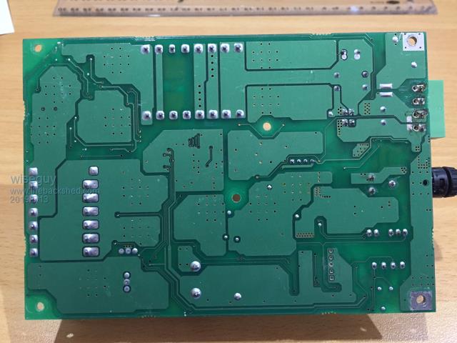 It was a rail 200W power supply input range 53 - 140VDC with no heat sinking required at all, efficiency worst case ~ 93% at full load. Galvanically isolated, uC supervised, output current overload shutdown auto restart. Can I have my training wheels removed now  My latest stuff uses 0603 & 0402s - and I really hate it when I have to build the prototypes! I was considering other home constructors as well as myself in my design approach, I do have hot air gear at home - but I might try Marks frying pan trick..... PS last week I picked up an "empty" plastic bag to put some parts in - a closer inspection revealed ~ 50 x 0402 resistors held by static electricity at random places across the internals - they were near as dammit invisible to my old eyes. If at first you dont succeed, I suggest you avoid sky diving.... Cheers Mike |
||||
| Solar Mike Guru Joined: 08/02/2015 Location: New ZealandPosts: 1124 |
I think so, have to agree with you all on the size of the smaller devices, they can be a pain, I dont use any smaller that 0805, too easy to loose. I remember assembling a pcb last year, went to pick up a 0805 cap with tweezers and ping it vanished somewhere, then next day we went on holiday up north for 1 week, found it 3 days later on the table of motel unit, must have been clinging to bit of clothing.... |
||||
| wiseguy Guru Joined: 21/06/2018 Location: AustraliaPosts: 998 |
Mike where do you get your "good quality" solder paste in hobbyist quantity at reasonable pricing ? I was not involved in any selection or purchase decisions of the solder pastes we used during manufacture. If at first you dont succeed, I suggest you avoid sky diving.... Cheers Mike |
||||
| Warpspeed Guru Joined: 09/08/2007 Location: AustraliaPosts: 4406 |
At least with through hole construction, you have the choice of using sockets for your integrated circuits. That can save a lot of time if there is ever a problem. Cheers, ĀTony. |
||||
renewableMark Guru Joined: 09/12/2017 Location: AustraliaPosts: 1678 |
When building the Poida nano board I found the smd drivers were heaps cheaper and easier to get, so made up some little plug in boards. That's always an option where costs drive you away from plug in chips. Still quick to swap out.  Cheers Caveman Mark Off grid eastern Melb |
||||
| gaspo Regular Member Joined: 25/06/2018 Location: AustraliaPosts: 61 |
I buy this one - excellent for working with smd parts. Paste is very thick, I put a little under the chip to hold it in the place while I solder the corner pins. I use it for soldering through hole parts too, it doesn't leave dirt after soldering. |
||||
LadyN Guru Joined: 26/01/2019 Location: United StatesPosts: 408 |
I see there's a lot of insight into this hot air rework station: I would love to hear your feedback here https://www.thebackshed.com/forum/forum_posts.asp?TID=11388&PN=1&TPN=1 |
||||
| Solar Mike Guru Joined: 08/02/2015 Location: New ZealandPosts: 1124 |
I use this MG Chemicals No Clean Solder Paste not cheap, but one tube will last for 12 months, then throw away left over... it doesnt keep. For solder I use the stuff with 2% silver, same outfit sells it, flows really well and wont crystallize with heat. Don't use any lead free, cannot see the point. Have tried with solder and solder pastes from china and its generally crap, or counterfeit of a quality product, their solder wire is horrible, made from old car batteries or something. Cheers Mike |
||||
| wiseguy Guru Joined: 21/06/2018 Location: AustraliaPosts: 998 |
Totally agree I also wouldn't use anything other than machined pin type - if they aren't available then I'd rather solder the suckers in direct ! Thanks for the reply Gaspo - I thought you'd dropped off the planet - good to see you are still lurking around. Does that paste have a use by date too - can it be extended by keeping it in a fridge ?? Totally agree - if lead free is the answer - it must have been a dumb question ! I suffer it when needed but avoid it for serious & reliable stuff. I've never tried solder with added silver will try some out. Great comment about the battery/solder ! If at first you dont succeed, I suggest you avoid sky diving.... Cheers Mike |
||||
| gaspo Regular Member Joined: 25/06/2018 Location: AustraliaPosts: 61 |
There's no expiry date on the box. I store it on the shelf in the garage - no special treatment. |
||||
| Warpspeed Guru Joined: 09/08/2007 Location: AustraliaPosts: 4406 |
For a very short time I worked for a company that imported some truly awful lead fee solder from China by the pallet load. We sold it to our victims... er, I mean customers, but WE were never allowed to use it ourselves in our in house service department. So much for crafty business ethics. Cheers, ĀTony. |
||||
| nickskethisniks Guru Joined: 17/10/2017 Location: BelgiumPosts: 415 |
Another idea for those that can't use the big elco's and maybe want to use a lot of cheaper smaller elco's. It's easy to use small pcb's like 10cm*10cm that are verry cheap at the moment. Or use the pcb's with a copper layer and carve the tracks, there are just 2.  You can cascade this verry easily to have a big bufferbank. 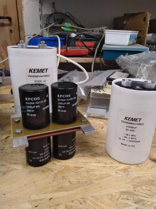 The aluminium bar could be a 90░ angle profile, so you can make a lot of easy connections. It's more difficult with a flat bar to make tap the current. You need a good thickness to avoid the elco pins touching. 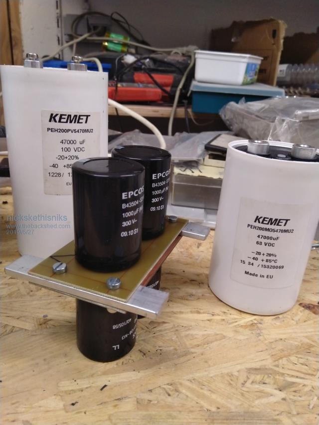 |
||||
| Tinker Guru Joined: 07/11/2007 Location: AustraliaPosts: 1904 |
Clever idea but it would require a lot more room for the 47 capacitors to make up the same capacity as the one single Kemet cap shown in the picture Perhaps OK for a test rig that requires a big capacitor and heaps of smaller ones clutter up the junk box, waiting to be used  . .But for a warpinverter even more space for the 100,000+ uF capacitor is required. All considered, the $AU38.50 I paid for each of my 33,000uf/100V caps is not too bad. These are big (75mm x 200mm) but a lot easier to fit into the inverter enclosure. A warpinverter with its 4 transformers, up to a dozen PCB's, 32 HY4008's (for mine) and lots of other parts could hardly be considered a budget project. Especially if one was to do a 'proper job' to make something that works reliably for many years. Klaus |
||||
| BenandAmber Guru Joined: 16/02/2019 Location: United StatesPosts: 961 |
Has anyone tried that frying pan and sand way of soldering on components that renewableMarkput put link 2 on page 15 Boy it looks really easy and really fast be warned i am good parrot but Dumber than a box of rocks |
||||
| renewableMark Guru Joined: 09/12/2017 Location: AustraliaPosts: 1678 |
The guy on the video has! The frying pan full of sand is just a way to apply even heat, looks like a pretty rough method though. You are probably better off with a hot air station for better control I think. Cheers Caveman Mark Off grid eastern Melb |
||||
| Solar Mike Guru Joined: 08/02/2015 Location: New ZealandPosts: 1124 |
I would like to see how you would solder up double side pcbs with components on both sides with that "Sand" method.... most smd components have a spec for soldering and the time for 300 degree and above temperatures is normally limited to 10 seconds or so, that sand method is going to be too slow in heating and cooling and most likely be detrimental to the components life. Hot air station would be a better choice as per Marks comment. Cheers Mike |
||||
| Warpspeed Guru Joined: 09/08/2007 Location: AustraliaPosts: 4406 |
I agree with Klaus. At least start out with a couple of decent quality low ESR capacitors and see how that goes. Its not going to blow up on the launch pad if the electrolytics wimp out! Same with the mosfets. You can start with four very basic low power bridges to get it working initially. Then build a bigger one for the large #1 inverter. That can eventually become #2 when you build a real monster inverter for the final #1. It can be built in stages and upgraded. Only the four transformers need to be full size right from the start. If the dc supply ends up all noisy and horrible, its a problem that can be fixed with a capacitor upgrade. Get it up and running first, and see if the sine wave and dc supply both remain clean. The stiffer you can make the dc supply, the more immune to waveform distortion the Warpverter is going to be with really nasty loads. Cheers, ĀTony. |
||||
