
|
|
Forum Index : Electronics : Micro controller driven Warpverter
| Author | Message | ||||
renewableMark Guru Joined: 09/12/2017 Location: AustraliaPosts: 1678 |
I went over to Poida's place today and he tested the little boards. They start up around 35v with no load on them. When you place a load on them they need much more to start up. With 15mA load they start at 48V. With 30mA they start at 50V. So Tony when these get powered up is there any load on them? Also these were claimed to be 450mA, but they only run stable at 200mA, is that enough? Cheers Caveman Mark Off grid eastern Melb |
||||
| Warpspeed Guru Joined: 09/08/2007 Location: AustraliaPosts: 4406 |
Just had a look at the specs for the HCPL3120 gate driver chip. https://cdn.datasheetspdf.com/pdf-down/H/C/P/HCPL-3120-Agilent.pdf Page 9, Max supply current 16mA. Page 10, UVLO (undervoltage lock out) worst case supply voltage to start up 13.5v. Typically 12.3v. That is why we need a +15v supply. The little +5v power supply on the control board does have some load on it, about 25mA for the ICs and about 80mA for the sixteen opto isolators it has to drive. Only half of them can be on at any one time, with about 10mA through each one. That is roughly 105mA of load from a 700mA rated supply. That might be worth checking out as well. If this is going to be a problem, we may need to look at all this a bit more. Klaus has come up with the solution of powering all these little supplies from a boosted to +60v dc source. About five watts will be required to drive all of those small boards, seventeen of the little devils in all. Cheers, �Tony. |
||||
| wiseguy Guru Joined: 21/06/2018 Location: AustraliaPosts: 1016 |
Haven't been following this thread closely but maybe a couple of suggestions that might help. Some have mentioned using Mosfets so perhaps 15V drive is not essential ? Why not use an optical driver that will happily operate on 12V such as TLP250, FOD3182 or if you dont mind surface mount TLP705. These are all happy to work from 10 - 30V and draw 3 to 4mA when idling. Then the 12V power supplies can be used without modification too. The vertical Power modules I brought start at 29V, running at 30V I could easily pull 100mA from the 15V supply and its output stayed rock solid. Note they did start up ok with that load connected. I brought them Here If at first you dont succeed, I suggest you avoid sky diving.... Cheers Mike |
||||
| Warpspeed Guru Joined: 09/08/2007 Location: AustraliaPosts: 4406 |
Those vertical supplies look like the best solution Mike. When I designed my own inverter it was for +90 volts dc minimum, and I used the HCLP3120 because I have been using them for a very long time, and have a lot of them here. So all these problems never arose in my case. Anyhow, had a quick look at a Toshiba TLP250 https://toshiba.semicon-storage.com/info/docget.jsp?did=16823...TLP250(INV) They say 11mA and input voltage limit of 10v to 30v (but recommend 15v to 30v) Nothing in there about having an under voltage lockout, so it may not have that feature. The Fairchild FOD3182 is 10mA to 16mA and 10v to 30v input range with under voltage lockout worst case start up of 9v. https://www.onsemi.com/pub/Collateral/FOD3182-D.pdf Cheers, �Tony. |
||||
| wiseguy Guru Joined: 21/06/2018 Location: AustraliaPosts: 1016 |
I don't know what data sheet I was looking at for the TLP250 but it obviously wasn't the right one ! I agree about the 11mA and also it is flagged not for new design and 15 - 30V range so I would not have recommended it either. I read the FOD3182 data sheet on page 5 as 10 - 16ma for forward LED current. I read IDDH & IDDL as typically 2.5mA, worst case 4mA, with no load connected. Maybe I shouldn't read data sheets when Im so tired and I got it wrong? The FOD 3182 is my choice for my inverter design as I prefer 12V Gate drive if possible. There is nothing else I could find in DIP package with reasonable specs & that works fine at 12V I have almost finished my 16 FET power PCB, for all the auxiliary gate & bias supplies (4) there is a sub board that either solders or plugs in to the power PCB on a 10 way sip. There are two options, either wind a little transformer and put a few other bits on circuit board A, or use another little circuit board B that you can solder 4 of those little vertical converters into instead. A runs off 12V (an auxiliary from 48V) B runs off 48V direct. I dont want to buy batteries yet & I haven't received the free lot that someone offered and is still coming, how successful is using 4 decent automotive/truck style batteries for some 2 - 4kW testing ? (obviously not for long periods.....) If at first you dont succeed, I suggest you avoid sky diving.... Cheers Mike |
||||
| Warpspeed Guru Joined: 09/08/2007 Location: AustraliaPosts: 4406 |
Have to agree, the FOD 3182 is a direct plug in swap for the HCPL1320 and is a much better choice. Some of the more recent chips are quite nice, but most are now only available as surface mount, which causes a whole lot of problems at my age. Unless its a DIP package and plugs into a socket, its very unlikely to get used around here. When I made my inverter, the 15v power supplies were readily available. Now they have all vanished. I just cannot imagine why that has happened. Cheers, �Tony. |
||||
| poida Guru Joined: 02/02/2017 Location: AustraliaPosts: 1392 |
I want to show you all this isolated supply: $2.20 US each, 5,9,12,15V versions etc. What is special is it starts on 24V. 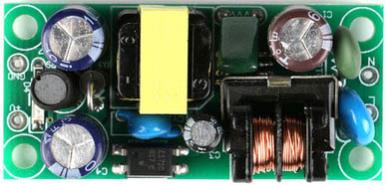 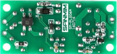 An NTC and a MOV on the input, and a common mode choke. This is a nice supply It took over a month to get to me. wronger than a phone book full of wrong phone numbers |
||||
| Tinker Guru Joined: 07/11/2007 Location: AustraliaPosts: 1904 |
Did you try the startup under load? Fit a resistor suitable for the output voltage (39 Ohm for a 15V module) to the output terminals and check if it still starts up at 24V. If so you got a winner. Klaus |
||||
LadyN Guru Joined: 26/01/2019 Location: United StatesPosts: 408 |
Peter, the shipping shows $2+ - as much as the $2 module itself. It could make sense to build a flyback convertor based off these parts (or others more suitable) that meet our requirements? I have been planning to learn about flyback convertors myself but am currently far from understanding the whole thing myself but am getting to it. Slowly. |
||||
| nickskethisniks Guru Joined: 17/10/2017 Location: BelgiumPosts: 428 |
I think wiseguy posted a schematic somewhere in an other thread. For us mosfet users it's maybe an idea to make a small pcb to connect mosfets to a busbar or cable with lugs, I made some "prototype" 3pcs mosfet "brick". I think the idea is expandable to more mosfets and half bridge design. Because we are switching at 50 hz it would be no problem? We could easily add snubber and or add on mosfetdriverpcb if necessary. Some thoughts? 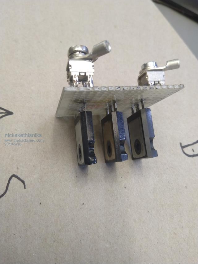 We could then sandwich the mosfets between (in this case 8mm) aluminium bars. This bars could be connected to a heatsink with isolating pad. Or first to a smaller rectangular alu plate and then isolating pad, then main heatsink. On the picture the aluminium bars are to long. 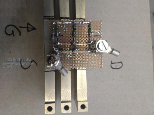 I can do more finetuning for better view, but I hope you get my idea. |
||||
| renewableMark Guru Joined: 09/12/2017 Location: AustraliaPosts: 1678 |
This is interesting Cheers Caveman Mark Off grid eastern Melb |
||||
| johnmc Senior Member Joined: 21/01/2011 Location: AustraliaPosts: 282 |
As you say Mark, very interesting The sand looks like aluminium oxide abrasive, that I use for sand blasting. cheers john johnmc |
||||
| johnmc Senior Member Joined: 21/01/2011 Location: AustraliaPosts: 282 |
Mark, I had a memory lapse the abrasive is garnet I think not aluminium oxide  cheers john johnmc |
||||
| Tinker Guru Joined: 07/11/2007 Location: AustraliaPosts: 1904 |
Agree, its an interesting method. I think its just ordinary beach sand, used to moderate the heat on the pan bottom. However, the whole board needs to be populated with SMD parts. Does anybody know what kind of glue is used to hold the part in the other method shown? It would help my so far single SMD IC soldering if it was held securely while my no longer steady hands manouvre the fine soldering iron tip in place. I do use a small spring clamp but that can angle the pins off the board on one side of the IC. Klaus |
||||
| wiseguy Guru Joined: 21/06/2018 Location: AustraliaPosts: 1016 |
The "glue" is usually the solder paste. It has a consistency not unlike toothpaste albeit a bit thicker. After the stencil is used to paste the pcbs the parts are pushed onto the pasted pads and "stick" to them. Of course a fumble or "oops" moment can be disastrous after fitting all the parts. I forgot to mention glue can be used for smd parts but that is usually for wave soldered SMD parts in my experience. That is why I am designing my inverter with through hole parts - although the time is coming where we wont have a choice but to use SMD but we arent there yet! A lot of good state of the art semiconductor ICs and ancillary stuff is only made available in SMD, so sometimes your hand is forced.. If at first you dont succeed, I suggest you avoid sky diving.... Cheers Mike |
||||
| Warpspeed Guru Joined: 09/08/2007 Location: AustraliaPosts: 4406 |
Now this is a truly brilliant idea. My current Warpverter has never had a single blow up, but if it ever does go bang, I could slide a replacement IGBT power block under the aluminium busbars and replace its small driver board in probably about five minutes. None of the destruction can propagate back into the rest of the inverter. Any destruction will be highly localised and quickly and easily replaced without any soldering required. Mosfet high power modules are available, but are just totally impractical for cost reasons. But this idea of home brewing our own low cost replaceable mosfet power module made from multiple HY4008s, with a built in optically isolated gate driver is a very promising concept. It raises the screw terminal block idea up to the next level. Circuit boards are now so cheap to get made, a badly burned and smoke damaged home brew module could be a throw away item just not worth repairing. Cheers, �Tony. |
||||
| poida Guru Joined: 02/02/2017 Location: AustraliaPosts: 1392 |
This is a 12V module. I placed a 5W 47R across the output. It starts with 24V DC, but it can not produce 12V on output, only 8.3V with the 47R load. 1.5W maybe. 12V output arrives once input is about 36V. In a few minutes, the combined SMPS IC/MOS switch warms up enough to reduce power a little, and so it needs about 39V to make the 12V output. I will get a few of these for my isolated PS needs. I like the 24V startup. I thought some here might like the look of them, they seem better quality than the ones Mark has bought (which will do the job fine anyway). wronger than a phone book full of wrong phone numbers |
||||
| Warpspeed Guru Joined: 09/08/2007 Location: AustraliaPosts: 4406 |
If this is for a Warpverter isolated gate drive power supply, the gate driver chip only needs about 15mA to run. So a 1K load might be a more realistic test than 47 ohms (15v at 15mA). Cheers, �Tony. |
||||
| Tinker Guru Joined: 07/11/2007 Location: AustraliaPosts: 1904 |
Yes, they look good but they are too big for the narrow driver boards I have designed. I have some 15V modules on order, we shall see how they start up. In the worst case I will use a voltage booster to 60V to power the modules, the driver PCB's have links to allow for that. There is also a box full of modules I'd ordered here, one lot 24V, these were too hard to modify, the others 12V but impossible to modify  . . These modules turned quite into a saga... Klaus |
||||
| renewableMark Guru Joined: 09/12/2017 Location: AustraliaPosts: 1678 |
So the FOD3182 is ok on a 12v supply yeah? Cheers Caveman Mark Off grid eastern Melb |
||||
