
|
|
Forum Index : Electronics : Micro controller driven Warpverter
| Author | Message | ||||
mackoffgrid Guru Joined: 13/03/2017 Location: AustraliaPosts: 460 |
Poida, I used the blue pill , and using Roger Clarkes Core. Give me a few hours, as I've debugged most of it. The STM32F103 is certainly a more capable processor. I would say it would be a better candidate for this project - The only proviso is the question of noise immunity - I have used Nano's in what could be called semi-noisy environments without trouble. I have no experience using these 32 bit, 3v3 Arm processors in more harsh environments. My Code, which is almost debugged now (The first one is riddled with dumb bugs  ) has these features: ) has these features:It runs at 1024 steps per cycle, the same as Tony's clock board. So that runs at a frequency of 51209.1... Hz, or a cycle time of 19.52... microseconds, and results with an output frequency of 50.0088... Hz Adjusting the output voltage is simple, but I haven't fully implemented the ADC. At the moment I'm using callback interrupts to collect ADC data, which is efficient enough, but there are other modes to explore - Continuous mode is probably the most appropriate. I build the tables during the setup routine, probably should be hard coded into program memory eventually. I'll post an update this evening complete with any libraries. Cheers Andrew |
||||
| mackoffgrid Guru Joined: 13/03/2017 Location: AustraliaPosts: 460 |
Done for the night Libraries: Streaming, PString are just libraries I like for formatting messages. 2019-03-29_213553_stm32_StepInverter_0329_2133.zip 2019-03-29_213710_Libraries_for_StepInverter.zip 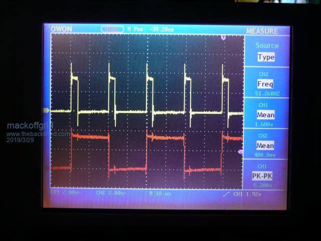 PC14 (red) toggles in the timer interrupt and PA4 (Yellow) is set High on the start of the timer interrupt and cleared at the end of the proc_nextOutputValue() which finds the next voltage level and load the value for the outputDriver. As you can see it does it comfortably. Todo: more tidy up and commenting, ADC, ON-Off control. Cheers Andrew |
||||
| mackoffgrid Guru Joined: 13/03/2017 Location: AustraliaPosts: 460 |
Latest version of stm32_StepInverter 2019-03-30_230352_stm32_StepInverter_0330_2059.zip A bunch more tidied up, lots of commenting (a bit more to go) ADC running in DUAL simultaneous, continuous converting mode. Reading Battery voltage and current. Current is not used. Continuous converting means I just have to read the data registers at a frequency slower than the conversion rate (better than 6kHz atm). This I believe is the quickest way for the processor. Im only taking 16 samples per 50Hz cycle and running it through an exponential MA. I'll push any further changes to stm32_StepInverter GitHub Cheers Andrew |
||||
| Warpspeed Guru Joined: 09/08/2007 Location: AustraliaPosts: 4406 |
Looking really good Andrew. The actual software is way beyond my comprehension, but if it creates all the necessary waveforms, that is all it has to do. When you make up a final PCB for it, if you could use the same kind of plugs and pin outs as my board, it would make both our efforts plug and play compatible. Cheers, ĀTony. |
||||
| mackoffgrid Guru Joined: 13/03/2017 Location: AustraliaPosts: 460 |
Thanks Tony, No worries re the plugs and compatibility. I'm going to go on to use my scope board to read in the 8 outputs from any clock board and synthesise the AC waveform. It could show if there is any DC bias, frequency etc and a good GO-NOGO test. cheers Andrew |
||||
| Warpspeed Guru Joined: 09/08/2007 Location: AustraliaPosts: 4406 |
I did exactly the same thing. Fed all my mosfet gate drive signals into a lookup table (only 81 addresses) and the output of that fed into an analog to digital converter. Each step being three bits in the A/D gives a nice high 243 bits peak to peak output signal. Its great ! I can look at everything and see everything. I used the drive to the eight upper mosfets to address the lookup table. Negative most step data 1010 1010 AA hex Zero crossing data 000 000 00 hex Positive peak data 0101 0101 55 hex Cheers, ĀTony. |
||||
| poida Guru Joined: 02/02/2017 Location: AustraliaPosts: 1389 |
Mack: I've added the mains sync code to the STM32 blue pill code (I just got today's version from github) It works a treat. I chose at random and likely a poor choice, pin PA1 as the sync source. This is a 3.3V pin, I feed it a square wave with high of about 3.3V, a low of about 0.5V and it works fine, tracking changes from 49 to 51 Hz with ease. I put PB7 output into DSO channel 1 and trigger off that. Put the test square wave into ch2 and ch1 alters it's phase and freq to lock onto ch2. Have a play if you like. 2019-04-02_113936_stm32_with_mains_sync.zip wronger than a phone book full of wrong phone numbers |
||||
| mackoffgrid Guru Joined: 13/03/2017 Location: AustraliaPosts: 460 |
Poida Great job.  Your code just slotted in. I admit I haven't looked at your mains sync code but imagined it would be something like that. I haven't played with it yet but I definitely will. I'm a bit in the middle of doing a Step Inverter Snooper (Simulator) - done one on the STM but I'm switching over to the DUE. Your code just slotted in. I admit I haven't looked at your mains sync code but imagined it would be something like that. I haven't played with it yet but I definitely will. I'm a bit in the middle of doing a Step Inverter Snooper (Simulator) - done one on the STM but I'm switching over to the DUE.Pin choices are fine btw Cheers Andrew |
||||
LadyN Guru Joined: 26/01/2019 Location: United StatesPosts: 408 |
Andrew, it's good that you mentioned this as I was building the fakeverter as well. I also had a feature planned for the fakeverter - if it ever sees a signal at its pins that's not in the look up table, it raises an exception. This means the warpverter brain caused an invalid output state/glitch. The problem is correlating the exception caught by the fakeverter and HOW the warpverter brain caused an invalid output state/glitch - i.e. reproducing the error state. The original warpverter brain has a nice output latch that helps synchronize the output bits. I wonder if it could be possible to pull that off without an external latch. One option could be to use a uC that has enough dedicated ports and write the bitmask directly to the port. I really value the work being done here. Thank you |
||||
| Warpspeed Guru Joined: 09/08/2007 Location: AustraliaPosts: 4406 |
I would not worry too much about the usually illegal 11 hex logic state being fed into any of the inverter stages. The inverter will look after itself by turning on both upper mosfets, and turning off both lower mosfets. That will create a zero output volt condition across the primary winding, and clamp the primary winding just the same as the normal 00 hex off state clamps the two lower mosfets. The 11 state behaves exactly like the 00 state as far as inverter operation is concerned, and its perfectly safe. So don't worry guys, these power stages are fully self protected against both cross conduction and the normally illegal 11 logic state. The power stages are going to be very hard to kill from noise or chaotic data. Its all been thought out very carefully. Designing bullet proof hardware is my job. Its now up to the software guys to give it some smarts. There are two ways to produce suitable time coincident drive outputs. Use one eight bit output port, and eight hardware inverters as I have done. It may be preferable if there are two eight bit output ports available to just use those. Use one eight bit port to drive two inverters with time coincident outputs. And the second port to drive the two other inverters. The U and L inputs to each half bridge must be time coincident or its going to skew the dead time. It would also be preferable if both half bridges switch together. All that requires four time coincident bits, or one half a port to drive one inverter. One last thought. Whatever drives the opto isolators needs to source and sink about 10mA and go essentially rail to rail. Ordinary garden variety 74HC chips just manage to do that. Some low power microcontrollers may struggle, especially when sourcing current. It may pay to read the book of words regarding specific I/O ports and what they can actually do. Cheers, ĀTony. |
||||
renewableMark Guru Joined: 09/12/2017 Location: AustraliaPosts: 1678 |
OK got some wire on the way for the primary of No1 toroid. No 2 toroid will be a 2kw aerosharp. 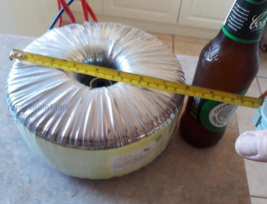 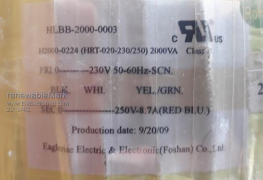 Those windings are going to be useless, so a strip and rewind is in order. I have fixed No 1 toroid to have 128 turns, waiting on cable for the 25 primaries. What numbers would be best for the No2 2kw Tony? Poida, let me know which toroids you want for your machine, there is enough for you to do a double stacked 2kw (4kw) for No1 and then use 1500w for the other three. Or make a smaller machine and have just a 2kw for no1, which will be a lot less winding. Double stacked you'll need to completely strip and rewind, but it's not that bad. It only sends you a little bit crazy, if you are already cracked in the head it's no big deal. We might need someone to put their hand up for circuit board design, I think Tinyt is a tad busy at the moment. Cheers Caveman Mark Off grid eastern Melb |
||||
| Warpspeed Guru Joined: 09/08/2007 Location: AustraliaPosts: 4406 |
O/k Mark for the number two 2Kva transformer. First I need some information. I need to know the magnetic cross section of the core, and you won't be able to measure that until the core is stripped completely naked. Also need to know the diameter of the hole. And what copper wire diameters you have available on hand there to rewind it with. And lastly, I think your big toroid had a combined secondary wire size of around 7.5mm squared (for thirty amps). We need this secondary to have about a similar combined wire size to end up with a similar current rating. If you can come up with all of that, I will have a go at a possible design and explain step by step. Cheers, ĀTony. |
||||
| mackoffgrid Guru Joined: 13/03/2017 Location: AustraliaPosts: 460 |
Tony, The STM32F103.. "BluePill" processors are only 3.3v. I feel the outputs need to be buffered, so HC14s are cheap Cheers Andrew |
||||
| Warpspeed Guru Joined: 09/08/2007 Location: AustraliaPosts: 4406 |
You will need an ACT device that has TTL logic level inputs of 0.8v and 2v. Check out a 74ACT04P4 device available in a DIP14 package Also has absolutely massive output drive capacity :o) http://ecee.colorado.edu/~mathys/ecen1400/pdf/references/74AC04.pdf Cheers, ĀTony. |
||||
| nickskethisniks Guru Joined: 17/10/2017 Location: BelgiumPosts: 416 |
Wow, I'm gonna folow this topic! Maybe I can do the board/circuit design, but @this moment I first need to protect and monitor my "solar energy system". I will come back to that. |
||||
| renewableMark Guru Joined: 09/12/2017 Location: AustraliaPosts: 1678 |
That was fun, do you need it stripped completely to metal, or is this ok? Height 67mm 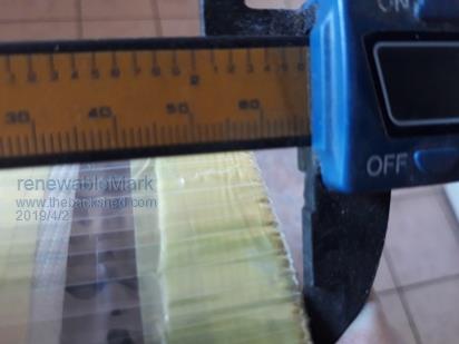 ID 87mm  ID to OD 50mm 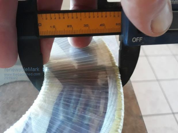 Cheers Caveman Mark Off grid eastern Melb |
||||
| renewableMark Guru Joined: 09/12/2017 Location: AustraliaPosts: 1678 |
Forgot to say the wire I am using is the 1.6mm 2mm2. That is what I used on the bigger 6kw toroid too. 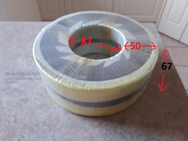 Cheers Caveman Mark Off grid eastern Melb |
||||
| Warpspeed Guru Joined: 09/08/2007 Location: AustraliaPosts: 4406 |
O/K we are off to the races......... The first step is to work out the minimum possible number of secondary turns that will give us a flux density of 1 Tesla with a core cross section of 67mm x 50mm to support 75.0 volts at 50Hz. This is not strictly correct for higher frequency square waves, but all the errors will be on the generous safe side. And I want to keep all this as simple as possible. So we go to our trusty transformer flux calculator and we plug in some trial and error numbers. 75 volts .00005 Mhz (four zeroes) 50Hz 100 turns 33.5 cm squared (67mm x 50mm) Hit "calculate" And we get an answer of 10,084.71 Gauss (10,000 Gauss = 1.0 Teslas in metric measurement) https://daycounter.com/Calculators/Max-Flux-Density-Calculator.phtml So we require a minimum secondary turns of 100. Our transformer ratio will be our (Mark's) minimum dc input voltage of 44.0v up to 75.0v on the secondary. If we have 100 secondary turns and we multiply that by 44/75 we would require 58.6666 primary turns. So we go up to 59 primary turns and try that 59 x 75/44 = 100.56 turns 60 primary turns x 75/44 = 102.27 turns 61 primary turns x 75/44 = 103.97 turns. lets make it 61 turns primary and 104 turns secondary. The circumference of our hole will be 87mm x 3.142 = 273mm circumference. If you want to do it with 1.6mm wire, that has a cross sectional area of 3.142 x 0.8 x 0.8 = 2mm squared, good for only about 8 amps. You would need four layers of that for 30 amps. Now we could with luck fit roughly about 170 turns of 1.6mm wire onto the first layer. A second layer would be six turns less in theory, or 164 turns Third layer six turns less than that 158 turns. Fourth layer six less still 152 turns. So there is going to be heaps of room to fit on 104 turns and four layers of 1.6 wire. Its best if you can spread the turns around evenly on each layer if possible to use the whole width of the available core. Actually three layers of thicker wire might be better if you had the wire to do it, but four layers of 1.6 will definitely do the job. Secondary will be four layers of 2.0mm squared wire 104 turns. Primary will be 61 turns of 8 x 10⁴/61 x 8 = 13.6mm squared wire (or whatever comes close). Cheers, ĀTony. |
||||
| mackoffgrid Guru Joined: 13/03/2017 Location: AustraliaPosts: 460 |
Tony I had some thoughts on approximating the core size of an existing wound transformer like mark has. - Measure the wire size, of each winding. - Add a temporary winding (say 10 or 20 turns) and determine the turns of all windings. - Weigh the transformer. - From here use a spreadsheet for Calcs. - Estimate the copper lengths and weight deriving from above details. This will give us the steel content. - Using the dimensions like Mark has taken, we know the weight of silicon steel, we can play with the spreadsheet until we have a descent approximation for the core size. I realize this is a bit like bush mechanics but ... This is kind-of what I've done Cheers Andrew |
||||
| Warpspeed Guru Joined: 09/08/2007 Location: AustraliaPosts: 4406 |
Commercial transformers operate at a much higher flux density than is desirable for an inverter, so we really need a slightly larger sized core for any given power. But we gain some, because manual winding allows far more of the hole to be used up than would be the case with a commercial toroid winding machine. If we start out with a commercial toroid rated at 2Kw (or whatever) we can pretty much get all of that, but do it at a far lower flux density and idling current. No need for bush mechanics when it can all be worked out properly. Cheers, ĀTony. |
||||
