
|
|
Forum Index : Electronics : 10000 WATT China inverter board
| Page 1 of 5 |
|||||
| Author | Message | ||||
| BenandAmber Guru Joined: 16/02/2019 Location: United StatesPosts: 961 |
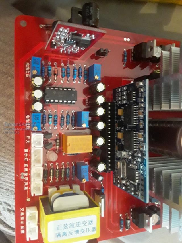    This thing is big and heavy it was under $180 shipped 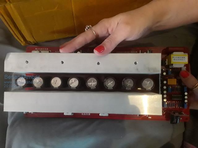 Not what I was expecting it's very heavy and seems to be very well made but the experts on hear will most likely chimed in chime in and let us all know the quality of build 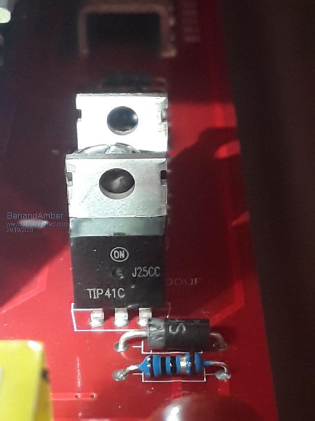 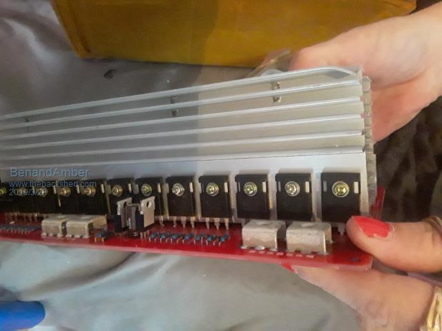 It came very well Packed The outside of box was destroyed buy shipping and the only damage was that one little Bend 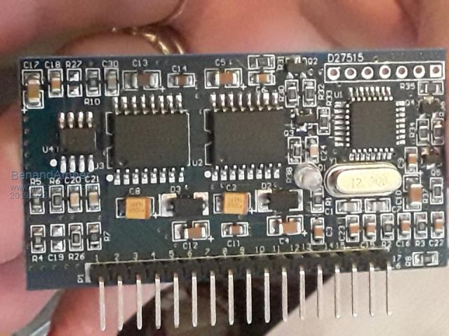 This is the esg002 that came in it and the original settings 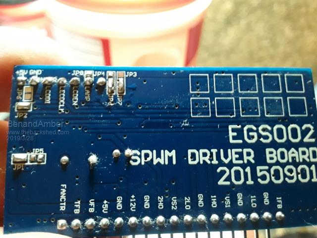 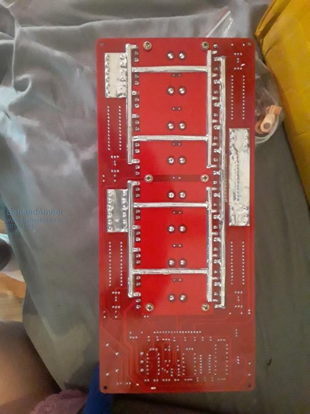 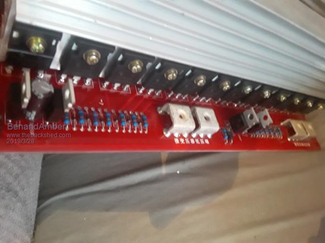 24 hy4008 be warned i am good parrot but Dumber than a box of rocks |
||||
| gadgetjack Senior Member Joined: 15/07/2016 Location: United StatesPosts: 127 |
That is the bigger brother of the board I got. Mine is 3000 watt and yours is 5000 watt. I have mine running right now. It does a good job if you don't go crazy with the load. Pick a good fan for it. |
||||
| BenandAmber Guru Joined: 16/02/2019 Location: United StatesPosts: 961 |
Gadgetjack thanks for your post I will be running 48 volt and using a 52-pound 5000 watt Transformer the spec sheet says that it is good for 10000 watt but who knows that might be Chinese watts at 60 volt it supposed to be good for 12000 Watts I was thinking about ordering a 48 volt case fan and hooking it up to the on switch of the inverter so that if the inverter is on it is on unless there's a reason why I shouldn't if you have any suggestions on what I should and shouldn't do with this board I'll be glad to hear from you there is probably a lot of other people that will be reading this deciding if they want to buy one of these boards or or not If and when I get it running I plan on documenting everything and giving the board a good workout I'm trying to make this post as informative as possible I plan on taking the 393 chip off and disabling all current feedback And adding zener diodes like poida mentioned on the little Chinese inverter board post thanks again be warned i am good parrot but Dumber than a box of rocks |
||||
| gadgetjack Senior Member Joined: 15/07/2016 Location: United StatesPosts: 127 |
I like the idea of a fan on when ever power is on. Makes sense. I did have to change the 50hz and modify for 110 volts ( they come as 220v as shipped ). That is just the feedback circuit. Good luck! |
||||
| Solar Mike Guru Joined: 08/02/2015 Location: New ZealandPosts: 1123 |
I think that board has a bunch of resistance links soldered to the pcb between two of the large terminals, these are used for current overload protection circuitry on the main board, so I wouldn't go chopping things off to hastily as you don't know how they have wired this up. Similarly if the drivers are running off 12 volts supply then adding extra zener's isn't required with the totem pole drivers fitted to that board. Cheers Mike |
||||
| BenandAmber Guru Joined: 16/02/2019 Location: United StatesPosts: 961 |
Solar Mike are resistance links where single core wire is put side by side like resistors Is the transistors on the edges of the board with no heat sinks called totem pole drivers and if so how do I tell if they are running off a 12-volt Supply I understand if you're too busy to deal with someone as ignorant to this stuff as I am but I'm trying to crawl walk and run at the same time seems the only way I can learn is to make mistakes Thank you for your time be warned i am good parrot but Dumber than a box of rocks |
||||
| BenandAmber Guru Joined: 16/02/2019 Location: United StatesPosts: 961 |
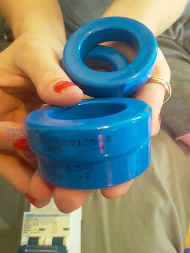 We are looking for some advice about what kind of filter should be on this board the manufacturer recommends these sendust torid core we allso have a E80 ecore 87 material we are going to be using this dc 100 amp breaker 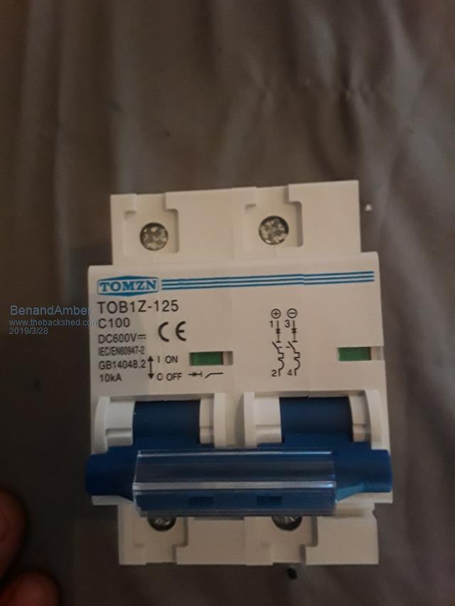 I also have this one made from a ferrite off of a old style television tube we have a inductance meter to check Henry  be warned i am good parrot but Dumber than a box of rocks |
||||
| Solar Mike Guru Joined: 08/02/2015 Location: New ZealandPosts: 1123 |
Yes. Board has a small switch mode power supply for the drivers, can only tell by switching it on The manufacture of this board has constructed a "System" all you have to do is connect it up as per their instructions, unless you are experienced, I wouldn't go snipping bits off it or modifying it. I have a smaller version of that unit with 20 mosfets, it worked fine, when I last tested it about 12 months ago. Mike |
||||
| BenandAmber Guru Joined: 16/02/2019 Location: United StatesPosts: 961 |
Thanks solar Mike or your comments I won't be changing anything unless someone like you tells me it's okay I am poor this was a lot of money for me Thanks again for your time be warned i am good parrot but Dumber than a box of rocks |
||||
| BenandAmber Guru Joined: 16/02/2019 Location: United StatesPosts: 961 |
gadgetjack it would be absolutely awesome if you would fill me in on how you changed it from the 220 to 110!!! what kind of filter did you build or buy for it and the 50 to 60 hertz is just on the card right? Thanks for your time I appreciate all of advice be warned i am good parrot but Dumber than a box of rocks |
||||
| BenandAmber Guru Joined: 16/02/2019 Location: United StatesPosts: 961 |
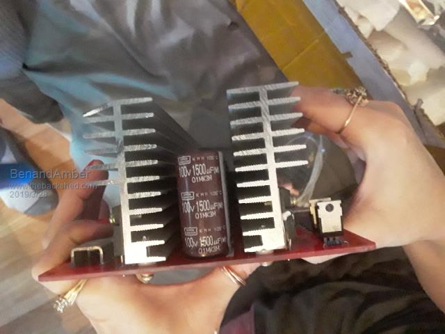
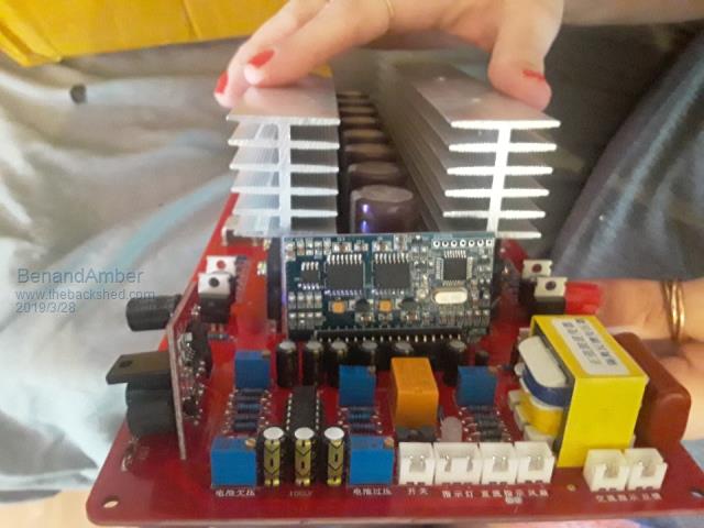
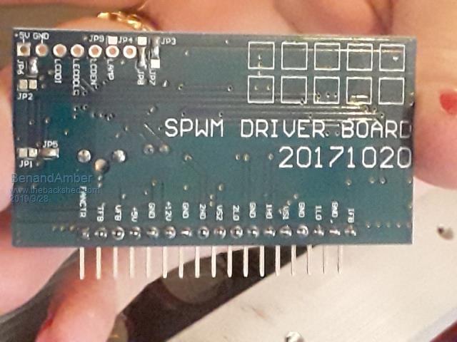 Sorry everyone I have several of these oo2 boards I posted a pic of the wrong one up above just the back though the front one is the right one this is the one that came with the board Notice that this does not have the little black wire soldered on maybe they fixed this problem in all the pictures they have a black wire soldered on the front of the card going down to the board I am not no expert by any means but this just seems very high-quality to me it's heavy it feels right in your hand it just looks like quality to me It's big the APC 3000 watt boards I have looked small compared to this one all of the solder points look perfect to me I wasn't expecting something this heavy and this high quality I may be speaking too soon and it might blow up the second I hook it up but me and Amber are very impressed with it so far I think the dead time is set for 500 is this a good thing if I remember correctly everybody says set them to 300 If anyone feels like explaining the cause and effect of the Dead time I would like to learn about it thank you everybody for your time be warned i am good parrot but Dumber than a box of rocks |
||||
| gadgetjack Senior Member Joined: 15/07/2016 Location: United StatesPosts: 127 |
I changed the jumper on the small board for 60 hz. I added the 2.7k resistor shown in the picture to bring the feedback into the 120 v range . I hope the picture is viewable. 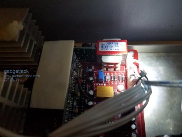 |
||||
| BenandAmber Guru Joined: 16/02/2019 Location: United StatesPosts: 961 |
Gadgetjack thanks for your post and your pic I will see if mine is the same If so you have saved me a bunch of guessing I appreciate it mine does not have the little black wire on little board what is that wire for if you have the time do you care to explain what kind of filter inductor you're using and tell us the things you like and dislike about the board for people that may be thinking about buying one If you are too busy I understand Thanks for your time be warned i am good parrot but Dumber than a box of rocks |
||||
| gadgetjack Senior Member Joined: 15/07/2016 Location: United StatesPosts: 127 |
I got my inductor from an old Xantrex inverter I parted out. Not sure what the black wire was for , never traced it out to tell you the truth. It just worked so I left it at that. Best of luck with yours. |
||||
| azhaque Senior Member Joined: 21/02/2017 Location: PakistanPosts: 117 |
https://www.aliexpress.com/item/Free-shipping-1pcs-1800W-5500W-DC12V-24V-36V-48V-to-AC-220V-pure-sine-inverter-board/326 37730780.html?spm=a2g0s.9042311.0.0.4pvcs8 Picture EGS002 driver board jumper Description: JP1: When JP1 link, JP5 is disconnected, 60Hz output; JP5: When JP5 link, JP1 is disconnected, 50Hz output; JP2: When JP2 link, JP6 is disconnected, 3 seconds soft start; JP6: When JP6 link, JP2 is disconnected, close the soft start. JP1 must be jumped and JP5 disconnected. This will make it 60 Hz. azhaque |
||||
| BenandAmber Guru Joined: 16/02/2019 Location: United StatesPosts: 961 |
Thank gadgetjack be warned i am good parrot but Dumber than a box of rocks |
||||
| BenandAmber Guru Joined: 16/02/2019 Location: United StatesPosts: 961 |
Thanks for the info azhaque be warned i am good parrot but Dumber than a box of rocks |
||||
| BenandAmber Guru Joined: 16/02/2019 Location: United StatesPosts: 961 |
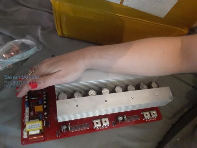
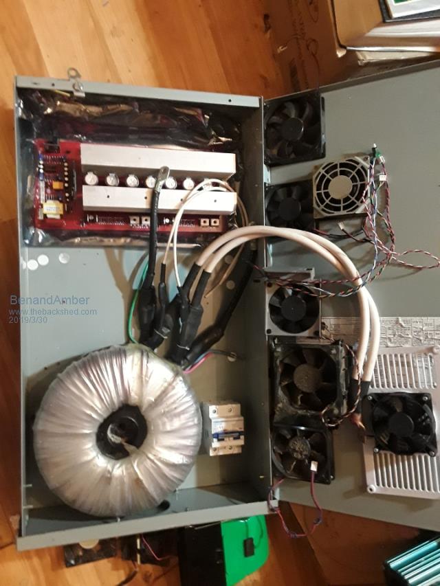 Trying to figure out the best placement for everything looks like I'm going to have to buy a set of crimpers to crimp new ends on the wires they're too long or may be solder them on The wires are also ginormous two wires for each and still 1/2 inch across I don't know which is the best way solder or crimp be warned i am good parrot but Dumber than a box of rocks |
||||
renewableMark Guru Joined: 09/12/2017 Location: AustraliaPosts: 1678 |
Hydraulic crimpers are fantastic, very cheap these days. Like this with 4-70mm sets of dies should do you fine. Try and mount that power board so the heatsink is vertical, that way the natural rise of heat will assist you. Fit the fan close below. Be aware that the air will take the path of lowest resistance, you may need some kind of a shrowd to direct air where you want it. No point it blowing all over the place, it needs to go through the fins to cool them and the caps. Cheers Caveman Mark Off grid eastern Melb |
||||
| BenandAmber Guru Joined: 16/02/2019 Location: United StatesPosts: 961 |
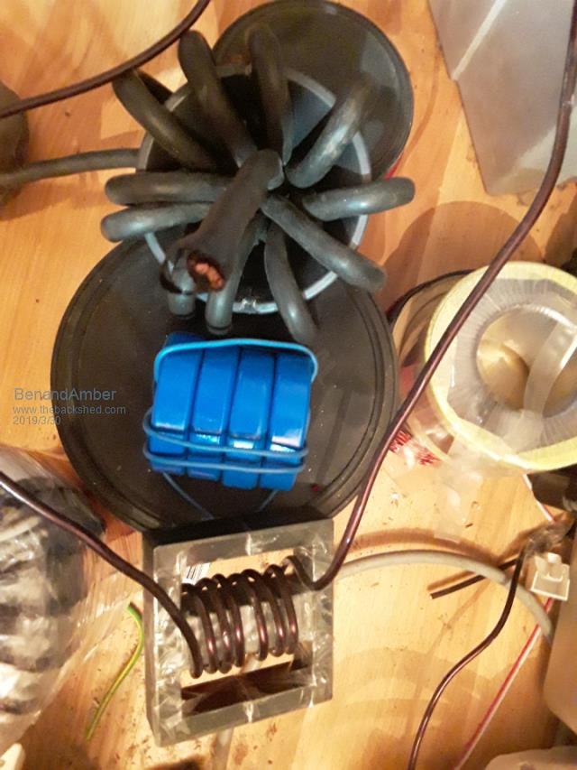 I have three choices for inductor filter The one on the left is the ferrite off the back of an old television tube The one in the center is 4 sendust toroid The one on the right is a e80 core I don't have any idea how I'm going to get enough turns on center one or the right one and don't know if the left one will work I've never heard anybody using this type of material be warned i am good parrot but Dumber than a box of rocks |
||||
| Page 1 of 5 |
|||||
