Notice. New forum software under development. It's going to miss a few functions and look a bit ugly for a while, but I'm working on it full time now as the old forum was too unstable. Couple days, all good. If you notice any issues, please contact me.
BenandAmber Guru Joined: 16/02/2019 Location: United StatesPosts: 961
Posted: 08:43pm 30 Mar 2019
Copy link to clipboard
Print this post
Thanks renewablemark I will try to get those I dream about boats seems like I read somewhere that you have a boat
Thanks again for your timebe warned i am good parrot but Dumber than a box of rocks
BenandAmber Guru Joined: 16/02/2019 Location: United StatesPosts: 961
Posted: 08:10pm 31 Mar 2019
Copy link to clipboard
Print this post
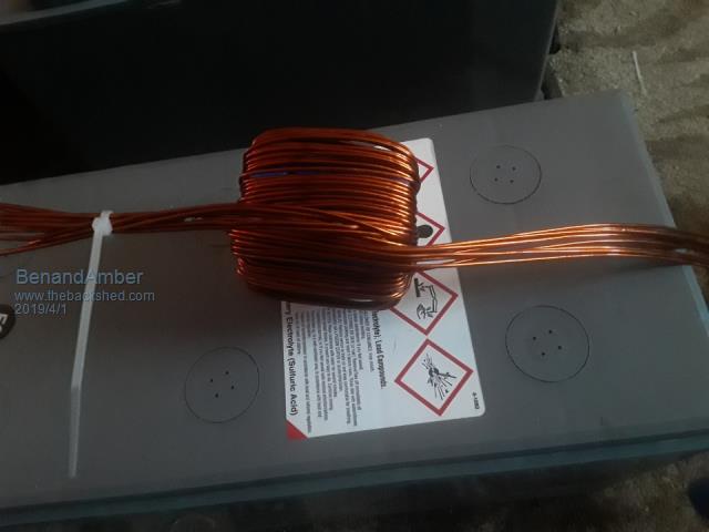
F4
Ten in hand 14awg seems kind of small to me
still really hard to wand on those small toroids
chassis wiring guide says 32 amps four 14 awg
So with temperature rise should be good up to 320 amps
My Transformer is 5,000 watts this will be the upper limit of what I'll be runningEdited by BenandAmber 2019-04-02be warned i am good parrot but Dumber than a box of rocks
tinyt Guru Joined: 12/11/2017 Location: United StatesPosts: 431
Posted: 01:52am 01 Apr 2019
Copy link to clipboard
Print this post
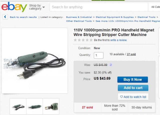
I used the same approach: multiple small diameter wires (awg 19) for the toroid primary and chokes.
Because I will be stripping hundreds of wire ends, I bought and used something like this.
BenandAmber Guru Joined: 16/02/2019 Location: United StatesPosts: 961
Posted: 05:18am 01 Apr 2019
Copy link to clipboard
Print this post
That is awesome tinyt A great idea
My wife said she's buying appliances for the RV before I buy anything else
happy wife happy life
So I guess I'll have to use a little rotary tool for now
I appreciate all your good ideas and input thank you
By the way I got the little China board up and running
I have already posted about it put pictures up
Never would have happened without all the good advice you guys gave me along the way
Highly appreciate itbe warned i am good parrot but Dumber than a box of rocks
BenandAmber Guru Joined: 16/02/2019 Location: United StatesPosts: 961
Posted: 05:23am 01 Apr 2019
Copy link to clipboard
Print this post
I would like to use the ferrite off the back of big television tubes
would like to know if any of you guys think it will work
If so I might do some testing with the little China board
I am looking forward to blowing it up again
So isn't my 11 year old son he was very disappointed today when the little China board ran and didn't blow up again
He started working on a little amplifier circuit to amplify music from his phone
I think it'll be a good hobby to keep him out of troubleEdited by BenandAmber 2019-04-02be warned i am good parrot but Dumber than a box of rocks
Revlac Guru Joined: 31/12/2016 Location: AustraliaPosts: 961
Posted: 06:24am 01 Apr 2019
Copy link to clipboard
Print this post
I did try a ferrite yoke out of an old TV some time ago and it did lower the idle current just a little, I think. At the time I only had basic amp meter, voltmeter and no scope to see the effect it had on the waveform, only had one yoke to try as all the rest were 2 piece's.Edited by Revlac 2019-04-02Cheers Aaron Off The Grid
BenandAmber Guru Joined: 16/02/2019 Location: United StatesPosts: 961
Posted: 07:48pm 01 Apr 2019
Copy link to clipboard
Print this post
Reviac
I really appreciate you posting some info on this matter
I have no scope but I think I'm going to try it
you just gave me enough confidence to do so
Thank you for sharing your knowledge
Tinyt boy would have been really nice to have one of those machines you pointed out
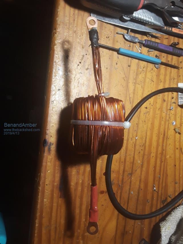
I put ends on that inductor took me forever and a day to get all them wires done but I did get it done and then I coated it in resin so hopefully it won't be noisy Edited by BenandAmber 2019-04-14be warned i am good parrot but Dumber than a box of rocks
BenandAmber Guru Joined: 16/02/2019 Location: United StatesPosts: 961
Posted: 04:35am 24 Apr 2019
Copy link to clipboard
Print this post
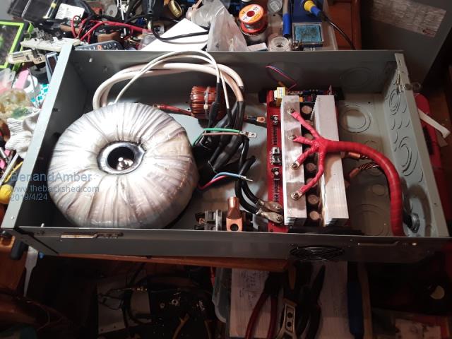
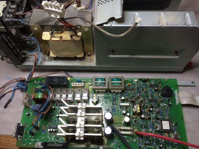
The wire on the low side primary is2 AWG and it has two of them on each side
the wire on the high side secondary of the Transformer is number 6 AWG and there's also two on each side
wire coming in from the batteries is 0/3 it's copper good for well over three hundred amps
it's what was left over from a large commercial building install it is very hard to bend have to have cheater pipes and I'm not a little guy
Believe it or not the biggest problem I am having is the design process wish I would have thought it out a lot more I'm used to bend and wire and tight places this is a whole another Ball Park
I went ahead and ordered a large 48 volt fan it will be on the top sucking hot air out
i have a small 12 volt fan plug straight into the board it's on the side there in the picture and it'll be kicking on and off by the board
I've seen a lot of inverters on this site that looks a whole lot better just a little bit jealous
I've never designed and built an inverter before so I don't think it's too bad for a beginner
yeah I'm talking about you warp speed yeah renewableMark you too clockman France and a lot of others on this list of jealousy I could go on and on hey I just about forgot tinker
give me another 5 or 10 years maybe they'll start looking a little better
All jokes aside really really impressed with a lot of the inverters I see on hereEdited by BenandAmber 2019-04-25be warned i am good parrot but Dumber than a box of rocks
azhaque Senior Member Joined: 21/02/2017 Location: PakistanPosts: 117
Posted: 01:12pm 24 Apr 2019
Copy link to clipboard
Print this post
BenandAmber,
Looking good. Have you fired it up. Incidentally where is the temperature sensor. Would appreciate if you could take a photo.
Thanks
azhaque
BenandAmber Guru Joined: 16/02/2019 Location: United StatesPosts: 961
Posted: 05:59pm 24 Apr 2019
Copy link to clipboard
Print this post
Azhaque
I really appreciate your help and consideration
I know some people might not have a hard time finding information on this site but it's impossible for me
I'll try to do the searches at the top of the pages and get nothing
Really cool of you putting a link to the how to make a toroidal core information
I knew I'd read it somewhere but looked and looked and could not find it
Even found a link on YouTube to a guy that makes Square Transformers in Pakistan out of remanence like you was talkin about
Seems like a pretty smart dude by the way yeah it's really nice batteries and an awesome Transformer he made himself
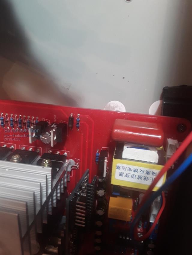
Sorry for rambling on the heat sensor is right behind the little ESG 00 2 bored attached to the front of one of the heat sinks
it's the little grey thing
I have not powered it up yet waiting on a few wire connectors to come in to finish wiring it up
I also am not very happy with the choke that I made for it I may be building a larger choke
when I do fire it up it will be on video for all to see in case of it blowing sky-high Edited by BenandAmber 2019-04-26be warned i am good parrot but Dumber than a box of rocks
BenandAmber Guru Joined: 16/02/2019 Location: United StatesPosts: 961
Posted: 06:14pm 24 Apr 2019
Copy link to clipboard
Print this post
I would like to let everybody know that I have a little bit of a learning disability
If I forget your name or get your mixed up with someone else I'm very sorry
I seen a lot of inverters on this site and I am just overwhelmed how absolutely perfectly they are designed laid out and made
that's what I strive for monkey see monkey do
you guys know who you are I'm sorry if I get your names wrong or forget to include your name like tinyt designing his own board and many othersEdited by BenandAmber 2019-04-26be warned i am good parrot but Dumber than a box of rocks
hary Regular Member Joined: 15/04/2019 Location: FrancePosts: 89
Posted: 06:58pm 24 Apr 2019
Copy link to clipboard
Print this post
Hi BenandAmber.
I don't think you provided a link pointing to where you get your power board from.
Would it be possible to have it please.Edited by hary 2019-04-26
BenandAmber Guru Joined: 16/02/2019 Location: United StatesPosts: 961
Posted: 09:27pm 24 Apr 2019
Copy link to clipboard
Print this post
I don't have a link eBay sells them and AliExpress sells them
they're a little hard to find on eBay they are there on eBay it's $150 for this red board
AliExpress it's around 168 I think if I remember correctly I bought mine off of AliExpress and not too long after I bought mine eBay started selling the exact same one
The little 4 mosfet inverter board on my other post named little Chinese inverter board is sold on eBay and AliExpress also and it runs a little under $30 bucks
this big one I haven't got running yet but if it's anything like the little $30 one then it's going to be awesome
Please take note that I do not run them like they came I do the modifications that poida the Great instructed me to do on my other post called Little China inverter board
I have no experience on how they run without the modification but from what I read and hear they blow up
the modifications are very easily done if you do exactly as instructed I learned that one the hard way
I did have good luck at changing the original mosfets that came with the little China inverter board to Hy40 0 8
The large inverter board shown on this page came with the h y 4008 not saying that all boards that look like this one will come with them so you might want to check
And another thing you might want to talk to some of the more experienced people on this form but my little inverter board will do 2000w so 24 Hy 4008 might be just Overkill
If you get really lucky like I did one of the greats might take you under there wing So try to make a friend or twoEdited by BenandAmber 2019-04-26be warned i am good parrot but Dumber than a box of rocks
hary Regular Member Joined: 15/04/2019 Location: FrancePosts: 89
Posted: 10:16pm 24 Apr 2019
Copy link to clipboard
Print this post
Thanks Ben.
I've just finished reading your other thread "Little China inverter board".
I've also seen the modification instructed by poida, despite I don't understand why the board needs that modification !
I don't have toroid at hand but have old UPS that I was thinking to hack for my inverter purpose.
Might be a good start with this little chinese inverter board.
BenandAmber Guru Joined: 16/02/2019 Location: United StatesPosts: 961
Posted: 05:22am 25 Apr 2019
Copy link to clipboard
Print this post
It has something to do with a defect three things are trying to happen at the same time
when current overload happens and it makes it oscillate I probably got half that wrong but it's something like that
With modifications you just can't beat that under $30 board I don't know how it would be from the factory like I said I've never tried it
There is a video of a guy in the United States with a red board just like this one of mine and it oscillate and blows up on him several times and he finally gave up
be warned i am good parrot but Dumber than a box of rocks
azhaque Senior Member Joined: 21/02/2017 Location: PakistanPosts: 117
Posted: 08:30am 25 Apr 2019
Copy link to clipboard
Print this post
Thanks for the photo BenandAmber.
Encouraged by your build I ordered one myself. So I am mentally planning the build.
The reason I asked the question about the temp sensor and whether you have fired it up yet, is because I believe the fan is likely to run continuously because of a small flaw in the egs002 board. You have reported the issue in the other smaller inverter that you have built. Luckily the solution is fairly simple. Its just soldering a fixed value resistor under the board, to get the fan to start at a particular temperature.
In this bigger board, of which you have posted the photo, things are easier in terms of fixing the issue. Since it doesn't have that black flying lead from the main board, the egs002 can be removed for testing. What we need to know are the specs of the NTC sensor in the photo. The application notes indicate that the NTC resistor is of the type that has a value of 10K @ 25 degC. The application note says that a 10K resistor will cause the fan to come on at 40 degC.
So hopefully your firing up and the arrival of my board from China should coincide. What you learn from firing up of the board will be of immense value for me in building my inverter.
Salaams to you and your family.
azhaque
azhaque Senior Member Joined: 21/02/2017 Location: PakistanPosts: 117
poida Guru Joined: 02/02/2017 Location: AustraliaPosts: 1388
Posted: 09:12am 25 Apr 2019
Copy link to clipboard
Print this post
Harry, I suggest we modify these boards to prevent 2 things from happening.
First thing is easy to understand. The MOSFET's gate pins are driven by IR2110 IC gate drive chips. These have outputs that are specified to never have voltage below -0.3V to ground on the low side output, and -0.3V to VS on the high side. I have observed voltages on MOSFET gates far in excess of these -0.3V, due to dv/dt effects. It is my theory, not prven by facts and reproducible evidence, that this dv/dt generated gate voltages, when fed back to the IR2110 via the diode, (including the diode voltage drop), kill the IR2110, then when dead, the MOSFETS fail, with sparks, smoke and everything. To prevent this, I suggest 15V TVS diodes, from gate to source. This will clamp dv/dt induced voltages to the TVS diode drop voltages, about 0.4 or 0.5V. Not anything like the 2 to 3V seen on my bench.
Second modification is to remove the "high speed" over current cutout. IR2110 IC have a shutdown pin, which when driven to be in effect, immediately shuts down the gate drives, both low side and high side, to zero volts. This happens in a few hundred nanoseconds. It might seem all is OK. But this same high speed shut down can also re-enable the outputs in a few 100 ns. And so there is the possibility that the MOSFET full bridge will be switching on and off, really hard, producing huge current transients that are sent through the load (big transformer). I have had on my test bench the situation where this high speed shutdown has made the toroid nearly jump up off the bench. (I exaggerate..) I prefer to disable this. I do this by removing ALL high current shutdown function from the EGS002.
There is still some over current protection. I prefer to have a relatively slower acting device. A high current DC contact breaker, I place this in series with the DC supply.
In use, the HY4008 can deal with very large current spikes without failure. The specifications show 800A "pulsed current" and 200A continuous. Good luck dissipating the heat from 200A. The point is that these can handle huge short term current peaks OK. But if we turn it on and off via external means (shutdown pin) in very short but high energy yielding pulses, we can blow them ourselves. It is best to let them handle a steady load.
What kills them is heat, from long term running under high current and insufficient cooling, or cross conduction due to failed gate drive IC outputs.
My preferred build of an inverter using the Chinese boards is to disable all over current functions, add TVS protection to the IR2110 outputs and use a sensibly sized DC contact breaker on the supply. And have a good working fan to blow on the too small heatsinks.
If you choose to make an inverter, you will need a good primary winding inductor, about 50uH and it is best if they are Ferrite. We have explored the types of inductors here elsewhere. I prefer the biggest E type Ferrite from TDK. About $20 from RS components.
Time to cook dinner...
Edited by poida 2019-04-26wronger than a phone book full of wrong phone numbers
BenandAmber Guru Joined: 16/02/2019 Location: United StatesPosts: 961
Posted: 02:46am 26 Apr 2019
Copy link to clipboard
Print this post
Yeah exactly what he said
Thanks for clearing that up poida the great
I hope you and your family are doing well and I'll never forget what you've done for me and my family
And since I've got you here is all current functions shut down on my board
Or do you suggest I do more to the big board done exactly what you told me to do in the Little China board post to all of my China boards
The reason I'm asking is I'm getting ready to fire up the big one here soon and didn't know if it would be any different from the little one
You can only give advice if someone messes up it's on them not you!!!!
Everyone on here is so very careful with the advice they give
I cant understand why they would think it's their fault when someone else messes up
And be so humble when everything goes exactly as planned
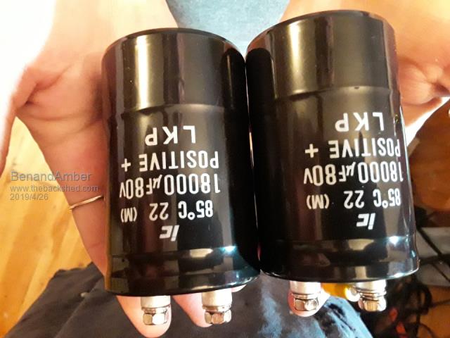
By the way I am very very happy with the little inverter did you see them big capacitors I installed in it
I know four mosfets shouldn't be powering a small air conditioner and big circle saw box fan and lights and whatever other tools I happen to be using at the RV at the time
But you was exactly right by saying these things are bulletproof when you set them up exactly the way you say
I know it won't be able to dissipate all that heat one day and we'll blow
I put the biggest case fan in there as close to the heatsinks as possible and it runs constantly never shuts off
It's been like the Energizer Bunny so far but I'll keep everybody updated
be warned i am good parrot but Dumber than a box of rocks
BenandAmber Guru Joined: 16/02/2019 Location: United StatesPosts: 961
Posted: 03:05am 26 Apr 2019
Copy link to clipboard
Print this post
Azhaque
I am sorry I just seen your last post
I haven't had any temperature sensor problems
someone else was texting about it and I said it would be nice to know how to make it come on at a lower temp
I don't even know the temp that it comes on at
If I remember correctly I read somewhere that poida the great said it was fine the way it is
So I haven't given it any more thought I am using it exactly the way it is in my big inverter build with a really low amp fan
And I will be putting a very large fan on the top of the case that will run all the time it will be powered off of the battery input so if the inverter is hooked up it will be on
I will try to post everything I do and I do take videos of everything I do just in case something blows
I know absolutely nothing the only reason I have a up and running inverter is because of Poida the great and others on here telling me what to do
I have a lot of determination
Jack of all trades ace at few
everything I have ever tried in life I have became at lest a jack
With one exception Electronics
I've came to the conclusion that it's not something you can become a jack at in a year or two
it takes years and years of learning 2 become a good Jack and a lifetime to become an ace
Just my opinion on it bless you and your family my friendEdited by BenandAmber 2019-04-28be warned i am good parrot but Dumber than a box of rocks