
|
|
Forum Index : Electronics : Nano Power Inverter - Roll Your Own Style
| Author | Message | ||||
| poida Guru Joined: 02/02/2017 Location: AustraliaPosts: 1389 |
here are a few versions and I added a #define to permit easy change to the soft start ramp time. #define SSTIME 100 // how many 50Hz full cycles for soft start ramp I tried it with 50 and it made the toroid growl. There is no limit to the size, just keep it below 32000 (which would give it a 10 minute long soft start) if you make it = 1 and it would be a hard start and I do not recommend that. nano_1_v5_sync_pid_50Hz_update_20kHz.zip nano_1_v5_sync_pid_50Hz_update_40kHz.zip nano_1_v5_sync_pid_50Hz_update_25kHz.zip nano_1_v5_sync_pid_50Hz_update_50kHz.zip wronger than a phone book full of wrong phone numbers |
||||
| poida Guru Joined: 02/02/2017 Location: AustraliaPosts: 1389 |
And here is the 20kHz PWM version above with a trim factor that puts a DC bias on the output. I would only use values between -4 and 4 and start off with zero. Going from -1 to +1 gives a clearly seen peak in primary current at either zero crossing point. So a little goes a long way. Got a DC clamp meter? Useful to see and confirm the output trim Got a spare Hall current sensor? Put it in circuit in the primary, between FET bridge and inductor. nano_1_v7_balanced_mike.zip The part to alter is the first line in the code. // // PHASE_TRIM is a fractional change applied to one of the 1/2 cycles // to balance the inverter output. // For my test inverter, I use -1 // // This minimizes the DC current passing through the primary winding circuit // The more DC current there is, the more audible hum and a little // extra ineffeciency. // // safe range for this is -4 to 0 to 4. A DSO with a current sensor on the primary // is required to chose the best value. A DC clamp meter that resolves 0.01A is // also good. // Start with 0 and choose values that reduce the zero crossing peak current // when stable and at the set point AC output voltage. // The DC clamp meter is also used to choose values that minimize the DC current when stable // Ya don't need much to make a difference. // #define PHASE_TRIM -1 // // wronger than a phone book full of wrong phone numbers |
||||
| poida Guru Joined: 02/02/2017 Location: AustraliaPosts: 1389 |
I used the above trim code make the toroid hum during a fast soft start. Dark Blue is AC output voltage Pink is primary current Yellow is 50 Hz sync pulse 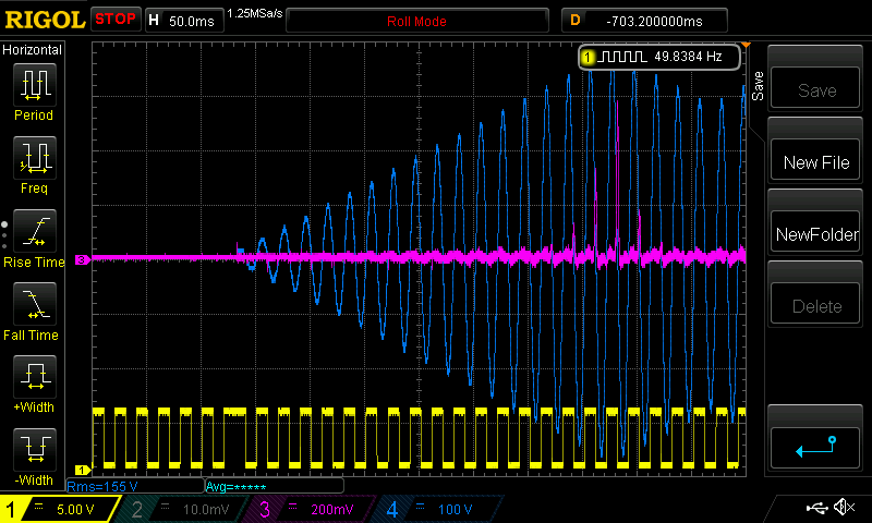 We can see a sudden increase in current near the end of the start ramp. This causes the noise. What causes the current increase? The output voltage is under the influence of the low pass filter on the feedback voltage. So there is some oscillation of output V AC Most of theses current pulses occur before output AC reaches setpoint so it can not be resulting from the slowed control loop + oscillation. I use the filter in this code since WG needs the filtering in his design. The nanoverter build includes an active filter on the feedback voltage and so does not need the digital filter as well. wronger than a phone book full of wrong phone numbers |
||||
| poida Guru Joined: 02/02/2017 Location: AustraliaPosts: 1389 |
and here I can show what -2 and +2 trim does to my test inverter. first -2 trim 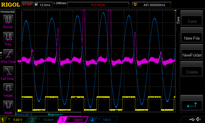 The primary current pulses coincide with negative going zero crossing of the AC output. next +2 trim 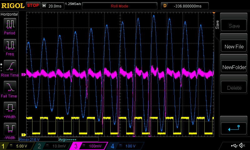 They now coincide with positive going zero crossing. In both cases the toroid makes loud hum during this time. When I revert to zero trim, the toroid is nearly silent as in the above video wronger than a phone book full of wrong phone numbers |
||||
| wiseguy Guru Joined: 21/06/2018 Location: AustraliaPosts: 1000 |
Peter, thanks for the modified codes, explanations and the CRO shots are brilliant. When you say phase trim, how does that work, is it a slight offset to the look up table addressing by shifting it + or - by a bit or two relative to the other 180 degrees? The other way I can imagine it is using a tick offset or two after reading the table. The effect is very graphic on the CRO - I didnt realise a DC clamp meter would give meaningful results on an AC waveform, I thought its sampling rate would cause aliasing and it would just give gibberish - I will try it at my first opportunity. I haven't even opened the new codes you sent me yet, I just saw your latest posts and curiosity got the better of me re the phase trim. If at first you dont succeed, I suggest you avoid sky diving.... Cheers Mike |
||||
| poida Guru Joined: 02/02/2017 Location: AustraliaPosts: 1389 |
The trim is added as clock cycles to one of the half waves. This addition only happens if the pwm width is greater than 5 clocks. So we are seeing +/- 2 timer cycles, which are 8 Mhz (Arduino timer clock is 1/2 system clock) wronger than a phone book full of wrong phone numbers |
||||
| wiseguy Guru Joined: 21/06/2018 Location: AustraliaPosts: 1000 |
Finally got to have a play after tea. Partly dismantled inverter to fit heavy copper link that was accessible for current probes & meters etc. I zapped a nano with the 25kHz code and start up setting of 200. Dc current was exactly the same as the 19.2kHz version ~ 17.5W idle. But the grunt was still there, so after fitting the link I did the DC current measurement of the primary drive. I just posted a video of a startup showing the -750mA DC offset at the grunt which quickly reduced & settled to +70mA over ~ 10 seconds. When I turned off the run switch and it was ramping down I restarted it when there was ~ 20% of soft stop remaining and it quietly rose back to ~ +70mA no grunt. I still maintain that there is something very different between ramping from a soft stop that is allowed to finish before restarting compared to a restart that occurs just before soft stop is finished. Although the restart, before soft stop ramp is finished, truncates the soft stop and it restarts the ramp up from zero, it is slightly slower and there is no grunt or large DC offset, just the +70mA with no overshoot. I'm not asking for this to be fixed (but if you feel inspired thats ok too), I'm just reporting a finding - I think it is highly unlikely I will be able to find the issue unless I trip over it accidentally. But it wont stop me from trying lots of code tweaks tomorrow in an effort to track it down. Even making it worse is probably a good result as it may lead me towards a final solution. If at first you dont succeed, I suggest you avoid sky diving.... Cheers Mike |
||||
| wiseguy Guru Joined: 21/06/2018 Location: AustraliaPosts: 1000 |
After spending time trying various software mods and making little headway today I am going to try a different tack now and use a more standard voltage feedback, I will still use the small 2mA/2mA isolation transformer, but with active full wave rectifiers and a gain section. I want to eliminate my active sample and hold section currently employed in the feedback loop to see if it improves performance (taming the grunt). Having a servo closed loop system, makes it very difficult to assess performance of circuitry and to pinpoint what is cause and what is effect, so in my quest to find the culprit it is next on the list to tackle. If at first you dont succeed, I suggest you avoid sky diving.... Cheers Mike |
||||
| Warpspeed Guru Joined: 09/08/2007 Location: AustraliaPosts: 4406 |
A multi pole active low pass filter with a suitably chosen cut off frequency can be used to reduce ripple after the rectifier. It can be made to correct faster, and have a lower final peak to peak ripple than the usual resistively loaded capacitor. Cheers, �Tony. |
||||
| poida Guru Joined: 02/02/2017 Location: AustraliaPosts: 1389 |
It's not the result of the closed loop control. The grunt occurs during open loop running. Running form zero pwm width to approx 80% width, rising monotonically. My view on the cause of the toroid grunt is that it's from non-linearities in the toroid core's behaviour. That the core is not behaving as we expect. By all means alter the closed loop system in many ways you can. But since it is not in effect during the period of time when the grunt occurs I can not see how that work could help. I will make a lengthy post later describing the non-linear or non-ideal behaviour of the toriod's iron core. wronger than a phone book full of wrong phone numbers |
||||
| poida Guru Joined: 02/02/2017 Location: AustraliaPosts: 1389 |
A toroid transformer has a characteristic curve that shows the magnetising force verses the resulting magnetic flux density. 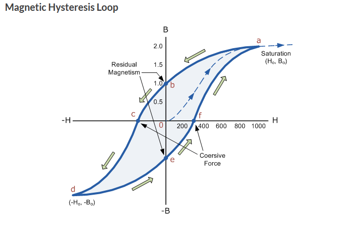 We all have seen this before. I like to view H as the current flowing in the primary winding. B is magnetism in the core. (or magnetic flux) After a high power thump of DC, due to a failed inverter power board the core will now be altered. It probably will have some residual magnetism. I also think the core will also have altered B-H curves for some of the micro-domains. The alteration will mean some domains will permanently retain some magnetism to some degree 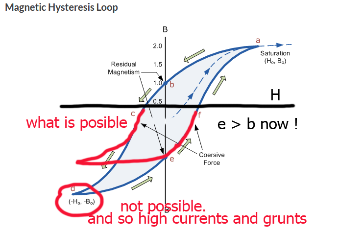 Note that the H axis is shifted UP from it's previous zero location. This reflects the permanent magnetism within the core. With the shift upwards of the H axis, the amount of current needed to take the core into saturation is less and it reaches saturation earlier in time. And so it spends more time saturated to a large amount, presenting a high current load to the power board. And emitting the grunts. Since we can have large current spikes during one zero cross and not have them during the corresponding return crossing I am forced to think that the core is presenting a different load to the applied voltage coming out of the inverter board for the two zero crossing events. This is why I describe it as non-linear. Maybe I should say non-ideal? Examples of the large current spikes were given in a previous post https://www.thebackshed.com/forum/ViewTopic.php?FID=4&TID=11384&LastEntry=Y#176583#176519 The remenent magnetism resulting from hysteresis is not to be confused with the small proportion of core micro domains that have now a permanent magnetic field to some degree resulting from the power board failure and subsequent large DC current pulse. I am also open to the idea that the entire core may have non symmetrical B-H curve slopes now, also resulting from the DC current pulse. I probably dropped a few clangers here. Sorry. wronger than a phone book full of wrong phone numbers |
||||
| wiseguy Guru Joined: 21/06/2018 Location: AustraliaPosts: 1000 |
Poida, before you go to too much extra trouble I would like to clarify what I think may be happening. As the loop enters bang bang control during ramp up I am concerned that perhaps my sample/hold circuit may not behave in a predictable absolutely linear fashion. Once under PID when the sample/hold is operating over a steady input level with only minor changes between loaded and unloaded it appears to be rock stable. However, how it behaves during the constantly changing nature of the bang bang control during the later part of ramp up is something I cant predict or prove hence wanting to eliminate it as suspect. Looking at the code and my feeble understanding of it, it appears that if the inverter is allowed to shut down after waiting for soft stop to expire and the FET driver enable changes state (disables), next time it starts. the code enters through an initialisation section. It appears though that if I do a restart whilst soft stop is in progress it may bypass the initialisation section & this is when I dont get the "grunt" - please confirm if that is the correct analysis. Whilst I agree about your other comments re transformer remanence etc, due the fact I can restart my soft stopping inverter and never have the grunt I am not convinced that remanence is causing my problem. It is still unknown and a work in progress and I'm prepared to admit maybe my controller could be suspect or contributing to the problem - time will tell. Tony thanks for the comments, my nano pico controller has the low pass two pole filter built in but I havent sent it out for manufacture yet. I will be trying my feedback control with out the low pass filter initially and may just wait for the new controller instead of hacking a filter onto the current unit, it will already have enough hacking to make the current changes to the V feedback.. If at first you dont succeed, I suggest you avoid sky diving.... Cheers Mike |
||||
| Warpspeed Guru Joined: 09/08/2007 Location: AustraliaPosts: 4406 |
Can you somehow find a way to trigger your CRO on the Grunt ? Then look at the various events immediately prior and during Grunting. Cheers, �Tony. |
||||
| wiseguy Guru Joined: 21/06/2018 Location: AustraliaPosts: 1000 |
Tony, Ive spent many hours trying to capture something meaningful with the CRO, the closest I got to anything identifiable was looking at the input current which has a surge upwards briefly during the grunt. The other factor is that the ramp time after restarting during a soft stop appears to be shorter, even though the ramp up still starts from zero. There is also the surge of up to ~1A of DC offset on the primary winding at around the grunt area of interest. They are the only anomalies I can see at the moment. Now I have a link where I can more easily attach current probes to monitor the primary current, when I finish my hacking of the feedback circuit, I will go searching again. Having a compact inverter is great, working on and probing parts of a compact inverter "sucks" - that is a technical term...... The parts I want to probe etc are usually the hardest bits to get at. If at first you dont succeed, I suggest you avoid sky diving.... Cheers Mike |
||||
| Warpspeed Guru Joined: 09/08/2007 Location: AustraliaPosts: 4406 |
Murphy wrote some of his famous laws around those kinds of problems. Cheers, �Tony. |
||||
| poida Guru Joined: 02/02/2017 Location: AustraliaPosts: 1389 |
The code works as follows: Each time through the control loop in check_switch_cont() a test is made. If nano pin D8 is LOW, then initialisation will be executed the next time D8 goes HIGH. I foresee a situation where you start it and mid way through ramp up you then stop it. At this point in time there is a significantly sized AC current waveform in the primary. Now you pull D8 LOW, to stop the inverter. This will only be sensed during the run through the control loop and that happens at 50 Hz. So eventually the next control loop is executed, maybe 20ms after you drive D8 LOW and two variables are set. oen = 0 now, so the ramp direction will be down in power. init_done = 0, to enable the call to init_vars() when the time comes. And the power continues to ramp down if D8 is kept LOW. If we wait long enough, the ramp down will get to zero power and stay there. When we interrupt the ramp down, mid way down to zero power, by pulling D8 HIGH we are starting the inverter. Since init_done = 0, upon inverter start we will execute init_vars() once and record that is has be executed to prevent repeated execution of this code init_vars() will set sst = 0 and that will set output power to zero immediately after the next run through the control loop. This is where you could have a large and sudden discontinuity in primary current or power. In summary: start it up, let it run for a few seconds or weeks or years. Stop it when you want. Do not interrupt the stopping process All good If you have it running, in either ramp up or stable under PID then stop it BUT DO NOT ALLOW IT TO STOP COMPLETELY, then resart it there will be a discontinuity in output with growls etc from the toroid. wronger than a phone book full of wrong phone numbers |
||||
| poida Guru Joined: 02/02/2017 Location: AustraliaPosts: 1389 |
here is the excel file I used, have fun. nanoverter ramp up.zip wronger than a phone book full of wrong phone numbers |
||||
| wiseguy Guru Joined: 21/06/2018 Location: AustraliaPosts: 1000 |
Thanks for the code explanation - it wasnt clear (due to my (in)ability to read code whether it went through init vars from an interrupted soft stop. Now I need to use the same emphasis you did so I know it cant be wrongly interpreted - please dont hate me THE INVERTER NEVER GROWLS FROM AN INTERRUPTED SOFT STOP despite the interrupted decaying envelope that was rudely interrupted. IT ONLY EVER GROWLS FROM A COMPLETE START UP either from cold or after running quietly and then a full soft shutdown followed later on by a restart. If at first you dont succeed, I suggest you avoid sky diving.... Cheers Mike |
||||
| wiseguy Guru Joined: 21/06/2018 Location: AustraliaPosts: 1000 |
Progress report. After building the active rectifier amplifier circuit I decided to bench test it all first. At idle there is a +15mV offset to the VFB pin of the nano and looking on a CRO there is about 50mV of noise. I tried capacitors all around the final op amp that appeared to be the culprit ie coupling + & - inputs with a small cap, decoupling the non inverting + pin to ground, neg feedback from output back to the - inverting pin all to no real effect. then out of desperation I tried a 1nF cap from the op amp output pin to ground and the noise vanished. To enable me to continue without soldering the capacitor onto the PCB I plugged a capacitor between pins 19 and 18 of the nano (which was not plugged in at the time) I reasoned that the 5V reference (pin18) was decoupled to ground solidly through 100nF and 10u and pin 19 was the Vfeedback pin what could go wrong. Suddenly my CRO greeted me not with the expected quieter VFB signal but a solid sawtooth waveform. It was only about 150mV p-p from memory and for all intents and purposes almost invisible at normal 1V per Div setting no wonder it was missed before. To cut a long story short the 10uF reference bypass cap was ineffective (- pin not grounded - not a soldering issue - Ill explain later) and the TL431 reference was oscillating. They can be quite unstable with ~100nF bypass only. I wonder what an oscillating reference pin can do to a micro that is trying to read an analog input to decide on PWM bang bang etc. I will decouple the final opamp output with 100R & 100n before applying it to the nano, the LM358 data sheet does not recommend capacitive loads of greater than 100p. Now Ill go put mains into it and see if it greets me with ~ 2.8V of feedback V. Edited 2021-10-26 16:26 by wiseguy If at first you dont succeed, I suggest you avoid sky diving.... Cheers Mike |
||||
| wiseguy Guru Joined: 21/06/2018 Location: AustraliaPosts: 1000 |
The saga continues unabated. Inverter has been reassembled and started a few times and I did a video of the Startup Rev1 The behaviour is essentially exactly the same. The startup time was set for 200 - by the way Peter thanks for the tweaks you added at the top for the various settings changes makes all this to-ing and fro-ing so much easier. The jump at startup can be seen to be ~ 0.9A which given the slowish analog meter could be somewhat higher than that. Next I decided to double the startup time to 400, the peak current (and grunt loudness) is tamed a bit better to ~ minus 0.35A max at the grunt but here I noticed something new, when I stopped the inverter I watched the clamp meter rise to ~ plus 0.35A towards the end of the ramp (ramping down). You can see it in the above video, despite the video startup setting of 200 not 400.. I am pretty confident this might be the smoking gun (apologies to AB), could it be that startup eventually adds to the remanence left during soft stop, until it saturates in one direction and the remanence is eventually neutralised by roughly an equal amount of energy that created it, causing the grunt ?? I dont have an answer to why it does not grunt during soft stop except that the energy is reducing instead of increasing and we are not saturating on soft stop, the energy is decreasing but also causing some significant remanence ? I also dont have an answer to the issue that if I enter soft stop and then interrupt it when the current is between 100 & 200mA when it next ramps up there is no grunt or discernible DC offset current greater than ~ 50mA. It has been an interesting endeavour to totally change the sample and hold feedback to a more conventional feedback and the behaviour is essentially identical to the previous method. The noise fix on the V reference seems to have made no discernible difference in the operation. Unfortunately/fortunately I have commitments for the next few days so I cant return to explore this further for now. It begs the question though why is there a significant DC current delivered to the core near the end of the soft stop. I have never noticed an increase in DC supply current on soft stop (usually it falls) but there is definitely an increase in DC to the toroid towards the end of soft stop. There is something weird going on here - I refuse to give up and just accept it I have to know and understand this phenomena that I am seeing. Peter can you fire up your test bed inverter and see if you get the same effect on soft start and full soft stop with your DC clamp meter - use the new code and set the time to 400. Also what happens with PID during soft stop ? can I assume that is disabled as soon as ramp down begins ? Edited 2021-10-27 00:18 by wiseguy If at first you dont succeed, I suggest you avoid sky diving.... Cheers Mike |
||||
