
|
|
Forum Index : Electronics : Nano Power Inverter - Roll Your Own Style
| Author | Message | ||||
Revlac Guru Joined: 31/12/2016 Location: AustraliaPosts: 1153 |
There is a fair bit of info to read and get through......Have to admit I got lost in the loong post several times,  computer screen is a bit small low res or something, never mind, printed the page from the link provide on the forum. computer screen is a bit small low res or something, never mind, printed the page from the link provide on the forum.  The aluminium mosfet mounting bar is Ideal for mounting external heatsinks, seen it used a few times and its very good method. I have looked at a few different inverters over time and found some similarities in the way they use there mosfet rating's, one had 4 200amp fets per leg, maximum amperage was also 200amp for the inverter, the same on some others, even 1 fet per leg on a high voltage stage inverter, IGBT was 80Amp and the maximum output allowed was around about 20amp. So it looks like they expect to run the mosfets at 25% of the rated power, not sure if many others follow that, I have not checked the Grid Tie inverters, but they don't need to handle surges as much. "The HY5608 FETs are rated at 80V and 360A at 25 deg or 250A at 100deg" so 4 fets per leg at 25%, should still get you in the realm of 300A, there is probably a better rule of thumb somewhere, but that seem very conservative. It looks almost as closely mounted as an SMD resistor, I Didn't see any diode parallel to the resistor for fast turn off, is it not needed with this gate drive arrangement or I missed that somewhere ? Cheers Aaron Off The Grid |
||||
| wiseguy Guru Joined: 21/06/2018 Location: AustraliaPosts: 1206 |
I did apologise in advance for the longish update so here is a post apology too (pun intended). Aaron I agree with your summary rule of thumb for the Mosfets. When you consider their static measurements of 200A or 300A the switching currents are a bit of a different beast. If you imagine a 50% duty cycle but average output current of 200A then the max switching current is 400A the minimum is zero, make the duty cycle 25% and we have 800A max. So in our inverter for a resistive load the peak current happens at the peak volts and PWM on time is max at that point. Keeping in mind phase shifts of reactive AC loads then our peak primary current must move from Vmax to further down the slope where the switching on times are reducing and therefore peak currents are rapidly increasing. If my analysis is wrong I or misleading I am happy to be corrected. It makes sense to me to have overkill in the FET rating ability, their max Power rating is another consideration and they quote 500W max, bigger is better. Lastly an update for the EG8010 controller. I put a unity gain precision rectifier between the little voltage sense transformer and the gain opamp and now it doesnt care about the phasing of the secondary. There is a 1.9V difference (234.9V - 236.8V) when I swap the transformer secondary windings phase. The small difference I'm sure is a minute difference between the 2 x halves of the opamps offset voltages - it is an LM358. The prototyping area came in real handy this time ! �So today I will get game and wire it into my inverter for a real test. Edited 2022-06-21 10:06 by wiseguy If at first you dont succeed, I suggest you avoid sky diving.... Cheers Mike |
||||
| Murphy's friend Guru Joined: 04/10/2019 Location: AustraliaPosts: 671 |
Mike, regarding your power mosfets and how many you need for 5KW, I did some testing with HY4008's a while back. Just 4 of them (one per leg) on an enormous heatsink could stand 1KW resistive load. They would blow if pushed beyond that power. So, for my dual stack single toroidal 5KW inverter I use 16 (4 per leg). These have stood up to any equipment I run here. Though my battery bank (20KW) is not big enough to run 5KW for more than a few minutes unless optimal sunshine is available to re charge it. Your "phasing of the secondary" comment has me puzzled, I never bothered about that. The inverter works  . . |
||||
| wiseguy Guru Joined: 21/06/2018 Location: AustraliaPosts: 1206 |
Hi Klaus, the comment refers to the EG8010 controller board I recently created and tested. It did not have a full wave system for the voltage feedback only half wave feedback processing. That is what they used in their data sheets but it relies 100% on the correct phasing of the inverter & feedback, in hindsight not error proof. I proved that on my unit by reversing the output sense connections. As I predicted it hated it ! So now I have incorporated a full-wave rectified feedback with no filtering, it works fine and phasing doesnt matter now. The Eg8010 only looks at the Peak at a 50Hz rate, I present it with 100Hz and it can choose whatever peak happens to be there at the required time. What I had 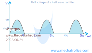 What I have now 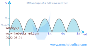 Thanks for the feedback about the FETs, given that the HY5608W FETs are ~80% more current at 25 degrees than the 4008's, in theory if the 4008's can handle ~5kW the new ones should be ok for ~9kW. Your comment about your battery pack now has me puzzled, if it is 20kWH why cant it run a 5kW load for 4 hours instead of a few minutes ? Maybe I misinterpreted something.... If at first you dont succeed, I suggest you avoid sky diving.... Cheers Mike |
||||
| wiseguy Guru Joined: 21/06/2018 Location: AustraliaPosts: 1206 |
Aaron, I forgot to answer your query about the lack of gate drive speed up diode across the series gate resistor. My current power board dont use them, you normally see them on series gate resistors around 4R7 - 15 Ohms. It helps to avoid shoot through by ensuring that in a half bridge, a Fets turn off is faster than the next Fets turn on. In single ended Power supplies it helps reduce the Fets dissipation, but there is often a resistor in series with the diode to control EMI & flyback MaxV which usually increases for fast switching, always trading off one issue against another. My gate rise and fall times with 12V is ~ 80-100nSecs with the transistor buffers & 2R2 series gate R. The anti shoot through capacitors on the inverse Optos ensures I already have ~ 400nS between turn off/on between top and bottom FETs so I have plenty of dead time without needing more speed up bits. The vertical resistor comment was actually mainly aimed at the components in the centre of the Power board, lots of vertical components there. If at first you dont succeed, I suggest you avoid sky diving.... Cheers Mike |
||||
| Murphy's friend Guru Joined: 04/10/2019 Location: AustraliaPosts: 671 |
Thanks Mike for explaining that 'phasing'. Back when I experimented with the EG8010 drive I always used a full wave rectifier which explains why I had no problems .You are right, theoretically my battery bank (lithium) could power a 5KW load for 4 hours but then the battery bank would be empty. Empty batteries are not much good to run my off grid house. So I keep the discharge manageable, just in case we get little sun for the next 2-3 days. Now, mid winter, remaining charge in the morning today shows 70% capacity, this usually gets topped up by midday or early afternoon. Only once so far this winter it only got to 98% full  . .With the price of these batteries I'm trying to get a long life out of them without being stingy with electricity use. Its just a question what to turn on when - easy for just the one old bloke living here . |
||||
| wiseguy Guru Joined: 21/06/2018 Location: AustraliaPosts: 1206 |
One of my reasons for making an EG8010 controller now was curiosity about how it would behave configured as nano style outputs using the inverse optocoupler drive for the power stage. The other reason is I wanted to try a totally independent new sine controller source in an effort to try to determine/prove if the "grunt" issue I have was emanating from hardware or software. The answer is that the grunt/growl from the transformers is still there, just as bad as it ever was with the Nano. My idling current is up from ~360mA to around ~410mA So to Poida an unreserved apology for suspecting it may be software related and a thank you for persevering with me in our attempts to effect a cure for the issue. I am going to sulk for a while, dust myself off and re-look at this with new eyes. After the controller and power output sections there are only 4 components, 2 transformers in parallel, a series choke and the mains rated capacitor that in this case is 4u7. I did something slightly different in my build I split the series choke into two half windings. They have a total of the same number of turns on the same core but they are two half windings one in series with each leg of the "H" output to the transformer. I will try a single choke to see if it makes any difference, this will take some time as it is buried under everything.  If at first you dont succeed, I suggest you avoid sky diving.... Cheers Mike |
||||
| wiseguy Guru Joined: 21/06/2018 Location: AustraliaPosts: 1206 |
I have played a lot more with the EG8010 & Nano controllers and observing the start up behaviour in my inverter With the EG8010 controller, the Grunt is there sometimes at various degrees of loudness & time but totally absent at other times, it it not predictable. There is no ramp down when you turn the inverter off (via pin6 of the 8010) so there is a good chance of remanence - residual magnetism in the core depending on where in the 50Hz it got clobbered. The Nano on the other hand always has the same grunt, but it uses a ramp down so I guess the magnetics starting point is always predictable & consistent (along with the grunt). Next I experimented with the Nano by injecting a fixed current in the secondary (240V winding) of the toroid, whilst the inverter was off using 1, 2, 3, 4 & 5 Amps with unipolar and then I tried reversing the currents, with a soft-stop/restart in between each test. I found that one current polarity causes minimal grunt and a faster settle after a restart. Polarising the core the opposite way increased the grunt many fold and had a longer settling time. The growl heading to the grunt also started earlier during the ramp up. Looking at the rise in input current during ramp up shows a steady slow almost linear increase of current up to around 60%-70% of max. but the current rapidly increases more exponentially at a fast rate for the remainder when the toroidal noise/grunt becomes evident. Using the Nano code I have though, never eliminated the grunt entirely which is slightly different to the 8010 results. So whilst I understand a little more about what is happening I still do not have a cure or explanation. Question for Poida: Peter, In the Nano code description I got to this part and have a query. Quote: Each 100Hz cycle of this closed loop code, - if it is in soft start mode, increase PWM duty% by 1/250, and stopping increasing when Vfb is greater than the setpoint or soft start has arrived at 100% duty cycle. While in soft start, if Vfb is greater than the setpoint, reduce duty% by 1/250. There might well be a period of time where the AC output is controlled by the soft start code only. This is a short period of time, in my testing it's maybe 1/2 to 1 second depending on the AC output voltage setpoint. - if it is not in soft stop mode AND it has been in soft start mode for 250 of these 100Hz cycles, then change over to PID control. Should this read: if it is not in soft stop mode AND it has been in soft start mode for 250 of these 100Hz cycles and VFB was achieved = to setpoint then change over to PID control ? My main question, if during soft start Vfb becomes greater than setpoint, what is wrong with truncating soft start and handing over to PID immediately ? I guess the blue line above may read: - if it is not in soft stop mode AND during soft start mode (<250 of the 100Hz cycles - else restart) it has achieved Vfb > setpoint, then truncate soft start mode and change over to PID control. If it is easy to implement I would love to try it - unless there is a verboten reason... Last comment, for ramp up and control, I used to advocate increasing the Sine amplitude with matched pairs of same size half sines for each step increase which is essentially a 50Hz rate. I suspect that with the existence of remanence, increasing at 100Hz (each half cycle) during ramp up might have a better result for the magnetics (smaller incremental increases with each successive increase helping to counteract the previous pulses remanence )? �It appears that 100Hz increases are implemented everywhere in the current code ? For ramp-up, maybe slowing the increase by doing it at every 3d or 5th half cycle especially after 50% of the ramp could help ?? ie initial ramp up % of 2/250 each zero cross should be fine, but at 50%+ of ramp, slowing % to say 0.5/250 for last part of ramp ? If you decide to call BS for any of the above, go ahead I can take it. �  Edited 2022-06-28 14:06 by wiseguy If at first you dont succeed, I suggest you avoid sky diving.... Cheers Mike |
||||
| Revlac Guru Joined: 31/12/2016 Location: AustraliaPosts: 1153 |
I have been using Pin 6 on the EG8010 for on/off, The turn off for the inverter with the EI transformer was silent and uneventful, the turn off for the inverter with the large C core is mostly quiet, occasionally it will have a small thud, barely noticeable over the sound of the switch itself, I must have turned that thing on and off over 100 times already. When I did one with a Toroidal transformer (not mine) It was a noticeable thump when turned off, I wouldn't say it always did that. BTW I do remember a friend had a small selectronic inverter, I was sure I heard that thing grunt at startup. I had always thought that silicon steel was not supposed to hold any magnetism, but maybe its not so. Cheers Aaron Off The Grid |
||||
renewableMark Guru Joined: 09/12/2017 Location: AustraliaPosts: 1678 |
I have been busy with a monster project so have not been keeping up with things on here. I seem to remember all sorts of interesting sounds on start up, they pretty much went away with a nice big iron choke. Have you tried that yet? Cheers Caveman Mark Off grid eastern Melb |
||||
| wiseguy Guru Joined: 21/06/2018 Location: AustraliaPosts: 1206 |
Hi Mark, good to hear from you again ! �I said earlier on that if I just put 50-100 milliohms in series with the transformer primary it became almost silent always, but that by itself is no answer. Using your suggested iron core would probably mute the problem grunt given the higher impedance/resistance involved. When you add the extra wire length compared to my current setup which is about 1.5 metre of 150/200A welding cable and a handful of turns on the sendust toroids, it is a bit cheese and chalk. Unfortunately trying to chase highest efficiency/lowest losses has had an undesirable unexpected side effect. �I still think that it can be solved but it is way beyond my software challenged ability. �My whole inverter idles at ~17W and it has a 5kW+ capability with quite low losses once running. I do like a challenge and I'm not keen when things are happening that I don't fully understand. �Not sure whether I am stubborn, tenacious or a perfectionist or a mixture, any of those has drawbacks I guess The crux is that once you apply a current/magnetising force in one direction and remove the force the magnetism never returns to the beginning state. So with AC this gives rise to the hysteresis curve. The trick is to keep the average magnetic field in the core at zero, to avoid approaching saturation. The mechanism that will do that is the answer and how to increase the waveform continually during ramp up whilst maintaining the average flux balance (at zero) should remove/avoid the grunt. This is a work in progress..... Edited 2022-06-29 20:23 by wiseguy If at first you dont succeed, I suggest you avoid sky diving.... Cheers Mike |
||||
| wiseguy Guru Joined: 21/06/2018 Location: AustraliaPosts: 1206 |
Aaron my understanding is that modern silicon steel is definitely very low loss compared to older materials, but it still has some remanence albeit small. However remember that my cores material probably contain some parts of an old roof and someone's front fence. Their origins and quality is definitely suspect. I am still on a refresher/learning curve about magnetics & AC waveforms - the more I read and investigate the more I realise that my previous understanding was somewhat superficial. So much about AC and transformers I have always taken for granted. If at first you dont succeed, I suggest you avoid sky diving.... Cheers Mike |
||||
| poida Guru Joined: 02/02/2017 Location: AustraliaPosts: 1432 |
Hi Wiseguy The experiment with DC offset in the primary must have been illuminating. Even though the toroid core is very soft Si Iron it still retains some remnant magnetism &/or is non-linear (B-H slope different depending on +H or -H). This can be seen from bigger grunt sounds with one DC polarity than the opposite direction. Notice that no change in PWM amplitude (out of the nano) was made with all these tests. So that rules out possibility of non-symmetric PWM amplitude as being the cause since it was non-symmetric for all tests. The rapid increase in primary current indicates to me approaching saturation. I did tests with different output AC frequency at constant output voltage and it showed interesting things. As frequency drops, the core becomes more and more saturated and a noise started to be made, similar to the grunt sound. This increased as the freq dropped. Also the primary current increased on average as the freq dropped. And importantly, the primary current peak values increased too. I found I could hear the grunt when the peak current became very marked or exaggerated and it stopped when these peaks went away as I raised the freq. The rapid rise in primary current during soft start as it approaches AC output setpoint is due to the core getting more and more saturated. The parasitic DC resistance in the LC tank that is the primary circuit is not enough to dampen the oscillations fast enough as they are increasingly excited by the short periods of saturation as the core reaches stable AC output. We really must experiment with slower soft starts, maybe the slower ramp up will allow the dampening to keep up with the excitation's input... you asked: Should this read: if it is not in soft stop mode AND it has been in soft start mode for 250 of these 100Hz cycles and VFB was achieved = to setpoint then change over to PID control ? The code will ramp up (or down if needed) PWM for the 250 control cycles during the soft start period. I designed this to be long enough to always have AC output voltage close to the setpoint at the end of 250 cycles. This will happen if transformer ratio is correct and DC supply is within operating range. It will not get there within the 250 cycles if the DC supply is too low or primary winding is too high voltage. (we usually wind the toroid for 80% of nominal DC operating voltage range low value) Now, the code will change over to PID control on cycle 251 no matter if AC output is close to setpoint or not. The immediate change to PID works well when the AC output is close to setpoint (think 2 or 3 VAC) It works fine if there is a difference of 10V too. The code requires a sensible primary winding for the DC supply voltage. During my extensive testing I found no need to truncate the 250 cycle soft start. The simple "bang/bang" control does not cause any transformer noise. This control either adds 1/255th of full power or subtracts 1/255th from the PWM amplitude depending if AC output is lower or higher than the setpoint. These changes are small and of the order of 1V AC. I noticed during this phase of slow start, I could see small flickering from incandescent lights used for loads. This flickering stopped once PID took over. PID control in the code maintains a much more accurate output voltage. (no flicker!) We could try some other ramp up ideas. I suspect rapid changes in primary current over time lead to exciting the oscillations. So how to reduce the rapid changes? We must make changes to the current over time otherwise we would never ramp up at all. The code has programmed increments of 1 part in 255 for the soft start. We could use smaller increments. The PWM freq is 20kHz and this means it's 800 clock cycles wide We can not have duty cycles of fractions only whole numbers. eg small duty cycle could by 50 cycles on and 750 off. we can not have 50.34 on and 749.66 off So we can only resolve PWM duty width down to 1 part in 800 A simple change to make could be to ramp up for far longer. All I change are the magic numbers 250.0, 250 & 251 to maybe 1000 and 1001 to make it run 4x longer with 1/3 increment size. (only 1/800th not 1/1000th as you might think) wronger than a phone book full of wrong phone numbers |
||||
| renewableMark Guru Joined: 09/12/2017 Location: AustraliaPosts: 1678 |
LOL that reminds me of this (note 23 sec mark) I'd just wack a choke on it, call it job done and move to the next problem in my life. Yeah, we are different. Cheers Caveman Mark Off grid eastern Melb |
||||
| wiseguy Guru Joined: 21/06/2018 Location: AustraliaPosts: 1206 |
Thanks for your reply Peter, I don't have a problem against bang bang keeping the output voltage with in ~1 volt of the final settling point. I have a problem at the nature of uncontrolled bang bang operation though. I see it possible that on one half cycle, Vfb exceeded the setpoint so the next half cycle gain is reduced by one increment. On the next half cycle we increase the gain and again exceed setpoint so we reduce next half cycle by one increment. If we do this a few times we are driving every second pulse in the same direction with no balancing pulse and H starts moving away from centre maybe always in the one direction? With regard to us approaching saturation during ramp up I cant really concur with that. Typically we use extra turns to reduce the magnetics demand for better efficiency at idle = a long way from saturation. �If we got near saturation - note it must be on one side only - not balanced saturation & it is because H wandered too far from centre. I am trying to discover/nail why. The EG8010 may have grunted a few times but at other times it also started and rose to operating point with absolute silence on my setup, so I believe there is still an issue to identify/improve on the Nano philosophy. I am busy building up a real decent test jig where I can really explore software/hardware/choke changes/operation and hopefully end up with some cookie cutter type solutions for best efficiency & performance. �It is way too hard to do this with my current boxed unit - a right pain in the a#se to probe and alter things. I still think that during ramp, once setpoint is = Vfb bang bang should be scrapped and PID enabled (and ramp truncated). Hope you are enjoying a well deserved Friday Beer or two lol. An after thought - maybe bang bang etc could work ok as long as it operated for a complete 360 degrees - ie at 50 Hz instead of 100Hz - just for ramp up. By doing this all increases or decreases affect both pair halves equally. It should either fix the problem or is another thing that we can then eliminate and refocus. I remain convinced that it can be solved. Edited 2022-06-30 20:48 by wiseguy If at first you dont succeed, I suggest you avoid sky diving.... Cheers Mike |
||||
| Revlac Guru Joined: 31/12/2016 Location: AustraliaPosts: 1153 |
Mike, a long time back when messing around with the EG8010, I had it working on an old EI transformer that had a multi tap primary winding, while experimenting with lower voltages and lower idle current, the inverter failed to start when connected with the low 25v winding. Surprised it Didn't blow up, it started fine with 26v and 28v winding's, Someone else said the EG8018 sends a pulse through when the switch was turned on (magnetising the core momentarily), possibly to check the voltage output, if it is out of range the inverter didn't start. I have now way to test this to see if its true, but if this happens it might explain why the EG8010 it not predictable and starts up sometimes with out any noise. Please don't go blowing up mosfets trying this, be better with a test rig. Feel free to disregard this if it ain't happening. Cheers Aaron Off The Grid |
||||
| wiseguy Guru Joined: 21/06/2018 Location: AustraliaPosts: 1206 |
Hi Aaron I have played with the EG8010 a lot. TinyT first mentioned too about a spike and followed by what he described as the "3 musketeer pulses" which I have also observed. I would like to agree that it was an intelligent on purpose event but I am more equally sure it was not and it was just an example of glitchy coding/behaviour. Their anti cross conduction transistors used for the 4 outputs support this statement as with good code I have never seen such anti glitch add-ons. I am also confident that the EG8010 stops dead in its tracks once pin 6 tells it to stop and that is the reason for the indeterminate startup. Where it stops could be with Max H+ or Max H- or anywhere from these extremes to zero H (where H is the magnetic force). So on the next soft start it may be beginning the ramp up from the opposing side of the remanent flux, to aiding to the existing remanent H ( a grunt for sure!). I have been considering forcing the core to magnetise with a start pulse (before ramp begins) that assists the ramp up to work properly at its best (from a predictable known starting point) but this theory/test will have to wait now until my new test rig is finished. If at first you dont succeed, I suggest you avoid sky diving.... Cheers Mike |
||||
| wiseguy Guru Joined: 21/06/2018 Location: AustraliaPosts: 1206 |
Peter, I have gone back and re-read the previous posts from page 8, restating the following from page 8 may help to solve the issue. "There is also something that has always happened when the inverter is first started that I now need to look into further. At the end of ramp up there is a loud audible hum that becomes more like a grunt for about 0.5 - 1 second before settling to a soft hum. If I power down the inverter that then invokes soft stop and re enable it before �the mains is totally gone it starts up again but always with the gentle hum and never growls. �It was during the "grunt" that it went bang I have never liked the "grunt" but being software challenged accepted the situation." I believe that there is a subtle difference in the code mechanism between a start from cold and an interrupted soft stop that is cancelled (by setting pin 8 to run again) just before soft stop is finished. 1) Is it that bang bang is not enabled before PID runs again. 2) Did we fool the counter so it took less time to get back to 250 counts so bang bang had less time to run. 3) Was PID turned off during ramp down ( seems unlikely you would want it on?) 4) Is it that the ramp up counter is separate to the ramp down counter - if the ramp up counter that had previously achieved 250 was not reset then when as soon as Vfb was equal to setpoint it immediately ran PID with no bang bang (BANG) lol I am sure that by interrupting the soft stop and never grunting, despite appearing to truncate the decaying waveform and re soft starting from zero, must be the clue. Footnote: I never mentioned it before but in the hundred or more interruptions to a soft stop, when I re-enabled pin 8 to run the inverter again, once it screamed at me. (did you put that in the code just for me lol) I would guess it went beserk at around a steady very loud - edit: 500 - 1kHz (previous bad guess) - �squeal that scared the bejesus out of me. It only ever did it the once and never killed anything (I have never turned off something as fast as I did that moment....), but I somehow seemed to put it in a race condition of sorts - only mentioning it in case it is important. I appreciate that I was not running the code the way it was intended to run. Edited 2022-07-01 22:55 by wiseguy If at first you dont succeed, I suggest you avoid sky diving.... Cheers Mike |
||||
| wiseguy Guru Joined: 21/06/2018 Location: AustraliaPosts: 1206 |
I forgot to look at the link you posted - I just did & yes its very funny and a bit dejavu. All those holes in the wall is a bit like how my hum hunting has been going haha. I think I want to marry her If at first you dont succeed, I suggest you avoid sky diving.... Cheers Mike |
||||
| wiseguy Guru Joined: 21/06/2018 Location: AustraliaPosts: 1206 |
Hi Peter, not sure if you are doing stuff & experimenting with the ramp-up in the background or waiting for me to ask for something specific, or for me to have a go at changing those "magic" numbers and report back. If its the latter I am still not quite there yet, my test bed is coming along and I got to the stage of connecting a transformer/choke and generated mains with it last night (with the EG8010 controller as the nano needs a couple of mods before I can pair it with the new power board), also no heatsink attached yet and a bit of a rats nest to tidy up first. The waveforms so far are textbook clean, no ringing or over/undershoot and all gate drive rise fall times under 150nSecs, gate resistors of 1.2 Ohms required for the HY5608s and I have set a hardware deadtime to 250nSecs - I may decrease this a bit more later if feeling confident, back to the grindstone..... If at first you dont succeed, I suggest you avoid sky diving.... Cheers Mike |
||||
| The Back Shed's forum code is written, and hosted, in Australia. | © JAQ Software 2025 |
