
|
|
Forum Index : Electronics : Nano Power Inverter - Roll Your Own Style
| Author | Message | ||||
| poida Guru Joined: 02/02/2017 Location: AustraliaPosts: 1432 |
I'm not doing anything much actually. (Waiting for some cable to arrive so I can make the 3 phase inverter) I think I know what you are observing when interrupted slow stops are then changed to a inverter start. The code as it stands will immediately interrupt the slow stop ramp down when it gets the command to start. This will have a sharp discontinuity in the power output. It will go from a fraction of full power to ZERO in one step. And then start ramping up to AC output setpoint. All I needed was a small change to one one of code to prevent this sharp step from happening. if (init_done == 0 && sst == 0 ) // this is changed to prevent init of inverter during slow stop { init_vars(); init_done = 1; } I needed to test that sst = 0 as well before I initialise the code and restart the inverter. During init code, sst will be set = 0 and that is the reason why we get the sharp discontinuity if the slow stop still has some steps to complete to get to zero. Now it ramps smoothly up to setpoint or down to zero or even smoothly changes direction up/down/up when you change the inverter run signal. here is a version that has 1000 step ramp up and down nano_1_v7_no_bessel_smooth_stop_1K_steps.zip I have had a good number of interesting incidents with test inverters and all of these were due to errors in programming during developing new functions (e.g. variable AC freq, variable PWM base freq etc.) I can't recall ever having a bad thing happen when running correct and finalised code apart from electronic errors such as an already blown power board. wronger than a phone book full of wrong phone numbers |
||||
| wiseguy Guru Joined: 21/06/2018 Location: AustraliaPosts: 1210 |
Thanks for the code update I will try it hopefully later today. The point I was attempting to make must have become clouded in my description. What I was trying to illustrate: The interrupted soft stop was not a criticism of any sort or even a drawback etc. After an interrupted soft stop the inverter never "growled" when ramping up again despite any sudden truncation. It was a "feature" I was highlighting to help in finding the code difference between that and a full stop. The full stop with a full ramp down and then a new restart always growls on the ramp up. ĀThis was intuitively the reverse of what I would have expected. "The code as it stands will immediately interrupt the slow stop ramp down....etc etc". I assume this is an instant interrupt or is the state of the switch checked at a certain point in the code execution and that generates the interrupt - trying to understand how it never growls when you would expect at least some random remanence issues (on re-ramp) if it was totally asynchronous. Edited 2022-07-05 14:15 by wiseguy If at first you dont succeed, I suggest you avoid sky diving.... Cheers Mike |
||||
| poida Guru Joined: 02/02/2017 Location: AustraliaPosts: 1432 |
I think you better have a copy of the firmware that operates as a variac. The SPWM amplitude is controlled by a pot. I think it soft starts up to the pot setting and there it remains. You can then immediately command a change in AC voltage via the pot. No closed loop control. pot setting = PWM duty width This code was fun to play with. I always found I could make the toroid growl with sudden increases in AC output via twisting the pot. Slow changes to increase voltage made far quieter grunt. Always there was no grunt when reducing AC voltage by twisting the pot the other way. Fast or slow reductions were quiet. From this play, I found that the grunt sounds were proportional to rate of increase of output voltage WHEN NEAR SATURATION. IF the AC voltage was only 1/2 max. or maybe 120V no grunt even with fast increases that stop at levels below the start of saturation. This is from testing years ago so my memory will not be great. I can only relate experience with Aerosharp 1.5kW and 3kW toroids that use the factory wound 240V secondary winding and my roughly wound primary. At 240V AC RMS output on the secondary, there is some but not a lot of evidence of a saturating core. It goes like 100V - none 200V - none 220V - a tiny bit 240V - a small bit (a slight hum at steady state) 250V - 2x that (clearly a hum now) 260V - 4x or more as at 240V (good and solid hum from the toriod) Something like that. Saturation was detected by me from observing primary current peaks. So at 220V AC I could just see the small current peaks at AC output zero crossings. here is current and AC voltage output at 40Hz and 240V AC output This is an extreme example. The toroid core/secondary winding is not designed for this combination since it clearly is saturating. It's not going to blow up or burn out it will just be inefficient. 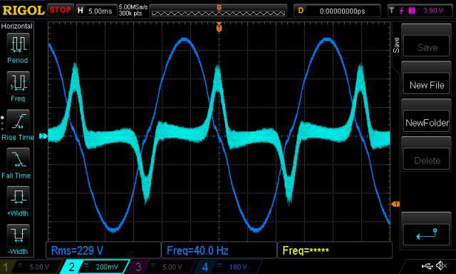 The earlier code (when changing from "stop" to "run") will terminate the soft stop ramp down and reset the code to initial conditions required for a soft start and then start ramping up. The ramp position is set to zero when initialised. This code execution will occur at the time the run/stop signal is checked and this check happens at 100Hz, every zero crossing. Think of it as a clock, ticking at 20kHz, making a PWM pulse. This is the only interrupt and so it is never interrupted by other code. It always will be executed, with very little time jitter (+/- a few ns) and make a pulse. In the spare time after the interrupt has completed which is about 80% of cpu time, the code can do what else is needed such as respond to a zero crossing. The zero crossing event triggers the PID closed loop code to run as well as the checking of the run/stop signal. wronger than a phone book full of wrong phone numbers |
||||
| wiseguy Guru Joined: 21/06/2018 Location: AustraliaPosts: 1210 |
Sanity check....I need to restate my initial observations. When I start the inverter after a completed soft stop it always grunts. When it is restarted during an interrupted soft stop, despite it resetting and running the code as from a cold stop, it never grunts. I perceive a difference that as yet I have not found (understood?) an explanation for. My experiment involved waiting until the sinewave was still just perceptible in the soft stop and would have full stopped within another 0.5 second or so if I had not set the switch back to run. My recent question was related to the interrupt process (caused by setting the switch back to run) which clobbers the ramp down process early. It occurs after the switch is set from stop to run & I wanted to ascertain if the switch was immediately sensed and acted on anywhere in a cycle, or if it was read at a specific time in the code (ie zero cross). From your post I believe it is at a zero cross and even though the power delivery throughput might be truncated, the actual sine is always near zero when it is clobbered before the restart ? These questions are to help me focus/understand what the software is actually up in this process as I believe there is something subtly different between; a soft start after a full soft stop a soft start issued/initiated during a soft stop ramp down, that if I understand you is not supposed to be any different to the normal soft start? But one grunts the other never grunts. I am not asking for a response or a cure in this post I am just clarifying (to myself?) where this search started and what I was searching for and why. I accept that maybe I cant see the woods for the trees - but I am not trying to be purposely difficult though. One of us seems to be missing something and I am getting more & more concerned that it is me (seriously). In this discussion I am beginning to relate to the rooster in this link Now I will go and try the new code and report back soon If at first you dont succeed, I suggest you avoid sky diving.... Cheers Mike |
||||
| wiseguy Guru Joined: 21/06/2018 Location: AustraliaPosts: 1210 |
Ok new code installed and the ramp up grunt is very much reduced along with the peak current (down from ~450mA to ~ 390mA), but there is another interesting side effect too, this code when settled - there is a gentle buzzing that climbs and falls in level a bit - it takes a while (30 to 60 seconds to fully settle) and the input current also climbs and falls slightly (talking less than 10mA in 371mA) in sync with the buzz. It all settles after ~ 1minute at ~ 17.1W & 371mA. There is then just a faint gentle hum just like the mains. With the original code, the grunt is as strong as ever, it does not wander but just slowly decreases and settles to ~ 374mA & 17.3W but there is always a gentle buzz on top of the hum that never goes away completely. I am not complaining or asking for any further changes here, I am simply reporting what I observed. I swapped the nanos back and forth 3 times to check that is was not only repeatable but also predictable. I used to work with another older engineer and he would sometimes utter the statement that something was of monumental inconsequence - this may well be one of those events...... I suspect that if I reprogrammed the two nanos with each others code maybe it might be slightly different again. Peter there is something I would really like to try if you would indulge me further if you have the time and patience. During ramp up when Vfb = setpoint then no bang bang & go straight to pid. The other less preferred trial is, ok retain bang bang, but only increment and decrement level changes in pairs, ie at 50 Hz so changes are balanced whilst bang bang is shuffling back and forth. ĀWhich ever is easiest. Edited 2022-07-05 18:17 by wiseguy If at first you dont succeed, I suggest you avoid sky diving.... Cheers Mike |
||||
| poida Guru Joined: 02/02/2017 Location: AustraliaPosts: 1432 |
ok, will see what I can do tomorrow. probably can do the immediate transition to PID once Vfb = setpoint The change in pairs will be simple too. I only run PID/bangbang at 50 Hz this would make a change so that subsequent cycles will be larger or smaller by the same amount. So that means no 100Hz update but now 50Hz update wronger than a phone book full of wrong phone numbers |
||||
| wiseguy Guru Joined: 21/06/2018 Location: AustraliaPosts: 1210 |
Thanks Peter that will be fine. My rethink on how best to avoid flux wander is to have balanced 360 degree cycles. I know there will need be a step changes during ramp up etc but after an increment step the increased amount of the next 180 degrees after the step change should be reflected in the next/following 180 degrees, so I am very happy with 50 Hz control & steps. I am aware that corrections to output loads etc may be slightly slower but I am happy to accept that. I have also decided that if this experiment does not work/improve the grunt I will just go with the slower ramp time and be happy with the quieter grunt. Two pictures of the new design with 16 HY5608s ready to detonate...... 8010 Control PCB with 8way connecting cable. 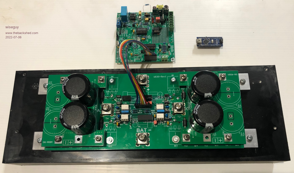 Vertical shot to see the multiple transistor sandwich. 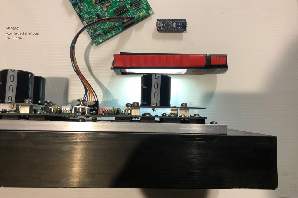 If at first you dont succeed, I suggest you avoid sky diving.... Cheers Mike |
||||
| rogerdw Guru Joined: 22/10/2019 Location: AustraliaPosts: 906 |
That's looking great Mike, love how compact it looks. And it should be good for 5kW with the right transformer? You must be close to sorting out the 'grunt' issue, it surely can't elude you much longer. I'm happy to visit and help get started with the winding if you do go down the track of winding a pair of cores. Cheers, Roger |
||||
| poida Guru Joined: 02/02/2017 Location: AustraliaPosts: 1432 |
here are the two changes. nano_1_v7_no_bessel_smooth_stop_PID_as_soon_as_Vfb.zip and nano_1_v7_no_bessel_smooth_stop_50Hz_control_loop.zip I based it on the 250 step ramp soft start code. Both will require the SCR over current signal to be pulled low to enable the inverter to run. (I think that is what you need.) if not, make the change by commenting one line and uncommenting the other in this part: // scr shutdown - without a dummy connection of D6 to ground, inverter wont run. if (((PINB & 0x01) == 0) || ((PIND & 0x40) == 0x40)) // for testing, do not check scr shutdown pin, just nano2 on/off //if (((PINB & 0x01) == 0) ) I forget which one you need. Anyway, to make it run Vfb control code at 50Hz only need one line to be changed: void loop() { float ch0; // sample channel.. // In the past, I low pass filtered this. not now, no need thanks to active LP filter on Vfb ac_output = (float)analogRead(ADC_OUT) / 1024.0; // scale 0 - 5V to 0.0 to 1.0 if(uf == 1 && (v1low == 1) ) // this will execute at 50Hz now { // it runs at near zero volt crossing of AC output and for the "Stop bang/bang control as soon as possible" version it's if (oen == 1) // slow stop? I think of it as de-gauss { if(ac_output < ac_setpoint) pwr += 1.0/250.0; // bang-bang control, should AC output reach setpoint prior to PID. else // During slow start need to ensure output is tracking setpoint { pwr -= 1.0/250.0; // should output get close enough to matter. sst = 251; } } else pwr -= 1.0 /250.0; // this will execute in slow stop } One thing that is a growing concern for me is the increasing evidence that the LC tank circuit that is the primary winding + choke + capacitor is ringing like a bell. I think it's looking for any reason to resonate to destruction. What is it's resonant frequency? I can't recall if you told us that here. The trigger for me was reading it needed 1 minute to settle down. OR it's a result of the PID control loop. (plus delay/freq. response of Vfb filter) wronger than a phone book full of wrong phone numbers |
||||
| wiseguy Guru Joined: 21/06/2018 Location: AustraliaPosts: 1210 |
Peter Thanks for the code mods to try out, you raised an interesting point re resonance. The choke and capacitor usually has a resonance > 500Hz. However the capacitor and transformer is the fundamental one usually discussed. When I had a single transformer its resonance for 50Hz and 75Hz was 3.5u and 2.1u respectively. Now that I have 2 transformers in parallel I had a 4u7 capacitor across the output and I cant recall ever rechecking the resonance. ĀMy earlier experiments had shown me that despite Warps warnings about resonance build up and becoming an issue I never had or experienced any ill effects resonating at 50 or 75Hz. ĀIn fact there was slightly less distortion at 50Hz. So I fired up the signal generator and checked the resonance of the 2 transformers in parallel setup I am using, it was now 150Hz which as a fluke also happens to be the third harmonic of 50 Hz. ĀI calculated the inductance to be 0.239H so I found another 12uF and connected that in parallel with the 4u7, I checked with the signal gen that resonance was now near 80Hz and then ran the inverter again. The secondary current due to the capacitance on the transformer revealed ~ 1.2A flowing, the idling current went from 17.2W to ~20.5W and ramp grunt etc was essentially unchanged - slightly worse if anything but the buzz at idle was now a bit louder. FYI, the secondary current with just the 4u7 was ~ 0.35A) Some more calcs show me that I would need 18.8uF to resonate at 75Hz or 42u for 50 Hz. ĀSurely there is something rotten here to need such large capacitance to resonate ? ĀI did not disconnect the inverter power board but all the FETs were off so I believe it is valid to leave it connected. It was a very low level from the signal generator I'm guessing less than a volt. The best result is still the 1000 step ramp up but I want to work out what to do with the transformer capacitor issue before experimenting further. ĀAny ideas or comments to help would be appreciated. Edited 2022-07-07 22:53 by wiseguy If at first you dont succeed, I suggest you avoid sky diving.... Cheers Mike |
||||
| wiseguy Guru Joined: 21/06/2018 Location: AustraliaPosts: 1210 |
Hi Roger as you will see from my last post there are still some gremlins to sort out. I intend to start stripping a couple of toroidal transformers soon in readiness for a single larger transformer solution. So starting that is still probably a few weeks away. Thanks for the help offer. Where did you buy your new winding wire from - I am assuming it was local in Adelaide somewhere ? If at first you dont succeed, I suggest you avoid sky diving.... Cheers Mike |
||||
| wiseguy Guru Joined: 21/06/2018 Location: AustraliaPosts: 1210 |
Ok Today I re-tested for resonance with my transformers and got quite different and more believable results. I did find a clip-lead that was open circuit and another with a dubious crimp connection. Usually I dismantle and solder clip leads as I have never trusted their wire crimp connections, don't know how this one missed out. ĀThat must explain the crap results. The strange thing is that after working out the L from the resonance formula and adding capacitors etc all the calculations and measurements looked correct? Just goes to show, crap in = crap out..... (a bit like 1 = 2 Ā-that sounds familiar hmmm) The much better figures I got today is for resonance at 76 hertz = 6.7uF still high but only 36% of yesterdays calcs so I will set it at that. An interesting discovery during the re-testing was that I got the same resonance with just one 240V winding as I did when both 240V windings were connected in parallel. ĀThis didn't make sense at first. Then I realised the 48V spwm windings were still connected in parallel. This effectively put the 2 x 240V windings in parallel - on the same core effectively if you think about it. If I had disconnected/separated the 48V spwm windings I would have got a much different result, but the connections were buried & not easy to access. It is like winding two bifilar windings on the same core and discovering that with one winding you get the same uH value as with the other or with 2 windings connected as one, then they just have half the R value with the same number of effective turns & inductance. ĀProbably useless information for most... Now to get back to testing Poidas new codes, but with resonance now in check ! Edited 2022-07-08 19:26 by wiseguy If at first you dont succeed, I suggest you avoid sky diving.... Cheers Mike |
||||
| rogerdw Guru Joined: 22/10/2019 Location: AustraliaPosts: 906 |
Yes, gremlins ... and I'm glad it's you and not me. I wouldn't stand a chance.  Many years ago I bought a lot of copper winding wire from OH O'Briens in Adelaide. When I looked to buy some for the warpverter the first place I found was Advanced Thermal Supplies. 30 Pope St Beverley SA 5009 Ph. 08 8244 4411 I don't know how much they sell or who else might be around but I was surprised when they told me they don't 'despool' the wire there .. they get someone else to do it for them ... so you have to specify the wire size and what weight you want ... then they send it off to be despooled. Now that I've written that all out ... I wonder if they even keep any wire there themselves and simply buy it in from elsewhere on receipt of any orders. Regardless, each time I ordered some it only took an extra day and they rang with an exact price so I could pay via EFT and then they sent it up by courier. At least for you, you could make a trip across town to pick it up . Good luck with the new code. Cheers, Roger |
||||
| wiseguy Guru Joined: 21/06/2018 Location: AustraliaPosts: 1210 |
Thanks for the info Roger, I have a source now ! Boy have I been having fun today, every time I went to confirm the resonant frequency I was getting different answers and I was getting quite frustrated. I was beginning to doubt my sanity again - some others may have already wondered..... The remanence in the transformer can apparently change the resonant frequency by nearly 100%.To confirm my findings I ran the nano code with a slow stop. Then I checked my resonant frequency and it was 76 Hz. Next I turned on a variable source with 1V @ 0.5A and placed it across the mains winding momentarily. Bingo! the resonance peak dropped and after a re-tune the peak was now at 132Hz. I then ran the nano code & soft stop and we're back to 76Hz AT LAST I finally nailed it !! ĀEven 50mA momentarily injected could cause a 20Hz shift in the peak I was using a signal generator, output 5Vp-p sine and a 15K resistor in series with the 240V winding and parallel capacitor, the CRO was across the winding. So when checking the resonant frequency, the core should be de-magnetised/de-gaussed or you can end with a misleading answer, this was totally unexpected ! ĀThe signal generator was also capable of removing the remanence by shorting the 15K resistor and driving at resonance and reduce the output slowly to zero. Unshort the resistor and resonance is back to its lowest value, for my set up 76 Hz. I also found that even disconnecting the signal generator whilst running & checking resonance and reconnecting it could temporarily detune the result also. The crux (flux?) of this finding is that the inductance is reduced if there is any remanence still in the core, this will result in an increased resonant frequency value. Last test, I shorted the transformer/choke connection points on the Power PCB (no power connected to inverter !!) whilst I still had the resonance set-up connected, this enabled the last test to be done, I tuned for the peak which was found for my setup at 760Hz. this is the mains capacitor & choke combination resonance. Edited 2022-07-09 02:25 by wiseguy If at first you dont succeed, I suggest you avoid sky diving.... Cheers Mike |
||||
Revlac Guru Joined: 31/12/2016 Location: AustraliaPosts: 1153 |
I can see how much fun you had, that's kind of fun you try not to have again  ....I think thats how it works. ....I think thats how it works.  The amount of capacitance required to get it to 75Hz is definitely unique to each built, can't even guess what it would be....I tried that.......failed. I didn't run into the problem of the resonance change, I did the testing a little different. The signal generator was set to 75Hz to begin with, connected to the secondary winding and running, then add capacitance until the the peak could be seen on the OSC, or go a little past it with another cap to be sure, then removed the capacitors make a note of what size I need. Start and stop with caps removed, I don't think I had the choke connected any time at all. Anyway glad you found what it needs. Cheers Aaron Off The Grid |
||||
| wiseguy Guru Joined: 21/06/2018 Location: AustraliaPosts: 1210 |
Aaron, first I installed a capacitor across the winding. The reason I looked for the resonance with a sweep was that it cuts out some guess work & tells me where the peak is now, if the frequency is greater than 75Hz I need to add more capacitance, if less I need a smaller cap. Alternatively you could use the resonant frequency formula and solve for L Āusing the existing caps value for C and the resonant peak for F. Then plug the calculated L back into the resonance formula using 75Hz for F and solve for the total value of C required - I proved that it does work. I have good news and I have bad news. The good news is I modified the code and it finally started quietly with minor grunt & overshoot and very brief hunting whilst it settled, using the 1000 step code. ĀI then tried to modify the 1000 step original code to see if I could get it to start and settle faster, still accepting the low level grunt. The bad news is a (good?) cure was found, but unfortunately the patient died in the process of trying for even more improvement Ā  I am embarrassed to actually say what I did, cause Poida will point out what I did was probably really stupid and couldn't have fixed it, so okay here goes, fess up - get the dunce hat ready..... I changed sst = 0 to sst = 100, I had been reasonably happy with the quieter grunt but I wanted to speed up the ramp. I reasoned that if the ramp was now 1000, I could save 100 steps of time at the beginning of the ramp as there was not a lot happening down there. ĀIn fiddling with the sst number some unusual things happened, one of these was a very loud bang, but we'll get back to that later. Poida rolling on the floor laughing about now  When I changed sst = 200 it appeared to change the timing between when D8 got the start signal and when D5 enabled the outputs ( it actually behaved as though D5 was already high before D8 told it to start). So ok I then tried sst = 100 & voila grunt was totally gone, a very stable start up and no dithering at the end of ramp, life was looking good - briefly. Then feeling gung-ho/smug I decided to try the other code; 2022-07-07_093602_nano_1_v7_no_bessel_smooth_stop_50Hz_control_loop Which only had 250 step start up so I went for a smaller sst value to see if it helped with the grunt on this codes faster ramp - what could go wrong.... I tried sst = 100 but the D5 issue was happening again so I reduced to sst = 80 and tried again, the result was a fairly large grunt - bang event. ĀThis time though I need to totally rebuild the power board, after the previous bang event & repair 6 odd months ago, whilst soft starting the inverter with a compressor on the output, I would not trust it for further rework. It served me well and I was using it as a test bed before I hooked up my latest power board to the nano, I really wanted to solve the grunt if possible and decided on sacrificing the original inverter for experiments. So Poida why does sst = 100 make my inverter start with no grunt and no slight overshoot or slight wiggles whilst settling, it just rose and sat solid with a gentle hum. I thought sst was a count up to 1000/1001 starting at zero normally - what did my sst = 100 actually tell it to do ? The failure mode was very similar to the first failure, one of the 4 high side FETs had become shorted and saved its 3 mates, but when the bottom FETs turned on the dead upper FET passed enough instantaneous current to despatch all 4 low side FET's Āto FET heaven (or is that FET hell) any way I'm in the process of fixing it up again for more torture. There is a bit of a coincidence going on, due to the inverse optocoupler I deduce that shoot through is not the problem and that trying to drive a saturated choke/transformer is the likely culprit. A FET on the high side died in both cases whilst ramping current to the choke/transformer whilst grunting. It is reasonable to guess it (they) exceeded their max current rating and one was faster to sign off and Ātake one for the team, before then taking out the whole other half of the team when they were next commanded Ā"on". Ā Last query Peter, the 250 step code I believe takes 5 seconds, I expected the 1000 step code (un modified by me) to take 20 seconds but it only took 10 - something that I didn't quite get. It's probably something to do with 50 versus 100 Hz steps...... After sleeping on it and then reviewing what I did against what I should have done. ĀI offer the following advice - as Poida said somewhere - they are your FETs ! Ā(respect them) So the moral of the story is after making software changes - especially if software is not your forte - Āit would be wise to analyse the outputs with a CRO first and maybe a small output test stage and use a current limited supply and small bulk capacitors, before taking out a heap of FETs and the ensuing grief of repairs. Edited 2022-07-10 15:49 by wiseguy If at first you dont succeed, I suggest you avoid sky diving.... Cheers Mike |
||||
| poida Guru Joined: 02/02/2017 Location: AustraliaPosts: 1432 |
aw Jeez Wiseguy. you broke it. last question: Last query Peter, the 250 step code I believe takes 5 seconds, I expected the 1000 step code (un modified by me) to take 20 seconds but it only took 10 - something that I didn't quite get. It's probably something to do with 50 versus 100 Hz steps...... You are correct. I made a 1000 step version and that uses 100Hz updates so it needs 10 seconds to get to PID change over. The 50 Hz update version used 250 steps and needs 5 seconds (250/50..) before PID takes over. To change the step number here is what you need to do: for instance, if it's 250 and you want 100 then find all the "250" in the below code and change to "100" find all the "251" and change it to "101" find all the "250.0" and change it to "100.0" .. void loop() { float ch0; // sample channel.. // In the past, I low pass filtered this. not now, no need thanks to active LP filter on Vfb ac_output = (float)analogRead(ADC_OUT) / 1024.0; // scale 0 - 5V to 0.0 to 1.0 if(uf == 1 ) // this will execute at 100Hz { // it runs at near zero volt crossing of AC output uf=0; ac_setpoint = 0.55; // for same Vfb as EG8010. change AC output voltage via Vfb voltage divider trimpot if (oen == 1) sst++; // slow start. If output is enabled, keep starting up. sst = output pwm% or approx. voltage. if (sst > 251)sst = 251; // stop increasing when sst has got to the end of slow start. when = 251, this enables PID. See below.. if (oen == 0) sst--; // if stopping, slow stop if (sst <= 0) // once fully stopped, no more changes to sst needed { sst = 0; cbi(PORTD,5); // pull IR2184 shutdown LOW to disable gate drive output } else sbi(PORTD,5); // pull it HIGH, to enable output if(sst > 0 && sst < 250) // slow start timer counts to 250 with gentle ramp up, then switches over to PID control. (gulp!) { // sst can increase or decrease, giving the slow start and slow stop. if (oen == 1) // slow stop? I think of it as de-gauss { if(ac_output < ac_setpoint) pwr += 1.0/250.0; // bang-bang control, should AC output reach setpoint prior to PID. else // During slow start need to ensure output is tracking setpoint pwr -= 1.0/250.0; // should output get close enough to matter. } else pwr -= 1.0 /250.0; // this will execute in slow stop } if (sst == 251) // once sst = 251, run PID. the above bang-bang control will NOT have executed, because sst = 251 { Setpoint = ac_setpoint; Input = ac_output; do_pid(); pwr = pwr + Output; } ... I could or maybe should have already provided a setting via the menu to set the number of steps of the soft start/stop AND a setting for the control loop update rate. I thought there would be no need for it. When I changed sst = 200 it appeared to change the timing between when D8 got the start signal and when D5 enabled the outputs ( it actually behaved as though D5 was already high before D8 told it to start). possibly you did not change all of the above and so the soft start did not progress to output nearly equal to setpoint which is when I only ever want to switch over to PID control. And maybe D5 was enabled/HIGH at a bad time such as a sudden increase in PWM duty. I need to be the fly on the wall when you are doing your voodoo on the bench. I promise not to heckle. Unmodified nano_1_v7_no_bessel is bullet proof. I run this on my home inverter and it has restarted nearly daily for 3 years now and it still runs great. I can't help recalling the air compressor tests I did with a 4 x 3 FET inverter running nano_1_v7.. and seeing it do 12kW. No point to be made, it just came to mind then. When you get it right, you can move mountains with this system. I did the most testing on a 4 x 1 FET power board. 1kW load testing and lots of looking at Gate drive details. This board had about 6 x 3900uF caps on it and a current limited PS. The caps always would blow a FET if I got it wrong. But so easy to diagnose and repair. did I answer what you needed? I'm tired. Had a huge day on the mountain bike, stopped riding due to no more strength in my fingers and I could not hang on. I ride until I can't, it's so much fun. wronger than a phone book full of wrong phone numbers |
||||
| wiseguy Guru Joined: 21/06/2018 Location: AustraliaPosts: 1210 |
Nope - not even close :( Ābut thanks for trying - I will try to ask more concisely I wanted soft start to count up to 1000/1001 not 100/101 I tried to get soft start to begin from count 100 up to 1000/1001 (saving 100 steps low down) So I changed SST value from SST = 0 to SST = 100 in the 5th line below headed by ** note: I thought most //comments of 250/251 should have been changed to 1000/1001 ?? I never touched anything else. The code below started the inverter perfectly no grunt whatsoever, best start ever repeatedly. But changing back to SST = 0 grunted again. Obviously it seems my setting to 100 changed something for the better - but what ? Also making SST = 200 appeared to make D5 high the second I set D8 to go - from the code I couldn't see why. void init_vars() Ā Ā Ā// called prior to setting oen = 1, as well as from setup() Ā{ ĀICR1 = PPWM; Ālv_stopped = 0; Ā **sst = 0; Ā Ā Ā// slow start counter 0 - 251 Āv1low = 1; Ā Ā// half wave output flag, 0 or 1 Āpcount = 0; Ā // counter for sine wave lookup table Āuf = 0; Ā Ā Ā // set to 1 to enable AC output voltage feedback code to execute Āpwr = 0.0; Ā Ā// PWM duty cycle analog, 0.0 to 1.0 Āvpwr= 0; Ā Ā Ā// integer equivalent of pwr, 0 to PPWM Ādbounce = 0; Ā// debounce counter for input switch Ākp = 0.1; Ā Ā // set up PID for AC output voltage control Āki = 0.0; Ākd = 0.01; ĀerrSum = 0.0; Ā Ā Ā Ā// initialise PID ĀlastErr = 0.0; Āint_f = 0; Ā Ā Ā Ā Ā //used in AC sync, one shot per 50Hz Āif (p_lock == 1) Ā Ā{ Ā Ā // nothing to do so far Ā Ā} Āelse Ā Ā{ Ā Āp_lock = 0; Ā Ā Ā Ā Ā// phase lock flag = 0 = NOT locked Ā Āpcount_acc = 0; Ā Ā Ā// fractional integer math. Each PWM, pcount_delta is added to pcount_acc and divided by 1024 Ā Āpcount_delta = 1024; // in effect we are getting an addition of 1. But pcount_delta can be modified, a little bigger or smaller.. Ā Āold_phase_error = 0; // used in PID, to obtain derivative Ā Ā} Ācbi(PORTD,4); Ā Ā} void do_pid() { Ā Ā double timeChange = 0.01; Ā Ā// always called at 100Hz, so dT will be 10msec.. Ā error = Setpoint - Input; Ā errSum += (error * timeChange); Ā dErr = (error - lastErr) / timeChange; Ā Output = kp * error + ki * errSum + kd * dErr; Ā lastErr = error; } void loop() { Āfloat ch0; Ā// sample channel.. Ā// In the past, I low pass filtered this. not now, no need thanks to active LP filter on Vfb Āac_output = (float)analogRead(ADC_OUT) / 1024.0; // scale 0 - 5V to 0.0 to 1.0 Āif(uf == 1 Ā) Ā Ā// this will execute at 100Hz Ā Ā Ā{ Ā Ā Ā Ā Ā Ā// it runs at near zero volt crossing of AC output Ā Ā Ā Ā Ā Āuf=0; Ā Ā Āac_setpoint = 0.55; Ā Ā Ā // for same Vfb as EG8010. change AC output voltage via Vfb voltage divider trimpot Ā Ā Āif (oen == 1) sst++; Ā Ā Ā// slow start. If output is enabled, keep starting up. sst = output pwm% or approx. voltage. Ā Ā Āif (sst > 1001) sst = 1001; Ā// stop increasing when sst has got to the end of slow start. when = 1001, this enables PID. See below.. Ā Ā Āif (oen == 0) sst--; Ā Ā Ā// if stopping, slow stop Ā Ā Āif (sst <= 0) Ā Ā Ā Ā Ā Ā // once fully stopped, no more changes to sst needed Ā Ā Ā Ā{ Ā Ā Ā Āsst = 0; Ā Ā Ā Ācbi(PORTD,5); Ā Ā // pull IR2184 shutdown LOW to disable gate drive output Ā Ā Ā Ā} Ā Ā Āelse Ā Ā Ā Āsbi(PORTD,5); Ā Ā // pull it HIGH, to enable output Ā Ā Āif(sst > 0 && sst < 1000) Ā Ā // slow start timer counts to 250 with gentle ramp up, then switches over to PID control. Ā Ā Ā Ā{ Ā Ā Ā Ā Ā Ā Ā Ā Ā Ā Ā Ā Ā// sst can increase or decrease, giving the slow start and slow stop. Ā Ā Ā Āif (oen == 1) Ā Ā Ā Ā Ā Ā Ā// slow stop? I think of it as de-gauss Ā Ā Ā Ā Ā{ Ā Ā Ā Ā Āif(ac_output < ac_setpoint) Ā Ā Ā Ā Ā Āpwr += 1.0/1000.0; Ā Ā // bang-bang control, should AC output reach setpoint prior to PID. Ā Ā Ā Ā Āelse Ā Ā Ā Ā Ā Ā Ā Ā Ā Ā// During slow start need to ensure output is tracking setpoint Ā Ā Ā Ā Ā Āpwr -= 1.0/1000.0; Ā Ā // should output get close enough to matter. Ā Ā Ā Ā Ā} Ā Ā Ā Āelse Ā Ā Ā Ā Āpwr -= 1.0 /1000.0; Ā Ā Ā// this will execute in slow stop Ā Ā Ā Ā} Ā Ā Ā Ā Ā Ā Āif (sst == 1001) Ā Ā Ā // once sst = 1001, run PID. the above bang-bang control will NOT have executed, because sst = 251 Ā Ā Ā Ā{ Ā Ā Ā Ā Ā Ā Ā Ā Ā Ā Ā Ā ĀSetpoint = ac_setpoint; Ā Ā Ā Ā Ā ĀInput = ac_output; Ā Ā Ā Ā Ādo_pid(); Ā Ā Ā Āpwr = pwr + Output; Ā Ā Ā Ā} Would be great to have you as a fly on the wall, we would probably lick this in 15 minutes if we were in the same room......and there was no wine bottle opened.... Edited 2022-07-10 22:39 by wiseguy If at first you dont succeed, I suggest you avoid sky diving.... Cheers Mike |
||||
| poida Guru Joined: 02/02/2017 Location: AustraliaPosts: 1432 |
So I changed SST value from SST = 0 to SST = 100 in the 5th line below headed by ** note: I thought most //comments of 250/251 should have been changed to 1000/1001 ?? that should be fine. sst is the SlowStartTimer counter in the code. You chose wisely to make the change in the init_vars() block since that block of code also zeros the power factor that modulates the SPWM train of pulses. So when you have changed sst = 100 during init_vars() you will now have a count UP from 100 to 1000 before PID will take over. And when you stop the inverter, it will count down from 1001 to ZERO then disable the gate drive output (D5) and sst will remain at zero and the power factor (a variable named "pwr") will remain at zero. Changing sst = 200 within init_vars() would be that same as far as I can tell. Only this time it runs up from 200 to 1001, then PID takes over. Notice that the increments added to "pwr" remain the same, being 1.0/1000.0 This means no matter what value to give sst to start with, we will still see the output PWM duty width AKA "pwr" increase at the same rate. Now this is where it might become interesting: Should you have a DC supply and toroid wound such that you need more than 0.8 of max PWM modulation then the step change from bang/bang to PID will be abrupt. The steady increment of "pwr" from 0.0 to your AC setpoint will not get there in time before sst = 1001 and PID takes over. Let's say your transformer is wound so that with a 55V DC supply you need "pwr" to be 0.9 to achieve the AC setpoint voltage. with sst = 100 "pwr" will get to very close to the needed value of 0.9 just before PID takes over. If you start with sst = 200 then at the end, "pwr" = 0.8 and we need it to be 0.9 for the required AC output so the PID code will start with a large error term and so calculate a large correction value and this is what causes large step changes in the primary winding current. I always want the bang/band control to deliver a close enough value of "pwr" for the transition to PID. Anyway, what is your DC supply voltage, design primary voltage (AC V RMS please) and AC setpoint voltage? It could be that "pwr" variable does indeed need to be close to 0.9 at steady state.. My inverters are designed for 55V DC supply, 27V AC RMS primary (that is 38V peak to peak) and so gives me a nominal value for "pwr" of 0.69 when at approx 230V AC output. Also making SST = 200 appeared to make D5 high the second I set D8 to go - from the code I couldn't see why. D5 is pulled high when sst > 0 when sst = 0, D5 is pulled low. You can see this in the loop() code block. The aim of this is to only have D5 high during soft start, PID control and soft stop. Once the stop is completed, D5 is pulled low I do not think there is any difference in D5 behavior with different initialisation values of sst. Obviously it seems my setting to 100 changed something for the better - but what ? No idea but maybe the bang/bang phase during soft start is the cause of the grunt sound. Maybe you have far less sound once PID is in control. Maybe the least time spent in the bang/bang (i.e. steady, always increasing of "pwr" and therefore PWM duty width) soft start phase the better. Starting sst = 100 and a steady state "pwr" of 0.9 for your system would mean the soft start would only increase pwr from 0.0 to 0.9, then hover around 0.9 for a very small amount of time the PID switches in to control. The PID control is initialised to zero values within init_vars() so it will not perform smoothly if given a large error value at the first time it runs. The output of the PID with a large error will be a large correction which will be applied immediately to the SPWM pulse train (i.e. pwr will have a large change in value between control loop runs, which is 10 ms) and I do not want that to happen. Edited 2022-07-10 23:28 by poida wronger than a phone book full of wrong phone numbers |
||||
| wiseguy Guru Joined: 21/06/2018 Location: AustraliaPosts: 1210 |
I have rebuilt a new power PCB but before I hooked it up to the Nano I wanted to run some testing as I was sure there were some issues with D5, the enable for the outputs. The transformer is ~31.2V at ~235V out. It was intended to still provide 235V at 44V which is the low voltage cut out. If I did it again I would probably go for ~33V and be happy with a bit of droop below 46V as it approaches 44V. The following CRO pictures tell an interesting story (apart from my lousy/noisy ground). The Purple trace is the D8 input that tells the Nano "please start" The Yellow trace is D5 & its supposed to go High at ramp up start after D8 has been told "go". The Blue trace is just the 5V coming to life after turn on, for relativity. This is the 1000 step code as received 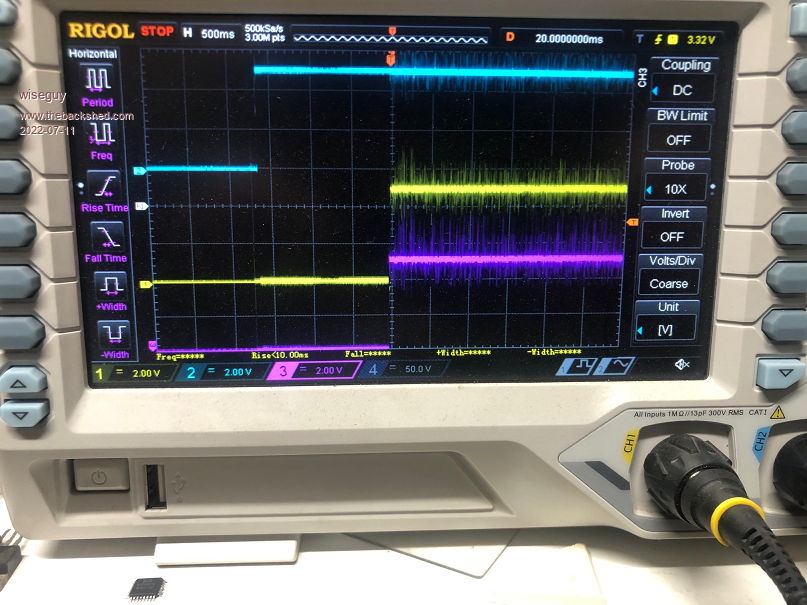 This is the 1000 step code with SST = 100 Note D5 went high for 1 second immediately the 5V rail went active & before D8 was told to "go" 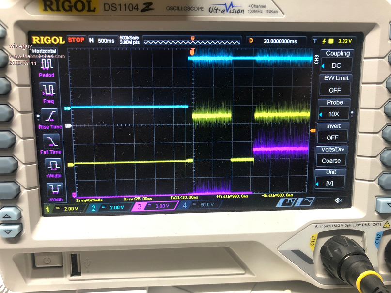 This is the 1000 step code with SST = 200 Note D5 went high after Power up and just stayed high 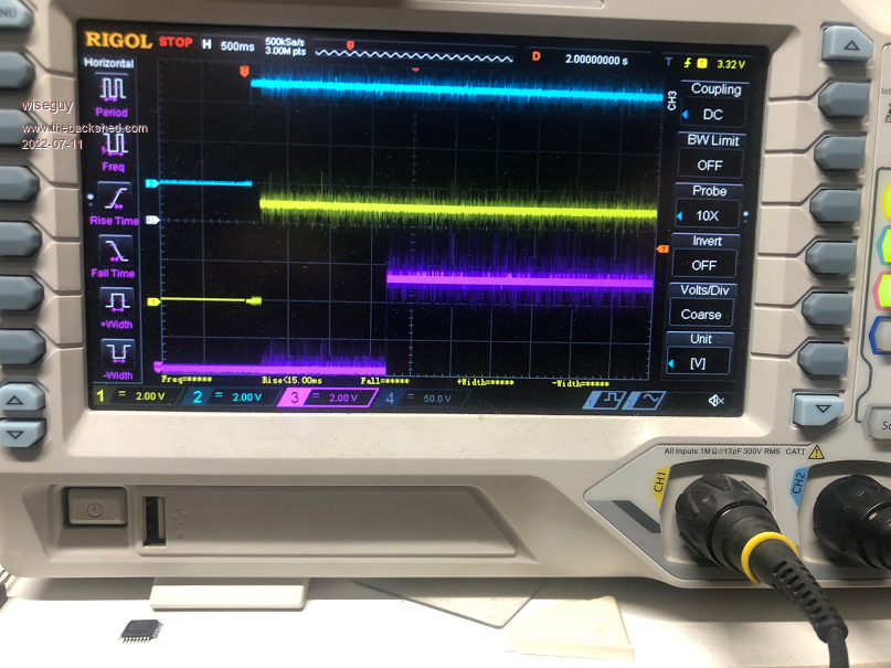 I did say yesterday that it behaved as though D5 was being enabled before the start command. Poida this is why we pay you the big bucks, to solve all the weird problems Ā Its probably caused by a missing comma or = sign or something simple but the results are a bit bizzare. Thanks for your comments on what I did and agreeing it should have had the effect I wanted - it looked reasonable to me but I am software challenged and software is easily broken..... The really sad part is that the middle picture with the premature enablation (is that a word ?) is the one that doesn't grunt and starts real nice Ā  Edited 2022-07-12 00:31 by wiseguy If at first you dont succeed, I suggest you avoid sky diving.... Cheers Mike |
||||
| The Back Shed's forum code is written, and hosted, in Australia. | © JAQ Software 2025 |
