
|
|
Forum Index : Electronics : Stock Std Warpinverter
| Author | Message | ||||
mackoffgrid Guru Joined: 13/03/2017 Location: AustraliaPosts: 460 |
Mark, that metal locker format is pretty much how I'm going with my next 100v inverter.  cheers Andrew |
||||
renewableMark Guru Joined: 09/12/2017 Location: AustraliaPosts: 1678 |
I already have a few spare lockers, but they are fairly narrow. That will not work fitting parts to the door, but thought some drawer slides like this might work. The torroids will just go in the bottom and not need to be moved, but assembling the fet boards etc might be fiddly without good access. Cheers Caveman Mark Off grid eastern Melb |
||||
| Warpspeed Guru Joined: 09/08/2007 Location: AustraliaPosts: 4406 |
You beat me to it Mark, I was going to suggest some nice heavy ball bearing slides. That would give excellent access to three sides of the inverter when it is slid out forwards. But beware of the whole thing tipping over, although lockers are deep and narrow, they are also fairly tall. I have 30 x 50Ah Winston cells that fit perfectly into a filing cabinet drawer stacked 6x5. Planned to use a second drawer and 30 more cells to double the battery capacity at some future time. I quickly realized how dangerous that could be. Overcame the problem by making the top layer of batteries fixed and accessed through a removable top. Only the lower battery layer is fitted on the original slides, and some tests proved this to be quite stable when pulled fully forward with 80Kg of batteries. I had made provision for bolting one or more barbell weights under the transformer plate, right at the back, but that turned out not to be necessary. There should be plenty of ways to make locker sheet metal work. The heavy steel base plate could even be made larger than the locker footprint for increased stability. Klaus says his inverter weighs in at a hefty 50Kg, so it all needs to be thought right through. One advantage of using filing cabinets or lockers is that if you stuff it up, its fairly simple to grab another, and just start again. Its always easy to look back on a project and think how it could have been done a much better way. So start with your roughest most battered locker, and experiment. Then save the really nice one for attempt number two. Cheers, �Tony. |
||||
| renewableMark Guru Joined: 09/12/2017 Location: AustraliaPosts: 1678 |
I'm going to use the small driver boards to directly run 2 fets from each for testing the system. After that I was wondering if those same driver boards could run the Mack power boards. Would this work? 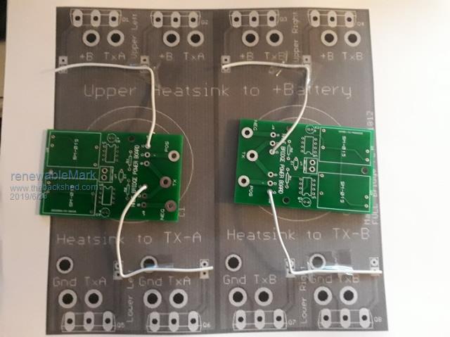 Cheers Caveman Mark Off grid eastern Melb |
||||
| mackoffgrid Guru Joined: 13/03/2017 Location: AustraliaPosts: 460 |
Mark, one gate resistor for 2 Fets is not ideal. But It will work. You also need to wire the gnd from the driver boards to the round pad. You could stick a resistor in each square pad on the Fet board and run a wire to each of those. Or mount a second resistor on the driver board and wire from each. I do have a spare driver PCB that you could mount your driver boards to. That would give you plug in header function, or if you want more than one, use vero board and make a compatible plug in board or my gerbers and cad files are on my github. Cheers Andrew |
||||
| renewableMark Guru Joined: 09/12/2017 Location: AustraliaPosts: 1678 |
Thanks Andrew, reckon I'll end up with your driver board then. Just thought I might be able to re use stuff already on hand. Those boards are cheap as hell, no biggie. I'll need to get my head around your control board now. Cheers Caveman Mark Off grid eastern Melb |
||||
| mackoffgrid Guru Joined: 13/03/2017 Location: AustraliaPosts: 460 |
Those boards are dirt cheap, especially if you co-load a couple to amortise the freight. What Power supplies do you intend to use? I've the component library for the Tony uses. I could look at making a driver board version to suit and cut the extraneous crap. You are not likely to be the last person to want it. I will likely to be the last person to build a 26volt warpverter though  . .You can use any of the controller boards, Tony's, the stm32_Warpverter or my eprom version. I think I can make it easier for people to get into the stm32_Waprverter (software that is), but more on that later. cheers Andrew |
||||
| renewableMark Guru Joined: 09/12/2017 Location: AustraliaPosts: 1678 |
Thanks mate, I have the small 12v isolated supplies like Warp uses. I have all the bits to make the 8 little Warp boards, so I'll get that going first. Just like to plan ahead for the next step. I have one of the Warp control boards, that will be fine. I have always worried about low voltage shutdown, but shouldn't really as the system has never gone anywhere near that level. A simpler driver board sounds like a great idea.  Your power boards can stack nicely to make a thin vertical unit, that will suit well. Cheers Caveman Mark Off grid eastern Melb |
||||
| Warpspeed Guru Joined: 09/08/2007 Location: AustraliaPosts: 4406 |
Mark, easy way is to get started with the control board you already have, and as you suggest, use four of the small half bridge driver boards you already have with individual HY4008s for the two smallest inverters. Then you can use Andrews boards for the two larger inverters. When its all finally up and running, finish it off with Andrew's Nano board. It will plug straight in. I am running Andrews Nano board in my own inverter right now. Both control boards work interchangeably, but the Nano board has the potential to add a lot of extra future functionality as the software grows and evolves over time. Cheers, �Tony. |
||||
| renewableMark Guru Joined: 09/12/2017 Location: AustraliaPosts: 1678 |
Yeah, caveman calculations. (overestimated outputs slightly for simplicity) No1 6kw No2 2kw No3 666w ooooohhhh nasty number  No4 222w So even flat knacker No3 will only pull 666w, with an extra 10% loss it's still only 15.26A @48v (but it will be more than 48v normally) Therefore even though the little boards don't appear to have a lot of grunt they should actually be just fine for No3 & certainly 4. In reality they may never see those numbers, other than short bursts for compressors etc. Cheers Caveman Mark Off grid eastern Melb |
||||
| Warpspeed Guru Joined: 09/08/2007 Location: AustraliaPosts: 4406 |
Yup. Number four contributes almost nothing power wise, but the effect it has on smoothing the final sine wave is just astonishing. Cheers, �Tony. |
||||
| renewableMark Guru Joined: 09/12/2017 Location: AustraliaPosts: 1678 |
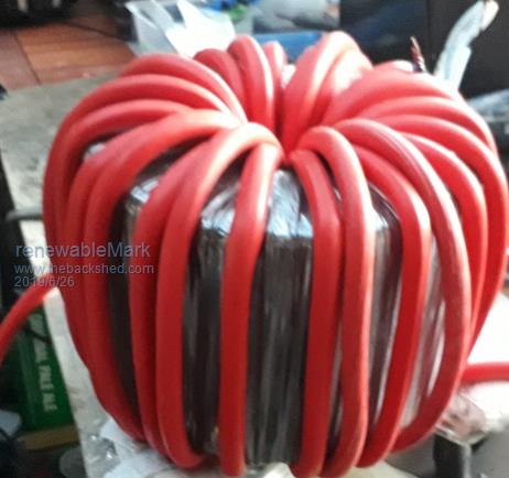 Got the 6kw torroid primary on, so all the torroids are all done now. Forgot to say, I got 15M and was left with 1M tails on each end... nice guess, actually I did calculate that  BS many will say but yeah for once I did. BS many will say but yeah for once I did. The No 2 torroid used 21M of primary, it comes std in a 30M roll, so will have some left for various crap. Just thought I'd put those numbers down in case anyone else does the same build. Cheers and more beers. Cheers Caveman Mark Off grid eastern Melb |
||||
| mackoffgrid Guru Joined: 13/03/2017 Location: AustraliaPosts: 460 |
Mark, guys, Would you happen to know the wire/w diameter on the inner winding of the AeroSharp 1500 transformer? Do you happen to have the core size? 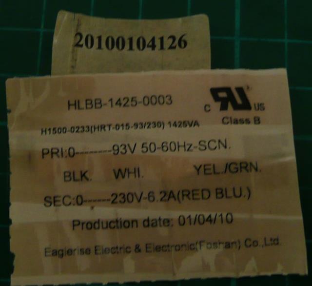 The outer winding, 230V, is 2 x 1.8mm dia Cheers Andrew |
||||
| renewableMark Guru Joined: 09/12/2017 Location: AustraliaPosts: 1678 |
The one I stripped had all the wire tossed, so can't tell for sure, but it looked all the same size to me. I thought they used 1.6mm diameter. 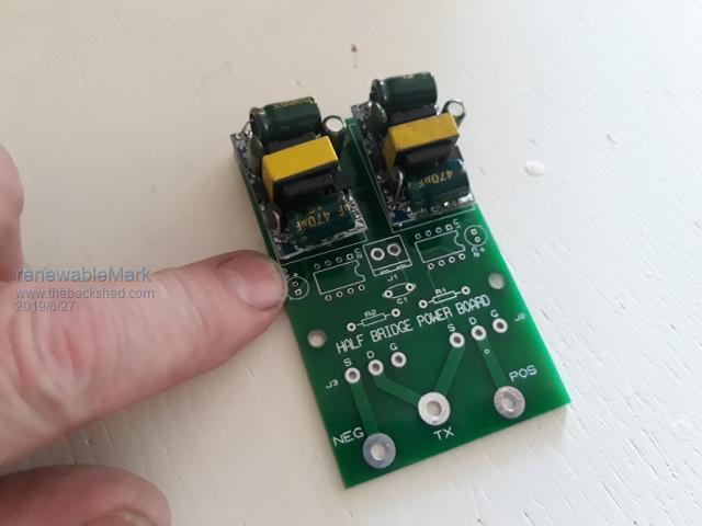 Tony, with the driver boards the DC output goes toward the centre of the board yeah? Cheers Caveman Mark Off grid eastern Melb |
||||
| BenandAmber Guru Joined: 16/02/2019 Location: United StatesPosts: 961 |
I really like this post I think it will help me in the future I also like mackoffgrids mosfet board It reminds me a little bit of one of the inverters you made warp speed I think it would be awesome with a nano single Transformer inverter Me and the wife went to the Smoky Mountains and was in need of a small 12 volt inverter Would really like to build one off of Macks mosfet board Does anybody else thank Mack's mosfet board would make a awesome little single Transformer inverter be warned i am good parrot but Dumber than a box of rocks |
||||
| renewableMark Guru Joined: 09/12/2017 Location: AustraliaPosts: 1678 |
1500w core id 94mm id to od thickness 46mm height 47mm Cheers Caveman Mark Off grid eastern Melb |
||||
| Warpspeed Guru Joined: 09/08/2007 Location: AustraliaPosts: 4406 |
Yes that is right, dc output to the middle. Input line/neutral to the edge of the board. Cheers, �Tony. |
||||
| renewableMark Guru Joined: 09/12/2017 Location: AustraliaPosts: 1678 |
Thanks mate, I'll fit all the little bits first on the next ones, just wanted to get a feel for how I'll mount them. The two inner connections I bent some header pins, the outer ones are a bit far apart from the pcb layout so they got insulated wires, all easy 2 min job. Cheers Caveman Mark Off grid eastern Melb |
||||
| mackoffgrid Guru Joined: 13/03/2017 Location: AustraliaPosts: 460 |
thanks Mark |
||||
| renewableMark Guru Joined: 09/12/2017 Location: AustraliaPosts: 1678 |
2kw Aerosharp. 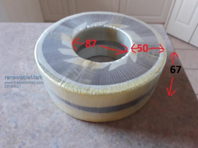 Cheers Caveman Mark Off grid eastern Melb |
||||
