
|
|
Forum Index : Electronics : Stock Std Warpinverter
| Author | Message | ||||
renewableMark Guru Joined: 09/12/2017 Location: AustraliaPosts: 1678 |
1500w Aerosharp 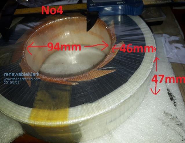 Cheers Caveman Mark Off grid eastern Melb |
||||
mackoffgrid Guru Joined: 13/03/2017 Location: AustraliaPosts: 460 |
Thanks. I try not to strip all the wire off my cores, where possible I re-use existing windings. So my core dimensions can be a bit of a guess sometimes. All your figures are useful to me including the num Turns you've provided. (I presume Tony worked those out?) Cheers Andrew |
||||
| renewableMark Guru Joined: 09/12/2017 Location: AustraliaPosts: 1678 |
Yes, Tony worked all those out based on my cores. Cheers Caveman Mark Off grid eastern Melb |
||||
| Warpspeed Guru Joined: 09/08/2007 Location: AustraliaPosts: 4406 |
Anyone that requires assistance, or some figures checking, please do not hesitate to ask. Cheers, ĀTony. |
||||
| renewableMark Guru Joined: 09/12/2017 Location: AustraliaPosts: 1678 |
Tony, on your control board R6 and R5 are dependant on dc input, so what shall I put there? J1 I assume that gets fed with my batt voltage (48) And the SM05 has the DC output on the right toward U8? Cheers Caveman Mark Off grid eastern Melb |
||||
| Warpspeed Guru Joined: 09/08/2007 Location: AustraliaPosts: 4406 |
Mark, R5 remains 3K3 R6 needs to be 82K for a 48v inverter. Tweaking potentiometer RV1 adjusts the inverter output voltage up and down. Initially set it to the middle, fire up the inverter, then fine adjust for exactly 230v output, or whatever. Yes, J1 is the direct raw 48v dc input to the inverter. Its marked +/- Yup, input of the SM-05 next to Ji. +5v dc output on the right next to U8 Cheers, ĀTony. |
||||
| renewableMark Guru Joined: 09/12/2017 Location: AustraliaPosts: 1678 |
Thanks Tony.....82k,....... back to jaycar. Cheers Caveman Mark Off grid eastern Melb |
||||
| Warpspeed Guru Joined: 09/08/2007 Location: AustraliaPosts: 4406 |
See how that goes Mark. That potentiometer is a very fine adjustment of inverter output voltage with not much range. Lots of turns and the output voltage moves very slowly. It may end up flat out clockwise with the inverter maximum output voltage still a bit less than you would really like to see, or it may be o/k. If you need more adjustment range, replace the 500 ohm pot with 1K pot and that should end up with both the pot adjustment closer to the middle, and with more overall adjustment range available in both directions. That will work with the 82K and 3K3 that you already have. Cheers, ĀTony. |
||||
| renewableMark Guru Joined: 09/12/2017 Location: AustraliaPosts: 1678 |
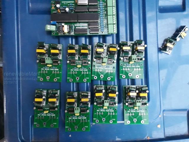 Almost finished the driver boards. Tony, if I fire the control board up connected to the driver boards I should see square wave signals from the gate pin on the driver board right? Cheers Caveman Mark Off grid eastern Melb |
||||
| Warpspeed Guru Joined: 09/08/2007 Location: AustraliaPosts: 4406 |
Should all look like this. The wires all fan out logically. 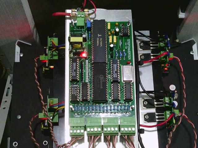 I don't have pictures of the individual gate drive waveforms here to show you, but you should definitely be able to see the drive to each mosfet gate with respect to its corresponding source. Only try to do that without any mosfets fitted !! If you ground the source of the upper mosfet with a mosfet fitted, it will go bang. Cheers, ĀTony. |
||||
| renewableMark Guru Joined: 09/12/2017 Location: AustraliaPosts: 1678 |
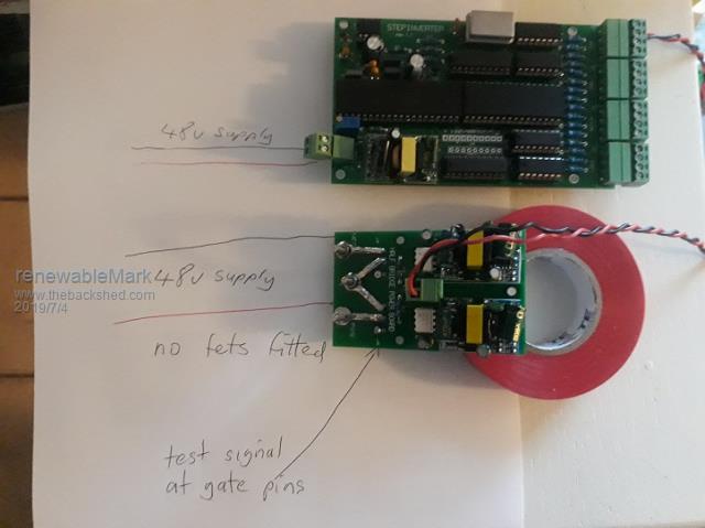 So wire it like this and it should show signals at the gate/s? Cheers Caveman Mark Off grid eastern Melb |
||||
| Warpspeed Guru Joined: 09/08/2007 Location: AustraliaPosts: 4406 |
Yes Mark, exactly like that. Between gate and source pins of each mosfet you should be able to see the gate drive waveforms. There will be a red LED that indicates that the small supplies are up and running. Then fit the two mosfets, and you should be able to see something that looks pretty much the same, but switches 0v to 48v on the TX pin. Cheers, ĀTony. |
||||
| renewableMark Guru Joined: 09/12/2017 Location: AustraliaPosts: 1678 |
Tiny torroid, left gate. 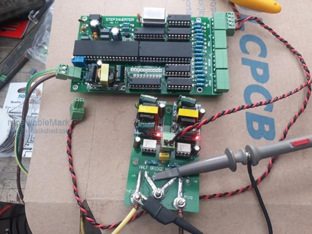 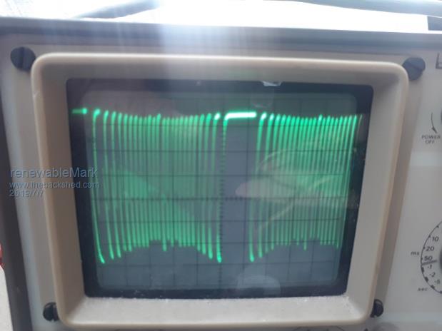 Tiny torroid right gate. 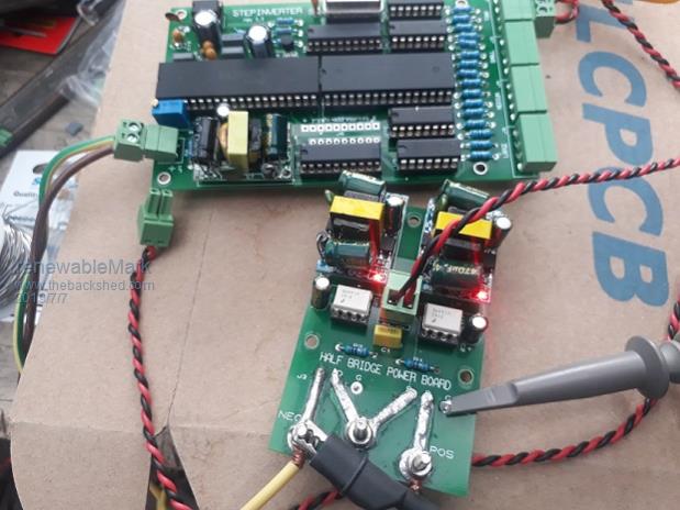 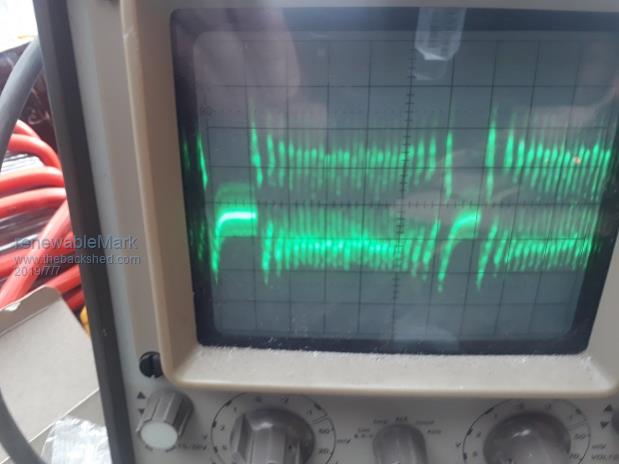 Right side looks a bit messy, can't seem to adjust the scope to get it looking clear. Small torroid left gate. 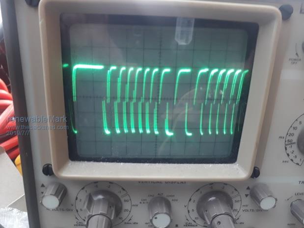 Small torroid right gate 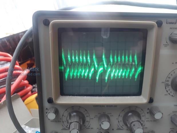 Cheers Caveman Mark Off grid eastern Melb |
||||
| Warpspeed Guru Joined: 09/08/2007 Location: AustraliaPosts: 4406 |
First two pictures look good. There is a problem with the next two pictures "right gate". You need to measure between gate and source of the right hand mosfet which you are not doing. Move the probe ground to the central TX connection, which is the source of the upper mosfet. Check your probe compensation, there will be a screwdriver adjustment either on the probe, or sometimes where the probe plugs into the CRO. https://www.youtube.com/watch?v=jzdqugRHoGo Cheers, ĀTony. |
||||
| renewableMark Guru Joined: 09/12/2017 Location: AustraliaPosts: 1678 |
Silly me, forgot to move the ground clip across.  Plugged it all back in and the trace flickered and stopped, then started making a funny crackle sound. Un plugged it opened it up and plugged it back in, a resistor was sparking. BWD 826 50mhz, can't find a manual for it or parts list. 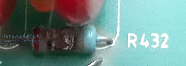 Cheers Caveman Mark Off grid eastern Melb |
||||
| Warpspeed Guru Joined: 09/08/2007 Location: AustraliaPosts: 4406 |
Oh, that is very bad Mark. BWD went out of business in the mid 90's and no longer exists. Did an internet search for the 826 and came up empty. I have a BWD 530A here and it took literally bloody years to finally track down the circuit diagrams for it. Anyhow there is a guy at KevinChant.com that has the circuits for an an 820 and 821 that may be similar enough to be useful. https://www.kevinchant.com/bwd.html Look for test instruments in the left hand column, then hit BWD. If you are really screwed, you can borrow my 530A and leave your 820 with me. No promises, but as a very last resort there might be a very faint chance I may be able to fix it. Cheers, ĀTony. |
||||
| Warpspeed Guru Joined: 09/08/2007 Location: AustraliaPosts: 4406 |
Found R432, its in the very high voltage section that supplies the CRT. There is an excellent chance that this identical circuit board is used in all of the 800 series of oscilloscopes. Its 2M2 and would explain why it sparkled and arced over and the display flashed. Cheers, ĀTony. |
||||
| renewableMark Guru Joined: 09/12/2017 Location: AustraliaPosts: 1678 |
Thanks Tony, it looks more like the 835, but the diagrams are totally different. Looks like it might be the part R604 150k 1W. Might give that a crack, if that fails it will be a door stop. Not worth doing my head in over a cheapie. Cheers Caveman Mark Off grid eastern Melb |
||||
| Warpspeed Guru Joined: 09/08/2007 Location: AustraliaPosts: 4406 |
Its worth a try, but I agree this old stuff is often not worth fixing. I keep mine, only because I may need an oscilloscope to fix an oscilloscope. Cheers, ĀTony. |
||||
| renewableMark Guru Joined: 09/12/2017 Location: AustraliaPosts: 1678 |
I think you are right, the 824 looks more like it. R432 looks correct as it's across two caps. I'll give that it's last chance. Cheers Caveman Mark Off grid eastern Melb |
||||
